
Installation
Abstract
When a gas turbine engine is installed in an aircraft it usually requires a number of accessories fitting to it and connections made to various aircraft systems. The engine, jet pipe, and accessories, and in some installations a thrust reverser, must be suitably cowled and an air intake must be provided for the compressor, the complete installation forming the aircraft power plant. The power plant location and aircraft configuration are of an integrated design and this depends upon the duties that the aircraft has to perform.
Keywords
Air intakes; power plant location; cowlings; gas turbine installation; mountings; accessories
“Throw your dreams into space like a kite, and you do not know what it will bring back, a new life, a new friend, a new love, a new country.”
—Anais Nin
Installation of Aircraft Engines1
When a gas turbine engine is installed in an aircraft it usually requires a number of accessories fitting to it and connections made to various aircraft systems. The engine, jet pipe, and accessories, and in some installations a thrust reverser, must be suitably cowled and an air intake must be provided for the compressor, the complete installation forming the aircraft power plant.
Power Plant Location
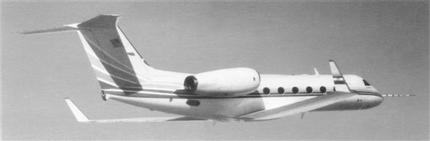
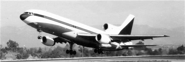
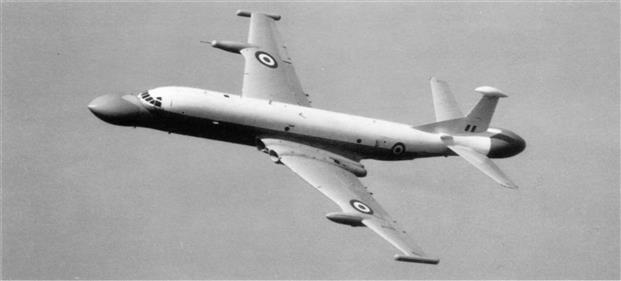
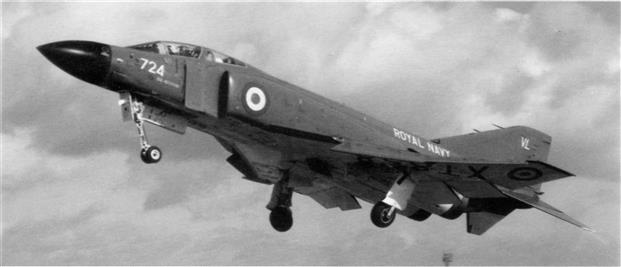
The power plant location and aircraft configuration are of an integrated design and this depends upon the duties that the aircraft has to perform. Turbo-jet engine power plants may be in the form of pod installations that are attached to the wings by pylons (Figure 13–1), or attached to the sides of the rear fuselage by short stub wings (Figure 13–2), or they may be buried in the fuselage or wings. Some aircraft have a combination of rear fuselage and tail-mounted power plants, others, as shown in Figure 13–3, have wing-mounted pod installations with a third engine buried in the tail structure. Turbo-propeller engines, however, are normally limited to installation in the wings or nose of an aircraft.
The position of the power plant must not affect the efficiency of the air intake, and the exhaust gases must be discharged clear of the aircraft and its control surfaces. Any installation must also be such that it produces the minimum drag effect.
Power plant installations are numbered from left to right when viewed from the rear of the aircraft.
Supersonic aircraft usually have the power plants buried in the aircraft for aerodynamic reasons. Vertical lift aircraft can use either the buried installation or the podded power plant, or in some instances both types may be combined in one aircraft.
Air Intakes
The main requirement of an air intake is that, under all operating conditions, delivery of the air to the engine is achieved with the minimum loss of energy occurring through the duct. To enable the compressor to operate satisfactorily, the air must reach the compressor at a uniform pressure distributed evenly across the whole inlet area.
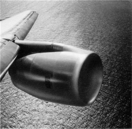
The ideal air intake for a turbo-jet engine fitted to an aircraft flying at subsonic or low supersonic speeds is a short, pitot-type circular intake (Figure 13–4). This type of intake makes the fullest use of the ram effect on the air due to forward speed, and suffers the minimum loss of ram pressure with changes of aircraft attitude. However, as sonic speed is approached, the efficiency of this type of air intake begins to fall because of the formation of a shockwave at the intake lip.
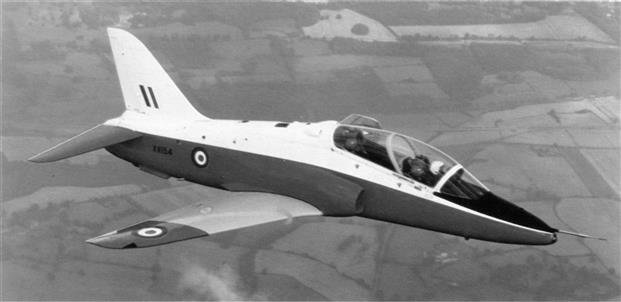
The pitot-type intake can be used for engines that are mounted in pods or in the wings, although the latter sometimes require a departure from the circular cross-section because of the wing thickness (Figure 13–5).
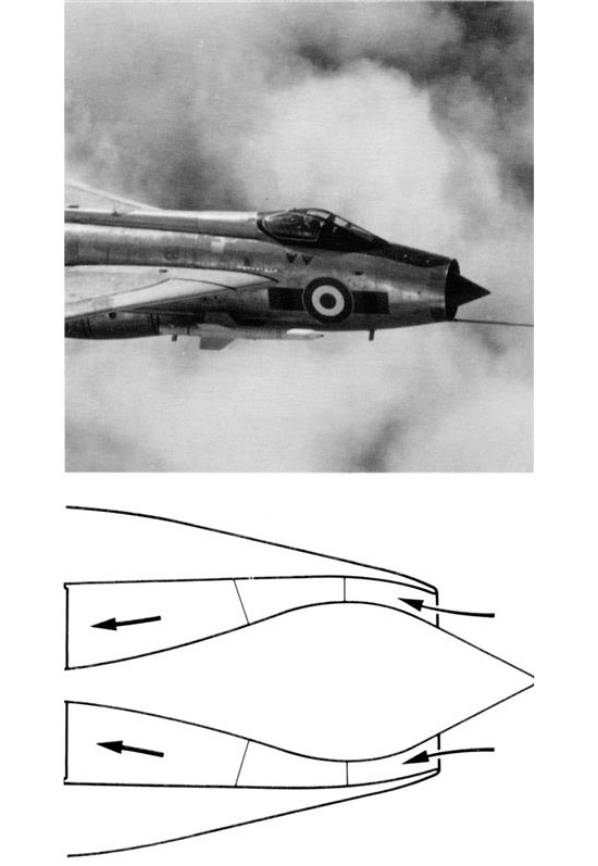
Single engined aircraft sometimes use a pitot-type intake; however, because this generally involves the use of a long duct ahead of the compressor, a divided type of intake on each side of the fuselage is often used (Figure 13–6).
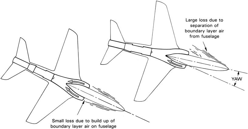
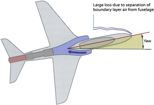
The disadvantage of the divided type of air intake is that when the aircraft yaws, a loss of ram pressure occurs on one side of the intake, as shown in Figure 13–7, causing an uneven distribution of airflow into the compressor.
At higher supersonic speeds, the pitot type of air intake is unsuitable due to the severity of the shockwave that forms and progressively reduces the intake efficiency as speed increases. A more suitable type of intake for these higher speeds is known as the external/internal compression intake (Figure 13–8). This type of intake produces a series of mild shockwaves without excessively reducing the intake efficiency.
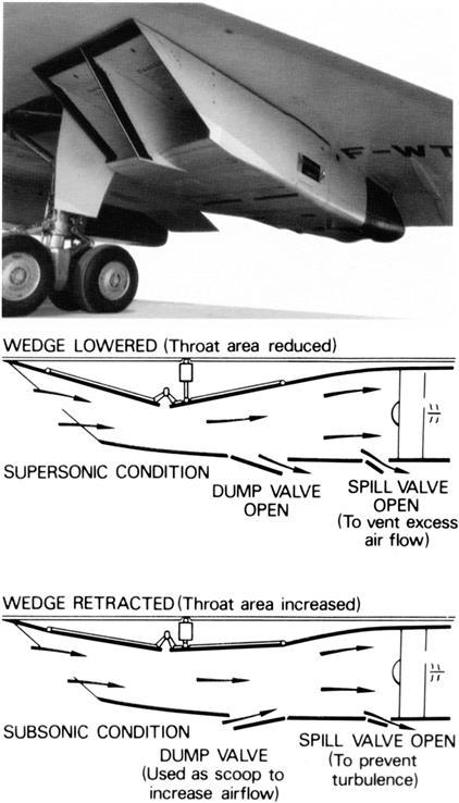
As aircraft speed increases still further, so also does the intake compression ratio and, at high Mach numbers, it is necessary to have an air intake that has a variable throat area and spill valves to accommodate and control the changing volumes of air (Figure 13–9). The airflow velocities encountered in the higher speed range of the aircraft are much higher than the engine can efficiently use; therefore, the air velocity must be decreased between the intake and the engine air inlet. The angle of the variable throat area intake automatically varies with aircraft speed and positions the shockwave to decrease the air velocity at the engine inlet and maintain maximum pressure recovery within the inlet duct. However, continued development enables this to be achieved by careful design of the intake and ducting. This, coupled with auxiliary air doors to permit extra air to be taken in under certain engine operating conditions, allows the airflow to be controlled without the use of variable geometry intakes. The fuselage intakes shown in Figure 13–10 are of the variable throat area type.
Engine and Jet Pipe Mountings
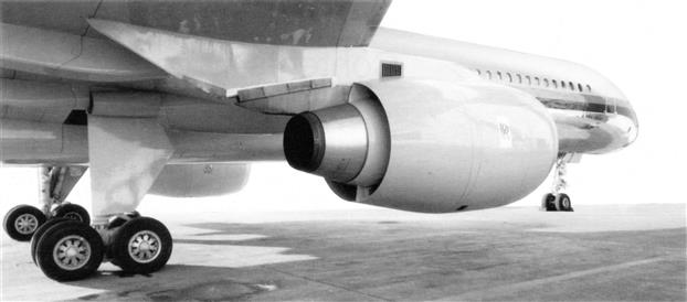
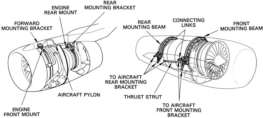
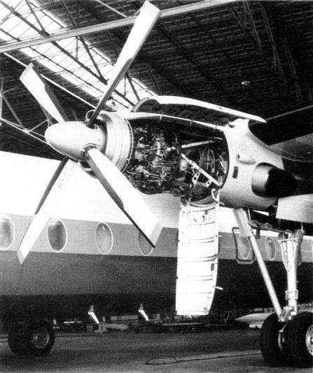
The engine is mounted in the aircraft in a manner that allows the thrust forces developed by the engine to be transmitted to the aircraft main structure, in addition to supporting the engine weight and carrying any flight loads. Because of the wide variations in the temperature of the engine casings, the engine is mounted so that the casings can expand freely in both a longitudinal and a radial direction. Types of engine mountings, however, vary to suit the particular installation requirement. Turbo-jet engines are usually either side mounted or underslung as illustrated in Figure 13–11. Turbo-propeller engines are mounted forward on a tubular framework as illustrated in Figure 13–12.
The jet pipe is normally attached to the rear of the engine and supported by the engine mountings. In some installations, particularly where long jet pipes are employed, an additional mounting is provided, usually in the form of small rollers attached to each side of the jet pipe. The rollers locate in airframe-mounted channels and support the weight of the jet pipe, while still allowing it to freely expand in a longitudinal direction.
Accessories
An aircraft power plant installation generally includes a number of accessories that are electrically operated, mechanically driven, or driven by high-pressure air.
Electrically operated accessories such as engine control actuators, amplifiers, air control valves, and solenoids, are supplied with power from the aircraft electrical system or an engine-driven dedicated electrical generator.
Mechanically driven units, such as generators, constant speed drive units, hydraulic pumps, low- and high-pressure fuel pumps, and engine speed signaling, measuring, or governing units are driven from the engine through internal and external gearboxes.
Air-driven accessories, such as the air starter and possibly the thrust reverser, afterburner, and water injection pumps, are driven by air tapped from the engine compressor. Air conditioning and cabin pressurization units may have a separate air-driven compressor or use air direct from the engine compressor. The amount of air that is taken for all accessories and services must always be a very small percentage of the total airflow, as it represents a thrust or power loss and an increase in specific fuel consumption.
Cowlings
Access to an engine mounted in the wing or fuselage is by hinged doors; on pod and turbo-propeller installations the main cowlings are hinged. Access for minor servicing is by small detachable or hinged panels. All fasteners are of the quick-release type.
A turbo-propeller engine, or a turbo-jet engine mounted in a pod, is usually far more accessible than a buried engine because of the larger area of hinged cowling that can be provided. The accessibility of a podded turbo-fan engine is shown in Figure 13–13 and that of a turbo-propeller engine is shown in Figure 13–12.
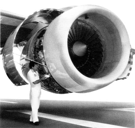
The fan cowl doors provide a continuous external aerodynamic surface for the nacelle while allowing easy access to all the engine fan case counted accessories. This access is achieved by having the fan cowl doors hinged to the aircraft pylon.
The top half of each cowl door is fire proof as the volume underneath them is a designated fire zone containing the fuel pumps and fuel lines. The airflow under the fan cowl doors must not be obstructed, so that the engine accessories are cooled and ventilated.
Fan cowl doors are typically made from composite materials with a number of access panels for maintenance. Some large fan cowl doors might have powered opening devices; all have “hold open” rods that have to ensure safe opening on the ground in winds of up to 110 kmh (60 knots).
Configuration is a short, near-circular, pitot-type intake. This design is highly efficient for subsonic operation, as low levels of pressure loss are achieved under all operating conditions. Civil pitot intakes are suitable for wing and rear fuselage mounted nacelles. For tri-jet configurations, s-duct intakes are a design option when the engine is buried in the rear fuselage.
Civil Nacelles
A nacelle is a streamlined enclosure that fits around a dressed engine and interfaces with the aircraft structure.
The primary objectives of a nacelle are to
• provide low drag, achieved through aerodynamic design of the nacelle itself and its interaction with the fuselage and smooth surfaces
• ensure good engine performance throughout the aircraft flight and ground envelopes
• reduce engine noise with acoustic treatment of nacelle structure
The nacelle must also be manufactured cost effectively, and be easy to install and remove. This must be achieved at the lowest possible weight, while remaining durable and repairable in service.
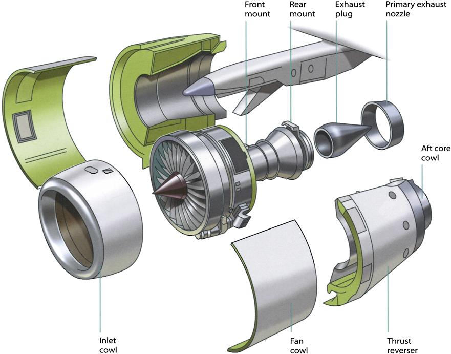
Nacelles are composed of an air intake, fan cowl doors, nozzle and tail cones, and, optionally, a thrust reverser. Typical civil turbofan nacelles are fitted under the wing on a pylon or fitted to the rear fuselage via a stub wing (Figure 13–14).
Two further nacelle options are the long (mixed exhaust) nacelle—the Trent 700—and the short (separate core and bypass jets) nacelle—Trent 800 and 500. Long nacelles can give a performance gain for some engines due to the mixing of the exhaust, and also have a greater acoustic treatment area, at the cost of extra weight and drag (Figures 13–15 and 13–16).


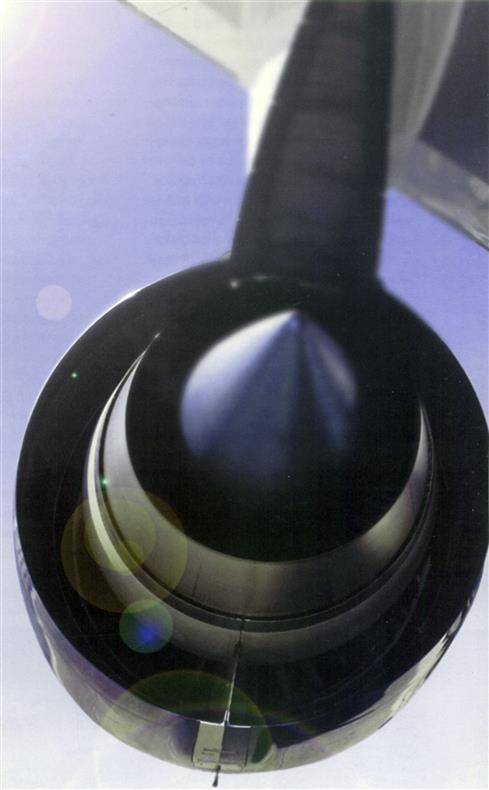
The Air Intake
The purpose of the intake of civil turbofan engines is to ensure that, under all operating conditions, the engine is supplied with the correct quantity of air, and that the air has sufficient flow uniformity to allow efficient and stable engine operation. The intake design is integrated into the engine nacelle to obtain the lowest level of drag at the operating design point, typically cruise.
For civil turbofans, the optimum intake configuration is a short, near-circular, pitot-type intake. This design is highly efficient for subsonic operation, as low levels of pressure loss are achieved under all operating conditions. Civil pitot intakes are suitable for wing and rear fuselage- mounted nacelles. For tri-jet configurations, s-duct intakes are a design option when the engine is buried in the rear fuselage (Figures 13–17 and 13–18).
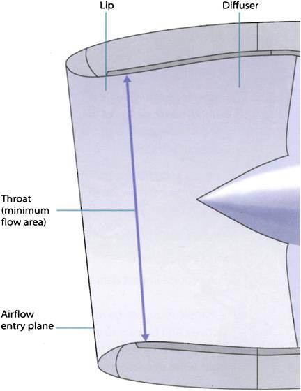
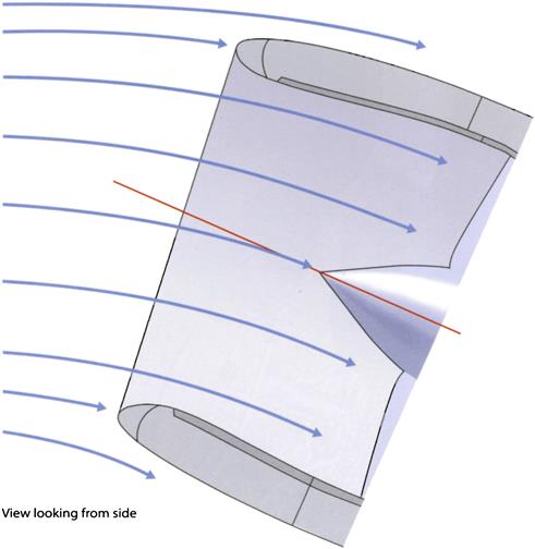
A pitot intake consists of two geometric regions, the “lip” and the “diffuser.” The forward section, the lip, is similar in section to an aerofoil and is shaped to guide the airflow into the engine under all operating conditions; the lip is also optimized to prevent flow separation under cross-wind and incidence operation. If flow separation occurs, this produces significant asymmetry in the total pressure within the intake increasing fan blade stresses and, in severe cases, may result in engine surge.
The internal surface of the lip is heated with hot air to ensure that there is no ice accretion, which could shed and damage the engine fan blades.
The lip contracts to a minimum area, sized for the engine flow requirements, known as the throat. Aft of the throat, the airflow passes into the diffuser where the flow area is increased up to the fan entry plane. The diffuser acts as a settling length to improve the uniformity of the airflow entering the fan. The diffuser section is lined with sound-absorbing, acoustic panels to reduce noise emissions.
Civil intake aerodynamic surface shapes are generated as mathematically defined 3D surfaces using CAD tools. The intake surface designs are evaluated and optimized using CFD codes, and the final design is validated by wind tunnel testing.
Before flight testing, to demonstrate that the intake and engine are fully compatible, further testing is conducted over a full range of flow conditions using a machine to simulate high cross-wind speeds.
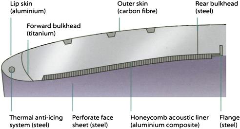
Intake construction is, typically, an aluminium intake lip for durability and compatibility with the ice protection system, a composite outer skin, an acoustic honeycomb inner barrel, and metal structure bulkheads. The intake is normally bolted onto the engine fan case. Some air intakes might not be circular due to ground clearance constraints and non-uniform accessory distribution around the fan case (Figure 13–19).
Following the retirement of Concorde, no immediate replacement existed for civil supersonic air travel. However, any future civil supersonic engines would probably use an external/internal compression intake with variable geometry similar to that used on Concorde and current military aircraft; such an intake provides higher efficiency at supersonic speed.
Thrust Reverser
The thrust reverser unit (TRU) has three key functions: to provide a continuous external aerodynamic surface for the nacelle; to provide a fan flowpath for the engine in forward thrust mode; and, of course, to reverse the exhaust flow after the aircraft touches down to assist with aircraft deceleration.
Generally, pilots and airlines want TRUs on jet engines. They can reduce aircraft landing distance, especially on wet and icy runways, while also reducing brake and tyre wear. They improve ground handling on wet and icy runways and taxiways—and improve rejected take-off margins in similar conditions. For military applications, TRUs provide the possibility of operating from bases with shorter runways giving greater operational flexibility.
In civil applications, no certification credit on landing distances is given for TRU fitment; an aircraft landing distance will be determined by the use of anti-lock brakes and aerodynamic drag devices such as flaps, airbrakes, and parachutes. TRUs are not essential for safe landing; however, they do provide increased safety.
There are four main types of TRU in use today:
• Translating sleeve and pivot door (fan air systems). These are used for large turbofan engines as the majority of the thrust is generated by the fan.
• Target door and pivot door (mixed stream systems). These are used for small, low bypass ratio engines as the split of fan and core thrust is more equal.
Most large fan engines have “C” duct TRUs that are split into two halves and hinged to the aircraft pylon, providing access to the engine core components. The TRU also provides a discrete fire zone containing fuel pipes, fuel nozzles, and combustion chambers.
Part of the thrust reverser optimization process includes ensuring that the hot air/gases neither impinge on the aircraft wing or fuselage nor are re-ingested into the engine intake, which could cause engine surge. It is also important to minimize any lift component from the thrust reverser in order to maximize braking efficiency.
Typically, most TRUs are constructed from carbon composite panels, aluminum structural beams, a metal firewall bulkhead, and a suitable thermal blanket (usually stainless steel) on the inner wall to ensure the epoxy in the carbon composite can withstand the combustion and turbine case temperatures.
Actuation of the translating sleeves or pivot doors is either hydraulic or electrical and three separate locks are provided to ensure there is no TRU deployment in flight. One of these locks will be separately operated, while the other two will be operated and controlled by the engine. For a short nacelle, the TRU also forms the cold, bypass air nozzle.
Nozzles and Tail Cones
There are two types of nacelle nozzle: the combined cold fan and hot gas nozzle, as seen, for example on the long nacelle of the Trent 700; and the hot gas nozzle, seen, for example, on the short nacelles of the Trent 500 and 800. Tail cones are standard and vary only in their length, cone angle, and whether or not they are acoustically treated. A combined nozzle assembly can reduce engine noise emissions by the fitting of acoustic honeycomb panels. Both combined and hot gas nozzles are fitted to the engine LP turbine flange. The tail cone is fitted to the turbine bearing housing at the engine center and provides a smooth increase in the hot gas exit transitional area (Figure 13–20).

Military Fuselage Intakes
Where, as in most military installations, the engine or engines are accommodated within the aircraft, the intakes are incorporated into either the fuselage or wing roots and become a much more integrated part of the aircraft design. As with the civil nacelle intake, the main requirement for such intakes is to supply air to the engine with the minimum loss of pressure and the least increase in aircraft drag. Similarly, for the compressor to operate efficiently and stably, the air delivered to the engine face must be of an acceptable quality in terms of velocity, angularity, and total pressure uniformity. On this form of intake, it is often this last requirement that becomes the most difficult to satisfy because of the physical constraints imposed by the more highly integrated installation and the need for the intake to operate over a wider range of flight speeds and aircraft attitudes.
A further, military-specific, requirement that is becoming increasingly important is for the intake to conform with the aircraft structure and obscure line-of-sight views of the engine face in such a way as to reduce the aircraft's observability by radar and infra-red detectors. This can lead to highly convoluted intake ducts and unusual intake opening shapes and locations.
Where the operational flight speed range is mainly subsonic, a pitot intake will normally offer the most efficient solution in terms of pressure recovery and drag. In a single-engined aircraft, this usually involves the use of a divided or bifurcated type of intake set on each side of the fuselage.
One disadvantage of the side-mounted type of intake is that, when the aircraft yaws, a loss of ram pressure occurs on one side of the intake (Figures 13–21 and 13–22).

This, together with a tendency for the flow over the intake lip to separate when the aircraft is flying at a nose-up incidence, will cause deterioration in both the pressure recovery and uniformity of the air presented to the engine face. The potential influence on engine performance (known as the intake/engine compatibility) demands understanding and attention.
A further example of a fuselage intake where ensuring intake engine compatibility is particularly challenging is the intake for the LiftFan® in the Joint Strike Fighter (F-35 JSF).
In this installation, the LiftFan is required to operate efficiently and stably behind an extremely short pitot intake at flight speeds of up to 460 kmh (250 knots) where the free-stream air is traveling at 90 degrees to the axis of the aircraft. This contrasts with a more normal installation, where conventional, much longer, civil and military intakes operate inside a 55 kmh (30 knot) crosswind limitation.
Despite careful intake design, including the use of a rear-mounted intake door to help turn the flow, the non-uniformity of the pressure and the angularity of the air presented to the fan face is more severe than that normally encountered in more conventional intake/engine installations (Figure 13–23).
To meet this challenge and ensure compatibility between LiftFan® and intake, novel techniques have had to be developed to replicate during ground test conditions seen in flight.
The pitot type of air intake becomes increasingly unsuitable at higher supersonic speeds due to the severity of the compression shockwave that forms and which progressively reduces the intake pressure recovery. A more suitable type of intake for these higher speeds is known as the external/internal compression intake, which improves the achievable pressure recovery by allowing the air to compress via a series of weaker shockwaves (Figure 13–24).

As aircraft speed increases still further, so also does the intake compression ratio, and it is necessary, at high Mach numbers, to have an air intake that includes variable geometry features to accommodate and control the changing volumes of air. The airflow velocities encountered in the higher speed range of the aircraft are much greater than the engine can efficiently use; therefore, the air velocity must be decreased between the intake and engine face. The angle of the variable throat area intake automatically varies with aircraft speed, and positions the shockwave to decrease the air velocity at the engine face and maintain maximum pressure recovery. This, coupled with auxiliary air doors used at static and very low speed conditions, allows an efficient match of the intake airflow to the engine demand over the full range of flight conditions.
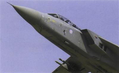
The Panavia Tornado has a twin-engined installation that retains the side mounting but uses an external/internal compression intake combined with a variable-throat area and auxiliary inlets (Figure 13–25).
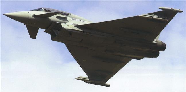
The Typhoon, a more agile aircraft, has a twin-engined installation with the intakes mounted under the fuselage (Figure 13–26). As well as avoiding the problems of fuselage shielding in yaw, this arrangement has the added advantage of using the under-fuselage surface to turn the air into the intake when maneuvering in a nose-up attitude. This not only off-loads the intake lips to avoid separation at high incidence, but also, at high flight speeds, pre-compresses the inlet air so improving pressure recovery. This intake also has a variable geometry bottom lip, which is used both to improve performance at high incidence and to achieve a better match of the intake capture area to the flight speed—avoiding the need for auxiliary inlets.
Stealth Aircraft
Enhanced survivability is an important emerging requirement for military aircraft. One way of meeting this requirement is through the reduction of aircraft “signatures” so the aircraft is less easily detected or traced by potential threats. This type of aircraft is known as a low observable, or “stealthy,” aircraft.
Reducing signature has considerable implications for the engine installation. The major signatures of interest are the radar cross-section (RCS), infra-red emissions—and, to a lesser extent, visibility and noise. The engine air inlet and exhaust duct designs of such stealthy aircraft are driven primarily by the need to achieve the requirements for a minimum signature without too great an impact on aerodynamic performance, weight, and cost. This results in designs that are visibly very different from those of conventional, non-stealthy aircraft.
Cavities, of which the engine air intake and exhaust duct are the largest, are a potentially large source of RCS emissions from a stealthy aircraft. The stealthy engine air inlet duct design obscures the engine fan face using either an inlet entry grill (as on the F-l17 Nighthawk), or a convoluted air inlet duct (for example, the F-35 JSF), or blocker vanes immediately upstream of the engine (F/A-18 E/F Super Hornet). These additional surfaces are typically treated with radar absorbent material.
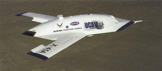
In addition, the engine air intake may itself be located so that it is shielded by the airframe from potential threat radars, and the inlet lips angled to align with the wing leading edges—for example, the X-45 Unmanned Combat Air Vehicle. The inlet duct is also designed to be free of any steps or gaps that may also contribute to the RCS (Figure 13–27).
Similar design features (with the exception of grills) may be used to control the RCS of the engine exhaust system, although the high temperature of the exhaust plume makes this more difficult.
One immediate consequence of the need to geometrically integrate the exhaust nozzle with the trailing edge of the airframe is a trend towards high aspect ratio rectangular nozzles—for example, the F/A-22 Raptor.
The engine exhaust system components and plume, being the hottest parts of the aircraft, dominate its infra-red signature. Consequently, an engine exhaust system designed for a stealthy aircraft is heavily compromised by the need both to shield the view into the hottest parts from the ground and to cool the exhaust plume by mixing it rapidly with the surrounding atmosphere—this will also help reduce jet exhaust noise. In addition, the exhaust system may employ aggressive cooling of the exhaust system components and the application of controlled emissivity materials, which make hot surfaces appear cooler than they actually are.
Flying Test Beds
A flying test bed (FTB) is usually a production aircraft converted to test a new engine type before the first flight of a new aircraft type. An FTB is fitted with data acquisition equipment and also has a number of simulated systems. A flying test bed requires a new test pylon or strut adaptor for the specific test engine; it may also need structural modifications (Figure 13–28).

Historically, before the development of altitude test facilities, a flying test bed was the only means of altitude testing a new engine. There are still specific tests that cannot be done using a ground-based altitude test facility: for example, various nacelle tests and g-load engine tests.
Airframe manufacturers and test pilots normally insist on FTBs for all engine programs, to evaluate engine operability with representative loads and inlet conditions before the first flight of the prototype aircraft.
Energy, (Power Generation), and Marine Installations
Energy and marine engine packages are generally supplied with all engine auxiliaries in place, leaving the builder of the application to provide starter power and fuel, water, and electrical connections.
Intake System
The intake system has to provide protection against snow, rain, and foreign object damage. Marine intakes are corrosion-resistant, often made of composite materials; industrial intakes require dust filters. The intake's large flow area reduces filter pressure loss and avoids ingesting snow or rain.
Cold, humid environments may require heating of the intake to prevent ice formation. Silencing is provided by flow splitters, consisting of sound absorbent material covered in a perforated sheet.
Enclosure
The enclosure provides weather protection (where appropriate), fire protection, and silencing. Ventilation is required to maintain a cooling flow past the engine. Engine accessories are often mounted within the enclosure but off the engine to allow quicker access and maintenance. Access is a key consideration for energy and marine installations to minimize downtime for maintenance. All enclosures have access panels. Some marine installations, like the WR-21, also allow engine removal via the intake. The design must consider issues such as safe working practices (for example, access control without entrapment), achieving a noise level below 80 dB at 1 m, and avoiding dangerous hot surfaces.
Although marine and industrial installations are not concerned with the flight speed aspects so important to the aero engine, size remains an issue. The WR-21 enclosure was designed so that it would fit in the footprint of existing marine engines.
Externals and the Engine Build Unit
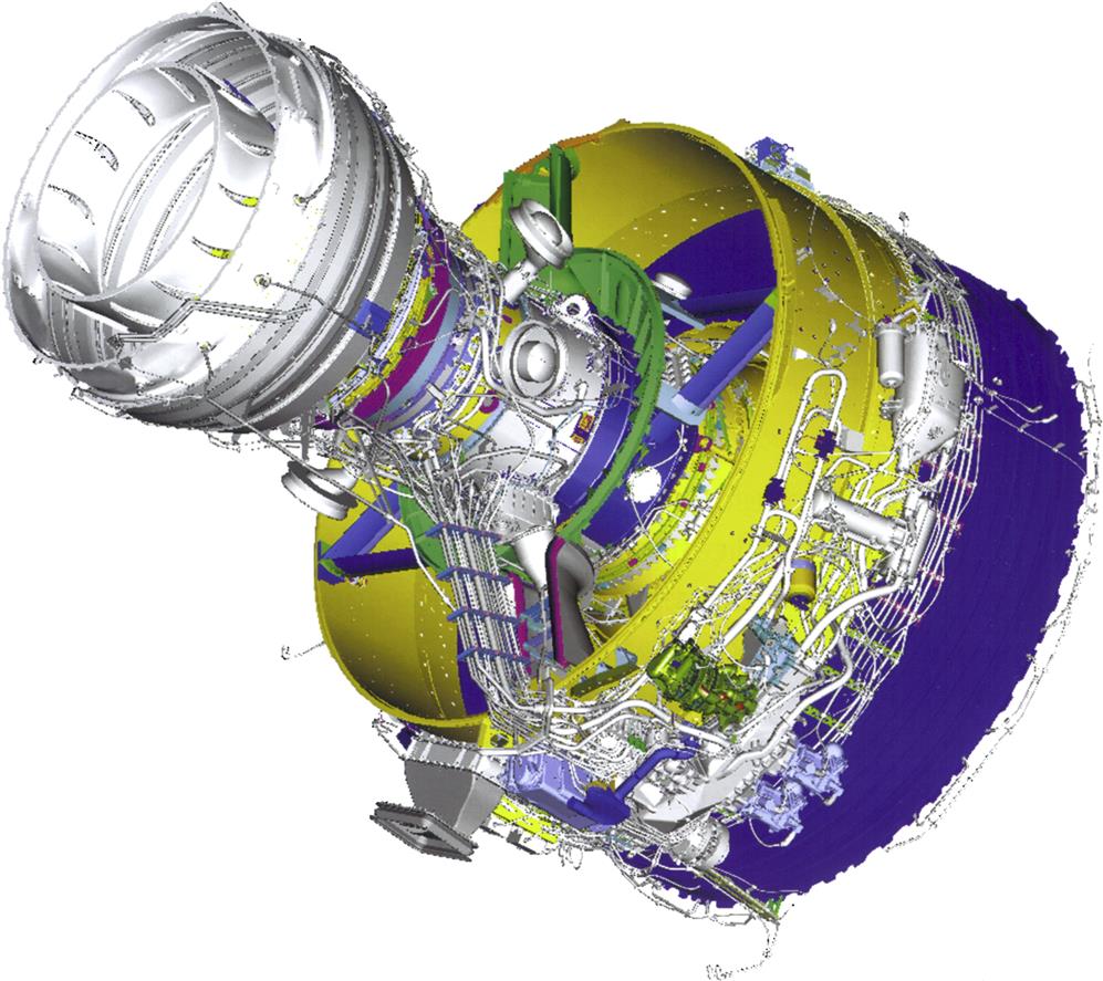
Engine externals are all the elements on a fully dressed engine that connect the engine accessories and controls:
The placement and routing of the engine externals is defined using a digital mock-up, which provides both static clash detection to assist positioning the externals and also dynamic clash detection to help demonstrate maintainability (Figure 13–29).
The engine build unit comprises the dressed engine with externals along with all the interfaces that need to be connected between the dressed engine and the airframe or nacelle:
Installation of Land-Based and Marine Engines
The installation of land-based and marine engines is different from that of aircraft engines in that they generally come with a base or skid on which the entire system is mounted. The system may be mechanical drive or power generation, on a ship, ferry, or offshore platform. The essential difference for offshore packages with the same gas turbine (as an equivalent land-based system) is that weight is curtailed as much as possible on offshore platforms.
On land applications, weight is not an issue. Generally, the base is grouted (filled with grout through grouting holes left in the skid surface). Care is taken to not leave any voids in the grout to lessen the chance of “soft feet” below a critical gearbox or bearing mount.
How much of an issue weight is on marine applications depends on the particular application and size of the marine vessel.
The main issue on land and at sea is space. The end user needs to ask a few questions:
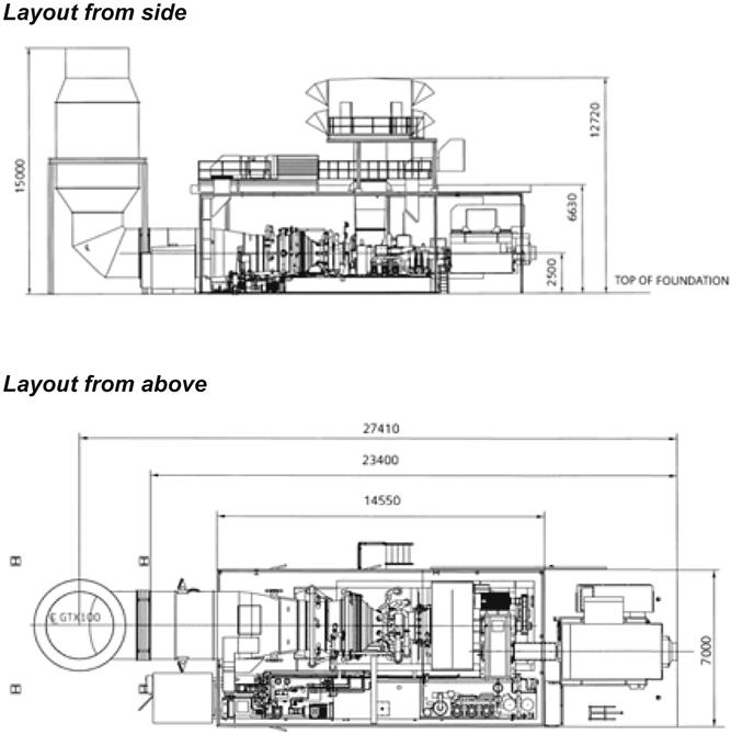
• How much space does the total installation/skid take up? (See Table 13–1 and Figure 13–30.)
• If weight is critical, what are the weights of all the system components?
• Is it likely that future additional propulsion requirements will need another gas turbine package?
• Can the skid be situated so that all plant components, such as inlet and outlet piping to the driven equipment in mechanical drive applications be routed so as to not cause excessive or cantilevered loads on the machinery flanges?
TABLE 13–1
SGT-100 Turbine for Power Generation (ISO) 4.35/4.70/5.05/5.25MW(e)
| Weights and Dimensions SGT-100 Generator Set | |
| Diagrams, Weights, and Dimensions are for Typical Standard Equipment | |
| Length (with package mounted controls) | 10.0 m (394 ins) |
| Length (without package mounted controls) | 8.0 m (315 ins) |
| Width | 2.40 m (94 ins) |
| Height (to top of enclosure) | 3.2 m (126 ins) |
| Weight | 35,460 kg (78,175 lbs) |
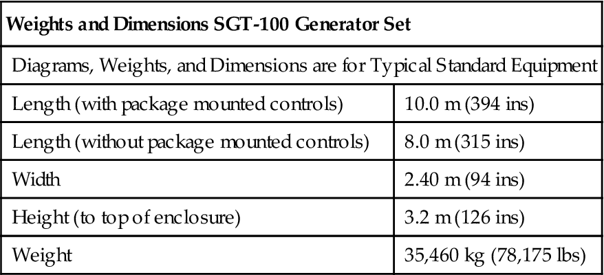
(Source: Siemens).
Other siting issues include items such as, does the gas turbine package need a “house” or will the system skid sit on the plant floor “as is?” Is the site appropriate for the potential needs of safety systems, such as risk posed by fluid moved by the driven equipment? My book Process Engineers Equipment Handbook (New York: McGraw-Hill, 2001) has a section on the risk of explosion on power generation gas turbine trains. The exception to permanent siting requirements is the mobile gas turbine package, which is frequently used by merchant power producers.