
The Thermodynamics of Water
As is well known, water may exist in both liquid and vapor phases over a wide temperature range. At a pressure of 1 bar and temperature of 100°C, water evaporates to steam if energy is supplied. This energy requirement is the latent heat of evaporation, and the process is known as boiling. At these conditions the volume increases by a factor of 1600. The boiling temperature rises as pressure increases, since a different change in volume then occurs. The inability to make good tea with water boiled on a mountain, which is then too cold, is well known. Conversely, if water is heated in a closed vessel the pressure and temperature both increase once boiling has begun.
Figure 10–26 shows schematically the properties of water in its three phases on a traditional temperature–entropy (T–S) diagram; for water it is known as the Mollier diagram. The characteristic “dome” shape defines the region through which evaporation may occur; inside this water exists as wet steam, a mixture of liquid and vapor. To the left of the dome only liquid water can exist, and to the right and above, only dry steam. Below 0°C liquid water cannot exist, only ice and an almost negligible vapor pressure due to sublimation. A temperature of 0°C is known as the triple point, where water may exist as ice, liquid, and steam. A pressure of 220.9 bar at 373.7°C is the apex of the “dome,” known as the critical point.
Figure 10–26 includes several lines of constant pressure. At the left-hand end of each line there is the saturated liquid line, onto which lines collapse for a substantial pressure range; pressure changes have only a small effect, as liquid water is almost entirely incompressible.
At fixed pressure, heat input to liquid water increases the temperature until it crosses the saturated liquid line, when the boiling temperature is reached. Further heat input causes evaporation at constant temperature, and hence movement to the right within the dome; the degree of evaporation is described by the dryness fraction or quality, which is the ratio of vapor to total by mass. The right-hand edge of the dome is the saturated vapor line, where evaporation is complete and the steam is dry. Beyond the dome still further heat input results in a temperature increase, and the dry steam becomes superheated. Superheating is applied as a term in various forms to the temperature difference from the saturation line at that pressure. If the pressure is raised above the critical point (22.9 bar) it is supercritical. Here evaporation from liquid water to steam cannot be distinguished by any step change in density, which instead decreases uniformly as temperature increases.
Steam is not a perfect gas in that enthalpy is dependent on pressure as well as temperature, due to attraction forces between the polarized water molecules. This effect is least at low density and high temperature.
For illustration, Figure 10–26 also includes the following:
Use of steam in power cycles utilizes the pressure increase when heating liquid water in an enclosed volume. There is no need for large work input, unlike for gas turbine cycles, as pressurizing incompressible feed water requires very little power. It is mainly for this reason that steam cycles were developed much earlier than gas turbines. Injected steam in a gas turbine remains in the superheated region all through the engine, whereas in some purely steam cycles it condenses. Examples include the back stages of a steam turbine running “wet,” and some reciprocating cycles utilizing the pressure reduction when steam is chilled.
There are different steam plant arrangements downstream of a gas turbine, including combined cycle, where a steam turbine produces additional shaft power.
• Formula 10.4 gives the enthalpy of saturated steam as a function of temperature.
• Formula 10.5 gives the evaporation temperature as a function of pressure.
• Formula 10.6 gives the partial pressure of water vapor as a function of its concentration.
• Formula 10.7 gives the enthalpy of liquid water as a function of temperature.
• Formula 10.10 gives the enthalpy of superheated and supercritical steam as a function of temperature and pressure.
Gas Turbine Performance Modeling and Test Data Analysis
The following sections present methods to model the individual effects occurring when water is encountered. These techniques are suitable both for predictions and test data analysis. Figure 10–27 presents a flowchart of how they interact; clearly many effects are common to several situations.
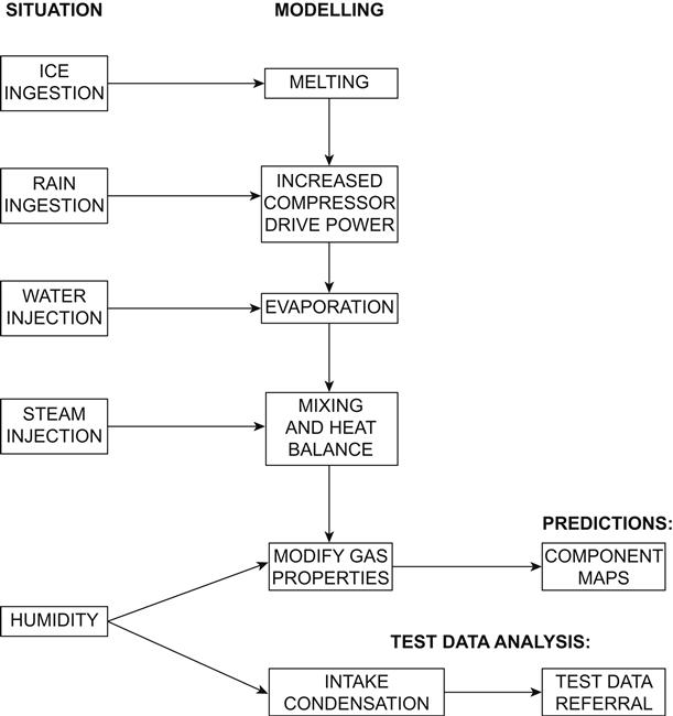
Ice and Melting
Accurate theoretical modeling is not practical; however, empiricism and approximation are sufficient to establish the impact on compressor efficiency and surge lines. Whether ice melts in the combustor or the compressor depends on residence time and particle size; extremes may be established by assuming each in turn; the difference in terms of the overall cycle may be small. Once ice has melted it becomes water droplets, which are discussed below. Formula 10.8 enables the heat absorption in melting to be calculated, from which the resulting air temperature reduction may then be simply evaluated.
Liquid Water and Evaporation
For the compressor the existing characteristic may still be used for the airflow, a parallel water stream must also be considered, and the compressor drive power increased accordingly.
Accelerating liquid water to some swirl velocity in each stage absorbs power, around 40–60% of the work that would be required if it reached the full mean blade speed; this power absorption may be approximated by applying Formula 10.9 for each stage before evaporation has occurred. Some evaporation may occur in the compressor, though for large flows much will pass through to the combustor; judgment or empiricism must be utilized regarding the relative quantities, as discussed earlier.
During evaporation in either the compressor or the combustor the heat absorbed must be calculated from the difference between Formula 10.7 and 10.10 with the total temperature and partial pressure. The gas path temperature reduction due to this must then be calculated via a mixing and heat balance calculation as described. The sample calculation illustrates the approach.
Steam Injection
The mixing and heat balance calculation is described below. For higher steam flows giving more than 10% WAR (the ratio of water to dry air, by mass) the turbine calculations should employ steam formulae. Modeling the HRSG must consider several key points:
• Steam formulae must be used on the steam side, including the evaporation of the liquid water supplied.
• Steam formulae may also be required on the gas side, depending on the steam concentration.
• Enthalpy changes on the steam and gas sides must be equal.
• Design minimum levels of the main temperature differences must be maintained.
• Steam delivery pressure must be some specified amount above that at the engine injection point.
To meet the last two criteria the steam delivery temperature may vary as matching guesses in a matching model, and/or the rate of steam production.
Mixing and Heat Balance
Prior to evaporation the ice/water and air streams are considered in parallel. Afterwards, the latent heat absorption has been accounted for, the streams must be combined via a mixing and heat balance calculation:
• The changes in enthalpy for each stream must be equal and opposite. The sample calculation illustrates this process.
• Total pressure is normally assumed not to change during mixing, as the steam is normally a small fraction of the total flow.
• Gas properties downstream of the mixing plane should be adjusted by one of the methods described next.
Such calculations may require iteration, if so they become simply an extension of a “matching” model
Gas Properties
Three methods for adjusting gas properties to account the presence of water vapor for thermodynamic calculations are shown below. They are listed in order of increasing accuracy:
1. Using Formulae 10.1–10.3, which represent the factors to be applied to gas properties versus water vapor concentration as per Table 10–3. This method assumes that pressure does not change enthalpy (i.e., that water vapor is a perfect gas), and that the gas property ratios are not affected by temperature; it is adequate for first-order calculations.
2. Using the various formulae for specific heats given in Chapter 19. In all cases the overall specific heat should be obtained by averaging the gas constituents and additional water vapor on a molar basis, and the ratio of specific heats gamma is then easily derived. This method still assumes that water vapor is a perfect gas; however, where vapor content is less than 10% the error incurred is negligible; this method is the most widely used.
3. Evaluating CP for the additional water from Formula 10.11, which does not assume a perfect gas and accounts for the effect of pressure on steam properties. CP calculated in this fashion will be as per steam tables. The gas constant and ratio of specific heats are then derived as per method 2. This is the most rigorous method, and should be used for water content exceeding 10%.
Component Maps
Where there is water vapor but no liquid or ice present, component maps are normally read via the simplified quasi-non-dimensional groups. These groups relate flow, speed, pressure, and temperature and use implicit “dry air” values of the fundamental gas properties, gamma and R. As described earlier, water vapor changes these properties, hence with water vapor present the full forms of the non-dimensional groups must be recognized.
When water or ice are present, the use of the maps must incorporate gamma and R corresponding to 100% RH, or more often their ratios to the values for dry air. This is in addition to the calculations described in this section, where the water/ice is considered as a separate parallel stream. The changes in gas properties account for the effect on both the independent parameters against which the maps are tabulated, and on the dependent parameters returned from the map read. Evaporation within compressors produces an intercooling effect which is specific to the compressor design. Given the uncertainty of evaporation location, it is usual to simply retain the same compressor map.
Test Data
To understand engine behavior on test the effects of humidity must be accounted. These are due to the variation in gas properties, and potentially also to condensation. The first step is accurate humidity measurement at test conditions.
Non-Dimensional Corrections
Engine test data are referred to standard conditions via non-dimensional groups, to allow valid comparison of prediction and other test data. For humid conditions revised gas properties CP, gamma and R are evaluated as described above.
Rigorous Modeling
No attempt is made to correct test data to standard conditions. Instead it is compared with expectation via a rigorous thermodynamic prediction model, run at the tested conditions. The modeling accounts for effects of humidity on gas properties and hence on component maps, thermodynamic processes, etc. as described above. This applies equally to analysis of component performance changes via matching methods.
Intake Condensation
As stated the concentration and properties (hydrophobic, charged, etc.) of particles that may cause intake condensation cannot be determined. A theoretical, maximum rate at which it could occur may be calculated from relative humidity and intake Mach number. Formula 10.12 provides an approximate method. There are then two possible approaches, listed in order of increasing accuracy:
1. Assume condensation occurs at half the theoretical rate.
2. Correlate measured engine performance versus theoretical maximum rate. This would be done over a series of different engines, which also have build and manufacturing variabilities. Coefficients would be determined for the effects on main measured parameters, as the mean slopes of plots versus the theoretical temperature rise for measured ambient conditions. Comparison of engines would involve correction back to the same theoretical temperature rise using these coefficients.
Directly measuring the actual rate of condensation during a test would clearly be preferable; however, at the time of writing no absolutely successful technique has been demonstrated.
Intercooler Condensation
The control algorithms should adjust the degree of intercooling to prevent this. The requirement is therefore accurate modeling of the control action, which depends on the specific system. There should be no need to make adjustments to test data.
Formulae
Formula 10.1. Specific Heats Factor for Moist Air = fn(Water Air Ratio)
(i) CPfac is the ratio of CP for moist air to that for dry air.
(ii) WAR.molar is the ratio of water to dry air, by number of moles.
(iii) CPW, CPA are the specific heats of water and dry air.
(iv) WAR is the ratio of water to dry air, by mass.
(v) 18.015, 28.96 are the molecular weights of water and dry air respectively.
Formula 10.2. Gas Constant Factor for Moist Air = fn(Water Air Ratio)
(i) Rfac is the ratio of R for moist air to that for dry air.
(ii) Ro is the universal gas constant, 8.31 kJ/mole K.
(iii) MW is the molecular weight of moist air.
(iv) RA is the gas constant of dry air, 0.28705 kJ/kg K.
(v) WAR is the ratio of water to dry air, by mass.
(vi) 18.015, 28.96 are the molecular weights of water and dry air respectively.
Formula 10.3. Gamma Factor for Moist Air = fn(Water Air Ratio)
(i) GAMMAfac is the ratio of GAMMA for moist air to that for dry air.
(ii) WAR.molar is the ratio of water to dry air, by number of moles.
(iii) GAMMAW, GAMMAA are the ratio of specific heats for water and dry air.
(iv) WAR is the ratio of water to dry air, by mass.
(v) 18.015, 28.96 are the molecular weights of water and dry air respectively.
Formula 10.4. Enthalpy of Saturated Steam (kJ/kg) = fn[Temperature (°C)]
Accuracy is within 0.6%, range is 0–370°C.
Formula 10.5. Temperature Level of Evaporation (°C) = fn[Pressure(bar)]
For P = 1 to 25 bar:
For P = 25 to 210.5 bar:
Accuracy is within 0.5°C.
Formula 10.6. Partial Pressure of Water Vapor in Moist Air (Bar) = fn[Specific Humidity, Pressure (Bar)]
(i) Pw is water vapor partial pressure.
(ii) SH is specific humidity, kg water vapor per kg dry air.
(iii) 0.622 is the ratio of molecular weights of water and dry air.
Formula 10.7. Enthalpy of Liquid Water (kJ/kg) = fn[Temperature (°C)]
Formula 10.8. Latent Heat of Melting Ice (kJ/kg)
Formula 10.9. Work on Liquid Water in Compressor (W) = fn[Water Flow (kg/s), Mean Blade Speed (m/s)]
For an axial compressor this work is done in each stage.
Formula 10.10. Enthalpy of Dry Steam (kJ/kg) = fn[Temperature (°C), Pressure (Bar)]
Superheated:
Supercritical:

Formula 10.11. Specific Heat of Steam (kJ/kg K) = fn[Temperature (°C), Enthalpy (kJ/kg)]
Formula 10.12. Theoretical Maximum Rate of Condensation = fn(Temperature, Pressure, Mach Number, Humidity)
The following outlines an approximate method:
• Calculate initial total enthalpy for air and water vapor using T0 and SH.
• For the case of no condensation, calculate local static temperature after flow acceleration using T0 and M.
• Calculate increased local static temperature TS after condensation as above + TRISE.
• Calculate local static pressure after flow acceleration using P0 and M.
• Calculate partial pressure of water vapor from Formula 10.11.
• Calculate saturated value of water vapor partial pressure. This also gives specific humidity at saturation, SHsat.
• Calculate amount of condensed water to reduce the partial pressure of water vapor to the saturated value.
• Calculate enthalpy of air and remaining water vapor using T0 + TRISE and SHsat.
• Calculate enthalpy of condensed liquid water from Formula 10.7.
• Iterate on TRISE until enthalpies balance before and after condensation.
The main approximation is to neglect the loss in total pressure that occurs due to the momentum change when heat release causes an increase in flow velocity.
Sample Calculations
Ingested rain evaporates within a compressor. Determine (i) the possible range of power absorption due to varying amounts of work done on the liquid water, (ii) gas conditions downstream and (iii) the variation of exit temperature resulting from changing the assumptions about how many stages the liquid water absorbs work in.
Conditions are as below:
Blade speed (m/s) 700
Compressor PR 5
Compressor isentropic efficiency 0.86
Number of compressor stages 6
| Water | Air | |
| Temperature (K) | 293 | 293 |
| Pressure (kPa) | 100 | 100 |
| Mass flow (kg/s) | 1.0 | 100 |
From Formula 10.9 the work done in each compressor stage is DPW = 0.5 × Wwater × U2:
Since evaporation requires some temperature increase, work will be done in one stage at the very least. The maximum number of stages would be the full six:
Compressor temperature rise for dry air. Ignore changes in compressor performance due to intercooling.
Evaporation Calculation
Calculate enthalpy of ingested water using Formula 10.7:
Calculate partial pressure of steam at compressor exit using Formula 10.6:
Calculate enthalpy of steam using Formula 10.10 for superheated steam. Add work done on liquid water in first compressor stage.
Now calculate change in air enthalpy due to heat absorbed by the water:
Mixing Sum Iterate to make QUair = QUwater, using either inbuilt spreadsheet functions or “manual” updates. Converged solution gives Tmix = 193.5°C.
Recall work done on liquid water per stage = 245 kW.
Repeat above iteration with QUair = QUwater + 245:
Hence a difference of one stage changes the mixed temperature by 2.4 K; five stages would change it by 12 K.
Note: For this small water concentration the presence of the water could have been neglected and the temperature change found by considering the air alone.
At this point, it is useful to consider a case study of testing/verification of a high performance gas turbine. In this case, the US DOE is funding work that raises the efficiency level of gas turbines made by OEMs in this US DOE program. Key objectives that stem from increased efficiency are fuel conservation and emissions reduction.
Case Study 1: The W501G Testing and Validation in the Siemens Westinghouse Advanced Turbine Systems Program6
Note to readers
As per the footnote7, readers can note that this paper was written when Siemens was Siemens Westinghouse. As always in this book, even if an OEM has altered their name or ownership, if a technology or case study is still relevant today, then I will include the original name under which the work or paper was released. To those who study the nuances of design, this can have relevance in that the Siemens Westinghouse partnership brought with it, some technology that had originated with Westinghouse. Further Westinghouse had earlier associations with MHI (Mitsubishi) and some of its components bore evidence of same.
The Siemens Westinghouse Advanced Turbine System (ATS) has the ultimate goal of achieving greater than 60% LHV-based net plant thermal efficiency, less than 10 parts per million NOx emissions, a 10% reduction in cost of electricity, and reliability-availability-maintainability (RAM) equivalent to modern advanced power generation systems. The ATS program, which is supported by the US DOE, introduces advanced technologies in three evolutionary steps to minimize risks and to increase the net benefits of the program. The W501Q, the first step in the ATS engine introduction incorporates many ATS technologies such as closed-loop steam cooling, advanced compressor design, and high temperature materials. The lead unit has completed full-load testing at the City of Lakeland McIntosh #5 site in Lakeland, FL, and has produced power and revenue for Lakeland Electric since May 2000. Results from the testing are presented and future developments are discussed. Building on the current W501Q advancements will include steam-cooled turbine vanes and leakage enhancements. Continuing this low risk step-wise introduction of new technology, the W501ATS engine adds further advanced designs that achieve the program objectives. Siemens Westinghouse is also infusing ATS technologies into its mature frames in both new units and service upgrades to maximize the benefit of the program.
The Advanced Turbine Systems Program (ATS) funded by the US Department of Energy, Office of Fossil Energy, is an ambitious multi-year effort whose goal is to develop technologies necessary for achieving significant increase in natural gas-fired power generation plant efficiency, a decrease in cost of electricity, and a reduction in harmful emissions, while maintaining the current state-of-the-art reliability, availability, and maintainability (RAM) levels. This three-phase technology development and demonstration program was started in 1992 and was completed in 2001.
To achieve the ATS Program goals for performance, emissions, electricity cost, and mechanical reliability, significant advancements were required in key technologies applied in gas turbine design. Successful developments were carried out in technologies relating to aerodynamics, combustion, cooling, sealing, materials, and coatings.
The W501ATS engine incorporates new technologies, as well as proven design features developed over the last 50 years and employed successfully in the W501 series of heavy-duty industrial and utility engines. These proven design features include single-shaft, two-bearing rotor; cold-end generator drive; compressor blade rings; low-alloy-steel rotor discs; curvic-clutched turbine rotor; four-stage turbine; cooled and filtered rotor cooling air; single first-stage turbine vane segments; tangential exhaust struts; and individual combustor baskets. The W501ATS engine is the latest in successful designs evolving from proven predecessors such as the 186 MW W501F and the 253 MW W501.
Evolutionary Approach
Siemens Westinghouse solicits input from an industry advisory panel comprised of members from major US and international utilities and independent power producers. Based on the input from this panel and market analyses, Siemens Westinghouse is pursuing an evolutionary introduction of the ATS, which incorporates ATS technology in stages culminating in an engine that meets or exceeds all of the program objectives. This approach has two main advantages. Firstly, the evolutionary approach mitigates the risk associated with introducing multiple, advanced technologies simultaneously. Secondly, the early introduction of ATS technology expands and accelerates the benefit of the program, as compared with limiting the technologies to only the ATS engine.
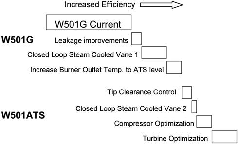
The evolutionary approach is shown schematically in Figure 10–28. Firstly, the introduction of the ATS frame begins with the W50IG. Many ATS technologies are incorporated in the W501G and are discussed later. Secondly, from the initial W501Q future enhancement include steam-cooled turbine vanes, leakage improvements, and increased burner temperature. Thirdly, the W501ATS engine evolves from the W501Q which reduces development risks through early demonstration of many critical technologies.
Siemens Westinghouse is further expanding the benefits of the ATS program by introducing ATS-developed technologies into its mature product lines. For example, the latest W501F incorporates ATS-developed brush seals, coatings, and compressor technology. Furthermore, many of these technologies can be retrofitted into operating units.
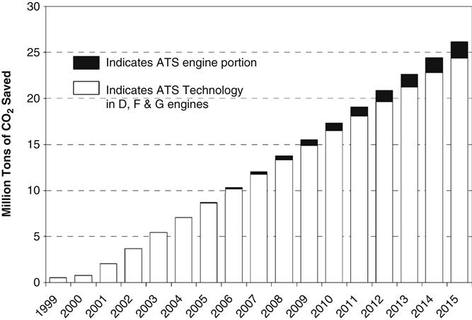
Because the F frame accounts for a majority of current new unit sales, this infusion of technology yields significant savings in fuel and emissions. Figure 10–29 shows the total impact of Siemens Westinghouse ATS technology on CO2 emissions. Note that much of the net benefit is the result of Siemens Westinghouse’s approach of expediting and expanding ATS technology through evolutionary introduction and infusion into mature frames.
ATS Technology in Operation
The W501G is the first major introduction of the ATS technology. The W501G incorporates the following ATS engine features:
ATS Advanced 3D Compressor
The W501G incorporates the first 16 stages of the 27:1 pressure ratio, 19-stage, ATS compressor with slight modification of the last 3 stages, and with vanes 1 and 2 fixed instead of variable. As a result, the W501G operates the ATS mass flow of 558 kg/sec (1230 lbs./sec), but at a pressure ratio of 19:1—optimized for the G cycle performance.
The design is based on three-dimensional inviscid flow analyses and on custom-designed, controlled-diffusion airfoil shapes. Controlled-diffusion airfoil design technology has been successfully applied in the aircraft industry for many years. The mechanical integrity of each stationary and rotating airfoil was verified by finite element analyses to satisfy steady stress and endurance strength criteria. Each airfoil was tuned to avoid potentially harmful resonant frequencies.
To verify the aerodynamic performance and mechanical integrity of the new high-pressure ratio design, the full-scale W501ATS compressor was manufactured and tested in 1997 at a specially-designed facility at the US Navy Base in Philadelphia. To reduce the required power to the 25 MW available at the test facility, the compressor test was carried out at subatmospheric inlet conditions.
The ATS-developed compressor technology has also been retrofitted into the W501F product line. Using the analytical techniques developed and proven in the ATS program, the W501F compressor was upgraded in the latest improvement to this successful frame. This advanced compressor is utilized on new W501F units. In addition, the redesigned compressor can be retrofitted to any 42 W501Fs that were built with the original W501F compressor. Applying this ATS technology to the W501F expands the benefit of the ATS program since the W501F compromises more than 70% of future units that are sold or on order at Siemens Westinghouse.
Brush Seals and Abradable Coatings
To minimize air leakage, as well as hot gas ingestion into turbine disc cavities, brush seals were incorporated into the W501ATS engine design at several locations: under the compressor diaphragms, at the turbine disc front, under turbine rims, and at the turbine interstages. Tests were carried out on test rigs for the different brush seal locations to develop effective, rugged, reliable, and long life brush seal systems. At the Philadelphia US Navy Base, full-scale brush seals were tested as part of the ATS compressor test, which verified the brush seal low leakage and wear characteristics.
To date, ATS-developed brush seals have been successfully incorporated and operated in W501G and later W501F product lines. Pre- and post-upgrade tests have demonstrated performance improvement in retrofit applications.
Considerable performance benefits can be obtained by reducing compressor and turbine blade tip clearances. Abradable coatings permit tip clearances to be minimized without fear of damaging hardware, and they provide more uniform tip clearances circumferentially. Abradable coatings, identified for compressor and turbine applications, were tested to determine abradability, tip-to-seal wear rate, and erosion characteristics. These ATS-developed abradable coatings have been incorporated into the W501F and W501G compressor and front turbine stages (1 and 2). The later turbine stages (3 and 4) employ shrouded blades with honeycomb seals.
Closed-Loop Steam Cooling
Using closed-loop steam cooling on transitions and turbine stationary components has two advantages. First, more compressor delivery air is available for premixing with the fuel gas in the combustor hot end. This allows very lean premixed combustion and makes possible the restriction of NOx emissions to single digits. Second, closed-loop steam cooling significantly improves cycle efficiency by reducing the amount of chargeable air used for cooling and sealing.
The ATS transitions, which duct the hot combustor exit gases to the turbine inlet, are closed-loop steam cooled with air as an alternate coolant at part load. Steam enters the engine through four external connections and is routed to each transition supply manifold through internal piping. The supply manifold feeds the steam to an internal wall cooling circuit. After cooling the transition walls, the steam is collected in an exhaust manifold and ducted out of the engine. The W501G employs the ATS transition.
High-Temperature Thermal Barrier Coatings
Thermal barrier coatings (TBC) are an integral part of the W501ATS engine design. A development program is in progress to develop an advanced bond coat/TBC system with a projected service life of more than 24,000 hours. Different bond coats and ceramic materials were evaluated under accelerated oxidation test conditions and down selected. An advanced bond coat/TBC system mechanical integrity and durability was demonstrated in more than 24,000 hours of cyclic testing at 1010°C (1850°F). This advanced bond/coat TBC system has been incorporated on the W501G Row 1 and 2 blades. This coating will improve both the life and durability of these parts, and it can potentially improve future engine performance by reducing the amount of cooling air required.
ATS Row 4 Turbine Blade
The 25% increase in engine mass flow, compared with the baseline F class machines, necessitated an advanced design Row 4 turbine blade to avoid increasing turbine exhaust losses. The ATS Row 4 blade is an uncooled, interlocked, Z-shrouded, cast airfoil. Because the W501G employs the ATS compressor and associated mass flow, this blade was first introduced on the W501G. On the first W501G at the City of Lakeland McIntosh #5 site, the blade was instrumented with vibration monitors and strain gauge telemetry. In testing to date the blade has performed as predicted in both aerodynamic performance and mechanical strength.
Engine Test Results
The first W501G was ignited in April 1999, at the City of Lakeland MacIntosh #5 site. The unit has undergone extensive testing and verification. Since March 2000, the customer has dispatched the unit based on power demands. This lead W501G engine has accumulated over 239 starts and 850 fired hours as of November 2000. Currently, the unit operates in a simple cycle mode with a once-through steam generator for cooling steam production. Construction of the combined-cycle plant is under way and will complete in 2002. The W501G Design Plant Performance is shown in Table 10–7.
TABLE 10–7
W501G Design Plant Performance
| Power, net MW | 253 |
| Heat Rate | |
| kJ/kW-hr | 6206 |
| BTU/kW-hr | 5884 |
| Airflow | |
| kg/sec | 558 |
| lbs/sec | 1230 |
| Pressure ratio | 19.5:1 |
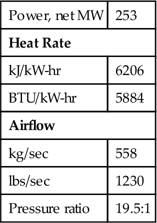
(Source: Siemens.)
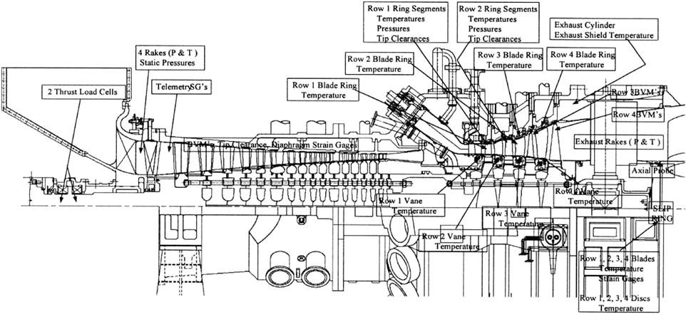
The test program included over 3000 sensors and measured parameters. An engine schematic showing the various sensors is shown in Figure 10–30. The test program consisted of two phases—emissions/performance mapping and thermal paint testing. The emissions/performance mapping phase tested targeted combustion system variables and provided engine performance mapping for different operating conditions such as IGV position and exhaust temperature.
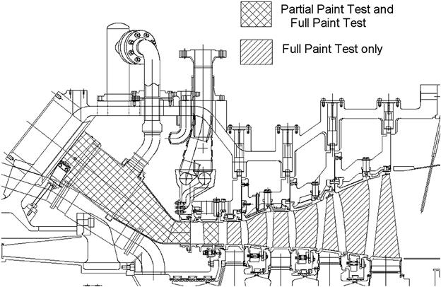
Following the initial testing, turbine flowpath components and combustion components were prepared with thermally reactive paint and installed. The thermally reactive paint changes color based on exposed temperature. This method is used extensively in aero engine validation since it provides a complete and accurate temperature map of the components at operating conditions. To react the thermal paint, the engine was ramped up to full load, run for approximately 5 minutes at full load and then shut down. The thermal paint test was conducted in two phases. In July 2000, the transitions and Row 1 vanes were painted and tested. These components are removable without a major cover lift. In October 2000, a full paint test was conducted which included all turbine blades and vanes and areas of the rotor. Figure 10–31 shows the scope of the painted components. In addition to the base design, several components were installed with different cooling schemes. The different schemes were tested to evaluate possible cooling flow reductions and component durability enhancements. Both tests were conducted successfully and results are being evaluated.
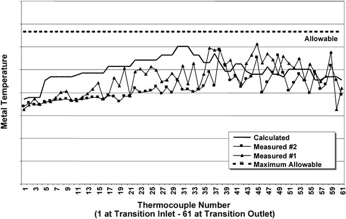
The testing validated the closed-loop steam cooling in a commercial application. The steam turbine temperatures were measured under both air cooling at part load before steam quality was achieved and under full-load closed-loop steam cooling. The testing at Lakeland has confirmed the ability to switch between steam and alternate air cooling. As anticipated, actual measured metal temperatures are lower in the new closed-loop steam-cooled design than in existing open-loop air-cooled design. The temperatures were measured along the length of the transition and are shown in Figure 10–32.
Operating Experience
During testing and validation, two significant issues were encountered and resolved: vibration on front compressor diaphragms and combustor high frequency dynamics (see Figures 10–33 and 10–34).
The front compressor diaphragms on stages 1, 2, and 3 exhibited signs of distress after approximately 200 hours of operation. A root cause investigation identified high cycle fatigue due to high excitation of airfoils combined with residual stresses and high stress concentration factors. A minor design modification was initially applied and validated in the W501G at the City of Lakeland McIntosh #5 site. Additional dynamic strain gauges were applied for monitoring dynamic stresses. The redesign has operated successfully for a total of over 1000 hours in W501G engines. A full cover lift and NDE inspection at the City of Lakeland McIntosh #5 site was completed and no operating restrictions are in effect.
During testing, high combustion dynamics were observed at approximately 2200 Hz causing distress to combustion system components. A root cause investigation identified insufficient aerodynamic damping as result of closed-loop steam cooling of the transition. To eliminate the dynamics, resonators tuned for 2200 Hz dynamics were added to the transitions. The resonator design was first tested and validated at the Siemens Westinghouse high-pressure combustor test facility at Arnold Engineering Development Center in Tullahoma, TN. Subsequently, the modified transitions were validated at the city of Lakeland and successfully dampened the combustor dynamics. As an added precaution, a combustor dynamics monitor has been added as standard supervisory instrumentation as part of the digital control system. In the event that combustor dynamics occur, the system will automatically adjust the engine operation to eliminate the dynamics and avoid distress on the components. Validation continues with alternate fuel sources.
Development Activities
Steam-Cooled Vane
Development activities are focused on extending the W501G frame to ATS efficiencies through the introduction of additional technology advancements. The next major step will add a thin-walled, closed-loop, steam-cooled Row 1 turbine vane to the W501G. The steam-cooled vane will extend the benefits of the steam-cooled transition by eliminating most cooling air from the Row 1 vane. The result will be a combination of increased rotor inlet temperature and decreased burner outlet temperature. The benefit will be improved efficiency and reduced NOx. Single-crystal casting trials have been successfully completed at PCC Airfoils, Inc. in Mentor, Ohio.
The ATS steam-cooled vane will be first tested in an engine sector rig. The test rig consists of a full-scale combustor basket and transition and a 1⁄16th-sector vessel, which will operate up to full ATS pressures and temperatures. The rig will be located at Arnold Engineering Development Center at the Arnold Air Force Base in Tennessee. The vane will be instrumented to verify analytical predictions of metal temperatures, heat transfer coefficients, and stress.
After validation in the 1⁄16th-sector rig, the vane will be retrofitted into a W501G. A comprehensive test program will verify vane performance and improved plant performance. Test parameters will include vane metal temperature, stress, and steam temperatures.
Coatings
Thermal barrier coatings (TBC) are an integral part of the W501ATS engine design. A development program is in progress to develop an advanced bond coat/TBC system with a projected service life of more than 24,000 hours. Different bond coats and ceramic materials were evaluated under accelerated oxidation test conditions and down selected. The mechanical integrity and durability of an advanced bond coat/TBC system was demonstrated in more than 24,000 hours of cyclic testing at 1010°C (1850°F).
Under a related program, DOE-Oak Ridge National Laboratory (Contract DE-ACO5-95OR22242), new ceramic compositions and TBC concepts were identified which have a sintering resistance and phase stability superiorted to that of 8YSZ TBC. These compositions and concepts are being further optimized and will be transferred to components for an 8000 hr engine demonstration under a DOE-Chicago contract DE-FCO2-000H11048.
Performance Optimization Case Histories and Discussion
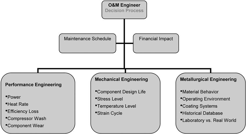
In this book’s introduction, the author points out that maintenance, repair, and overhaul (MR&O) works best in planned synergy with engine condition monitoring (ECMS), performance analysis (PA, in some cases managed as a component of ECMS), and performance (recovery or otherwise) testing. One may regard ECMS and MR&O as “chicken and egg” in that either may happen first in a plant’s life, depending on the designer’s grasp of maintenance philosophies. In Chapter 12, Maintenance, Repair, and Overhaul, the author discusses maintenance philosophies. To reiterate briefly those are
• Reactive (do nothing until failure occurs).
• Preventive (do only what the OEM suggests in his manual, and if it does not work, you can blame the OEM, maybe).
• Predictive, also called on condition (keep an eye on the system via a comprehensive ECMS).
Yet another option, of which this author is not fond, considering the power unleashed in the case of catastrophic failure, such a turbomachinery case rupture, is “run to failure.”
Nevertheless this has been done by operators such as those in refinery service who intend that their plant be shut down and abandoned when they run out of product to process or incur a failure in a critical plant location, whichever comes first.
In larger organizations today, the ECMS and MR&O functions are typically done by different people. Further, within MR&O, there are maintenance engineers, R&O engineers, and metallurgists. It then becomes critical that these various individuals communicate well. Since they may be working in branches all over the world, the Internet, their intranet, and common file platforms (for shared files) become the grammar for their language.
Performance optimization when retrofit design is involved, is unique to each application. For instance, one might agree that steam injection can (among other benefits) boost the power developed by a gas turbine. However, the actual retrofit is designed for an existing installation. However, once a retrofit is successful, it may be incorporated by the OEM or independent designers into future installations involving the same model of gas turbine and accessory systems.
Most of the gas turbine installations in the world were built before oil soared above $70 a barrel in 2006. So retrofits for performance optimization will probably increase.
The best way to illustrate some of the potential ways gas turbine performance may be optimized is by using case studies. This is one area where they are more suitable than overall general theory, because as the reader will note, different aspects of highly specific theory may be relevant in each case.
Power generation remains and will continue as the largest industry sector in the world for a few decades, perhaps longer. It is therefore appropriate that many of the examples selected belong to that industry. Due to the relatively large real estate involved in large-scale power production, this sector also has the most physical space to add economizers, additional HRSG capacity and so forth.
In summary, the cases deal with different optimization strategies as follows:
Case 2. A Systems Approach to Hot Section Component Life Management. This case discusses extension of hot section component lives and outlines work done by a metallurgical repair facility.
Case 3. Strategies for Integration of Advanced Gas and Steam Turbines in Power Generation Applications. This case was written by an EPC contractor held responsible for the performance of a powerplant at turnover to a client. It discusses ascertaining that the OEM power generation package and components are delivered according to specification and if not, how short they fall as well as “tweaks” to the operational system that can help attain on-performance curve operation.
Case 4. A Study on the Life Cycle Impact of Steam Injection deals with the benefits of steam injection on an LM6000 (a CF6-80C2 aeroderivative). This case is written by a metallurgical repair facility. The LM6000 is different from most other aeroderivatives in that it is controlled not just by low-pressure TIT and compressor discharge temperature.
Case 5. Augmentation of Gas Turbine Power Output by Steam Injection. This case was authored by an OEM.
Case 6. Integrating Gas Turbines in Power and Cogeneration Applications. Written by an EPC contractor, this case discusses primarily “F” class gas turbines.
Case 7. An Integrated Combined-Cycle Plant Design that Provides Fast Start Capability at Base-Load. Written by an OEM, this case is of relevance to power dispatchers. (The simple cycle GT starts faster than a traditional steam turbine because of the boiler startup period.)
Case 8. Challenges in the Design of High Load Cycling Operation for Combined-Cycle Power Plants, This case deals with the same issue as the preceding case, but this is written from an EPC contractor’s viewpoint.
Case Study 2: A Systems Approach to Hot Section Component Life Management8
One approach that has been successfully employed to more accurately identify the usable life of turbine blades is to perform metallurgical testing on a representative sample blade during major overhauls. This allows the extent of degradation by oxidation, corrosion, microstructural over aging, and creep occurring under the specific operating conditions of the individual engine to be characterized. On the basis of this testing, the serviceability of the balance of the blade set can be evaluated and an estimate of remaining life can be made.
In instances where unacceptable lives are obtained from blades, the information obtained by metallurgical testing can be used to identify appropriate changes to operating conditions, blade material or coating to extend life. The reparability of unserviceable blades can be assessed on the bases of the same tests.
Oxidation and Hot Corrosion
At the temperatures at which gas turbine blades operate, significant interaction between the blade alloys and the gas environment occurs. In clean gas environments, the principal reaction is with oxygen resulting in gradual oxidation of the airfoil.
However, in environments that contain contaminants such as sulfur, sodium, potassium, vanadium, or lead as contaminants in the fuel or air, a more aggressive form of attack, referred to as hot corrosion, occurs. The main factors affecting the severity of hot corrosion are also influenced by contaminant levels. Thus there can be significant difference in environmental attack in identical blades operating in a different service.
The most important effect of oxidation and hot corrosion on the turbine blade life is the change in airfoil section resulting from attack. The reduction in load bearing area and resulting increase in stress can lead to failure or creep or fatigue.
To measure the loss in section resulting from environmental attack, metallographic sections are prepared from the airfoil surfaces and examined by optical or scanning electron microscopy. The depth of attack includes the thickness of the scale, as well as internally oxidized or sulfidized zones and alloy depleted layer that may have formed.
Microstructural Degradation
Gas turbine blade alloys are primarily strengthened by precipitation of second phase particles of gamma prime (Ni3Al) and carbide phases along grain boundaries (M23C6 or M6C). During exposure at service operating temperatures, these phases are subject to aging reactions that alter their morphology.
In addition, topologically close packed phases, not present in the new alloy, can be formed in certain alloys during service. These changes alter the mechanical properties of the alloy and, thus, can significantly influence the life of the blade.
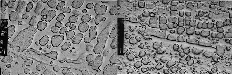
The creep strength of turbine blade alloys is strongly influenced by the morphology of the gamma prime precipitates. After heat treatment, new blades typically have either a simple structure of gamma prime precipitates of 10–50 nm in size or a duplex structure of large particles of 0.5–2 μm diameter and smaller particles of 10–50 nm size. During service, both types of structure age by an Ostwald ripening mechanism in which large particles grow at the expense of smaller particles causing a decrease in creep strength.
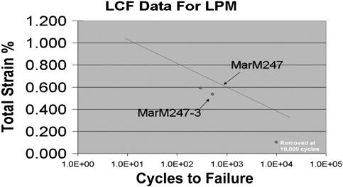
Metallographic examination of samples from the blade airfoil, after service exposure, allows the degree of gamma prime over aging to be determined (Figure 10–35). Because of the small particle size, electron microscopy must be used to image the gamma prime microstructure.
Mechanical Testing
Mechanical testing is frequently performed during metallurgical analysis of service exposed turbine blades to characterize the material properties. The results are largely influenced by the microstructural degradation mechanisms discussed above. However, mechanical test results provide quantitative measure of that degradation and, in addition, can detect some types of damage which are not microstructurally related. Typically creep rupture testing is conducted to provide an estimate of the decrease in safety margin relative to the new part and, by setting appropriate limits, can be used as a serviceability test.
Impact properties can also be of concern in instances where there is a history of FOD failures. In such cases, Charpy V-notch impact specimens are removed from the airfoil and tested at ambient or elevated temperature conditions. The results are not used predictively but are compared to a serviceability criterion arrived at by previous experience.
• The most direct and accurate way to determine remaining life in a component
• A mature O&M strategy that has demonstrated several years of success
• Requires a shutdown and overhaul
• Requires destructive testing of one or more components
• Has limited ability to extrapolate future service if different from past
Mechanical Engineering Approach
In designing hot section components mechanical engineers will target a design life. For example, one may target a 24,000 hour life in a first stage turbine blade. This would mean that the designer would limit the maximum steady and unsteady stresses to that which the material can safely endure for 24,000 hours of normal operation.
Creep damage, coating life, and low cycle thermal mechanical fatigue constraints will dictate maximum allowable stresses and temperatures in the blade. Applying these mechanical constraints on the components during the design phase requires significant modeling of the component and its material system. These models form the basis for design and are used in specifying equivalent operating hour criteria.
FEA and CFD
Finite element analysis and computational fluid dynamics are very useful modeling techniques mechanical engineers employ to design hot section components.
FEA is used to predict the operating stresses and temperature that a component will experience in service. Heat transfer and fluid dynamic boundary conditions determined by CFD are applied to the FEA model. The resulting stresses and temperatures are then entered into a material model to predict the component “design life.”
From an O&M perspective the overall system model can be used to evaluate remaining life. Even more useful, these models can be used to predict remaining life based on operating condition. For example, if the user were to operate their components at a different load than design, the life impact of this can be directly estimated with the model.
Long-Term Material Steady Behavior
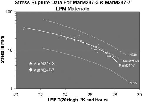
Such behavior can be characterized using Larson-Miller curves and creep rate equations combined with safety factors to account for the unknowns in the model. The Larson-Miller curve is a generally accepted method used to determine the creep life of a component given time, temperature and stress and is represented in Figure 10–36.
Material creep strain rates are used in modeling the nonlinear plasticity experienced in hot section components. For example, the long-term load shedding of a turbine root form can be estimated to predict a more representative design stress. Material creep strain rates can be represented by the classical power law for creep known as the Bailey-Norton law. The expression for uniaxial creep strain in terms of the uniaxial stress and time is represented in the following equation:
Long-Term Material Cyclic Behavior
This behavior can be classified as either high cycle or low cycle fatigue. The classification of fatigue behavior into two types characterizes the different material model damage mechanisms. Low cycle fatigue or LCF deals primarily with 1000s of cycles.
From a practical perspective, LCF is tied with engine starts or load variations which are linking with thermal and stress cycles. High cycle fatigue or HCF results from cycles much greater than 1000s and more likely in the 107 range. Practically HCF is associated with cyclic stress loading tied to the engine operating speed. For example, blades rotating past a number of vane wakes will accumulate a number of stress cycles every time the blade passes by during one revolution. Both HCF and LCF are dealt with using different material models.
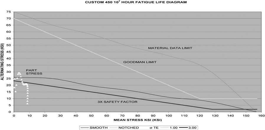
HCF can be modeled using a Goodman diagram as illustrated in Figure 10–37. A mechanical designer will design the HCF loading of the part to fall in a region on the Goodman diagram where safe operating stresses occur that ensure near infinite operating cycles.
LCF material properties are primarily deduced from laboratory testing. Most of the laboratory testing conducted to characterize the low cycle fatigue resistance of materials is carried out at constant temperature using simple waveforms with steady strain rates. By contrast a startup or trip cycle on a gas turbine hot gas path can generate quite a complex stress cycle with transient thermal loading.
To predict the fatigue life of a component exposed to the more complex cycles based on the lab test results, some simplifications must be made. The first simplification addresses the isothermal nature of most lab testing. The assumption is made that the damage accumulated during the thermal-mechanical fatigue cycles is equivalent to damage generated in isothermal testing at the peak temperature of the thermal-mechanical fatigue cycle.
Secondly, the differences between the complex strain cycle experienced by parts and the simpler cycles used in lab testing must be addressed. Under low cycle fatigue conditions, fatigue life is a function of the strain range (the maximum strain in the cycle less the minimum strain in the cycle) and test results are most commonly presented as graphs of cyclic life to failure versus strain range.
The complicated strain cycle a component sees in service is thus characterized by the strain range, to predict low cycle fatigue life from simple lab cycles. The predicted life can then be read from the LCF curve for the material at that strain range (see Figure 10–38).
Performance Engineering Approach
The performance engineering perspective on O&M is completely different from the metallurgical or mechanical approach. A performance engineering evaluation will let one know if the component is behaving the way it did historically in terms of its thermodynamic ability. For example, one could plot gas turbine efficiency over time and track its degradation. Non-recoverable efficiency loss due to erosion, oxidation, wear, or long-term bowing is measured.
Performance engineering diagnostics analyzes the gas turbine performance to try and determine the degradation in axial compressor flow, axial compressor efficiency, turbine throat area change, and axial turbine efficiency. Data can be gathered real-time from available plant instrumentation and entered into a performance analyzer such as GTAP™. In addition to determining component degradations, GTAP™ can be used to evaluate inter-stage gas path conditions like pressure, temperature, and flow.
Under certain O&M criteria, compressor washes or component refurbishments may be implemented once performance levels drop below what is considered acceptable.
• Can be implemented inexpensively to gather the most out of data that are already being logged
• Can be used to establish maintenance schedules to improve/maintain performance
• Is largely hands free and automatic requiring no machine downtime
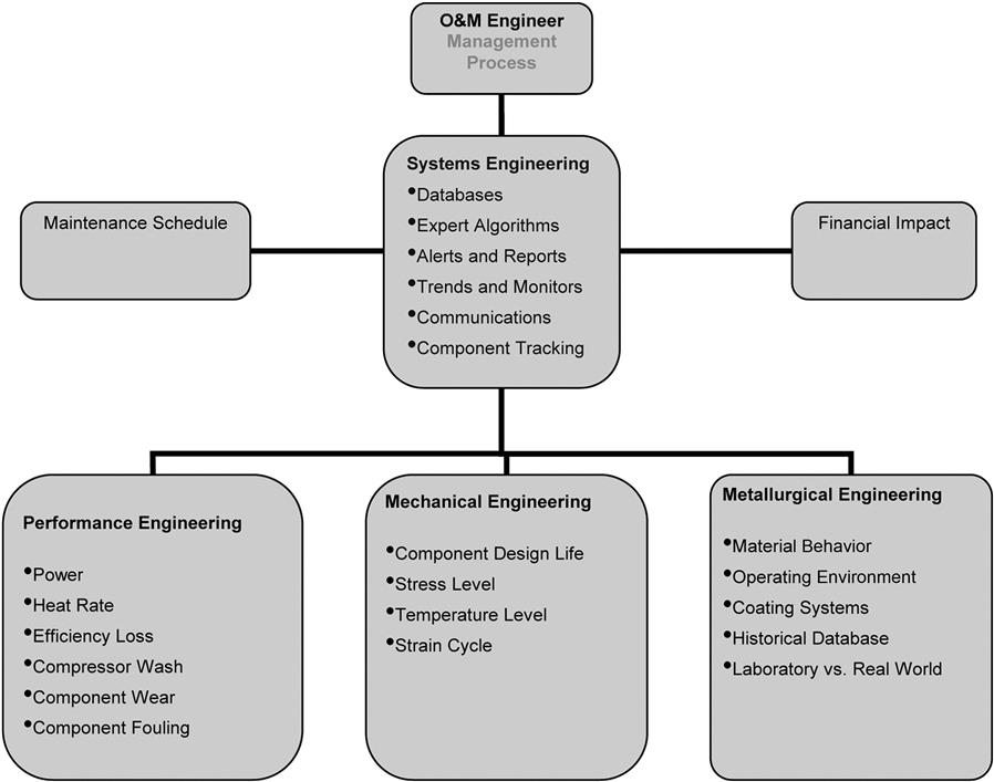
Systems Engineering Approach
As demonstrated above metallurgical, mechanical and performance engineering takes a very different approach to O&M. Although different, each discipline can be tied together in one central computing server and provided as a web service to facilitate O&M.
A component tracking and management system or CTMS has been developed to track component data at the serial number level. Its features are listed as follows:
• Designed to track hot section components in and outside of the engine.
• While out of the engine CTMS records repair shop practices implemented by serial number:
• Moment weights (if applicable)
• Rejuvenation heat treatments and history
• While in the engine CTMS records by serial number:
• OEM specified equivalent operating hours
• Metallurgical/mechanical equivalent operating hours
• Designed with a level of automation that will alarm and notify specified personnel of key indicators such as:
• Performance degradation (fouling, wash cycles etc.)
• Equivalent operating hours reaches a specified value
• Step changes in operating performance
• Hosted by a central server accessible through a secure web connection
Two potential CTMS application examples follow.
Example 1: Trailing Edge Thinning of Rotating Frame 7EA Row 2 Turbine Bucket. Metallurgical analysis revealed an engine axial inter-granular crack along the span of the trailing edge up to 7/8″ long. Metallographic investigation concluded that a creep related mechanism was responsible for the trailing edge cracking. Additionally oxidation and wear had reduced the thickness of the trailing edge to 76% of the new condition.
Mechanical analysis showed that the strain range experienced during a shutdown and a full load trip was between 0.003 and 0.004. The boundary conditions that resulted in this strain range were determined from a transient performance analysis which provided the gas path transient temperatures, pressures and flows. The LCF life was predicted to decrease significantly with reduced trailing edge thickness. So much that a 25% thickness reduction limit was set for the bucket’s trailing edge before retirement from service.
As one can see, each analysis on its own could not establish a minimum wall thickness criterion. Metallurgical analysis revealed the type of failure. Mechanical evaluation predicted strain ranges using the result of performance engineering transient gas path analysis. By combining the results of the three disciplines, a retirement criterion has been established. To implement this in practice a systems health monitoring solution would track each bucket by serial number in a database. This database would contain a remaining life quantity for each serial number. GTAP would be added to the health monitor to track gas path conditions to calculate remaining life in the part based on the mechanical engineering models described above. This remaining life number would be updated periodically in the database and when it reaches a certain number, alarms and notifications would be given by the health monitoring system to the O&M engineer.
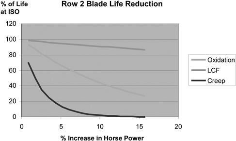
Example 2: Over-/Under-Firing a Frame 3 Gas Turbine. In some cases when the market conditions are right an operator may elect to over-fire their gas turbine to get additional capacity out of the unit during peak operation. The economic conditions in certain peak hours can be so advantageous that over-firing is very attractive and the consequential impact on maintenance needs to be estimated. Conversely there are cases where a reduced firing rate would substantially offset the maintenance cost to make it economically viable. These decisions can be made with a greater degree of confidence if a systems approach to O&M were implemented.
By archiving and tracking component remaining life in a database, the life impact of over-/under-firing can be managed and optimized. Metallurgical and performance history will dictate the life consumed thus far and forward looking mechanical analysis can predict the impact of the load changes on the remaining life. Figure 10–39 shows the impact of over-firing on the Row 2 bucket as a function of the original life and % over fire. The integral of this curve could be taken to estimate the remaining life in the bucket and then be used to optimize load vs. economics.
The next case is another example of industry working in concert with and benefiting the practical education within academia. (See Chapter 17, Training and Education.)
Case Study 3: Strategies for Integration of Advanced Gas and Steam Turbines in Power Generation Applications9
Combined cycle power plants (CCPPs) using fossil fuel generate the cleanest and most efficient form of electrical power. CCPP technologies have evolved significantly in providing better, more cost-effective products: gas turbines (GTs), steam turbines (STs), heat recovery steam generators (HRSGs), heat sinks, pollutant removal technologies, balance of plant (BOP), water treatment and fuel treatment equipment, etc. A major reason for these improvements was the introduction of G, H and now J technologies for gas turbines, in which an inseparable thermodynamic and physical link was created between the primary and secondary power generation systems by using steam instead of air, in a closed loop to perform most (or all) turbine cooling activities.
A successful and reliable operation can be achieved only when all the components listed above are harmoniously integrated. This section describes the challenges of the integration process from an engineering, procurement and construction (EPC) contractor’s perspective.
Air Permit
To get a head start on the increasingly daunting and lengthy permit process for a domestic power plant, prospective plant owners seek to obtain the services of an environmental consultant well before selecting the EPC contractor. In recent years, the permitting process in the US has become increasingly complex, requiring the involvement of several entities capable of identifying and quantifying the effect of the environmental commitments on overall project success.
A good approach is to involve the EPC contractor early. The contractor brings a larger view based on proven project designs, its database of lessons learned from other advanced equipment projects, and its startup/operating experience—a perspective that could closely reflect the owner’s continuing objectives over the life of the plant.
Improving the Permitting Process
Since the air permit is usually secured as quickly as possible, “ideal case” assumptions are sometimes made. The concern is that key factors—project design, fuel selection, type of operation, back-end equipment selection, and performance—may be determined upon submission of the air application even if all pertinent information and inputs are not available. While this tactic is useful, it is invaluable for projects having advanced GTs as prime movers.
The process definitely requires a team effort. The environmental consultant provides valuable input to the permitting strategy, giving the owner and EPC contractor broader project perspective. Both owner and contractor will ultimately need to consider issues such as constructability, initial compliance testing, long-term emission compliance, and operability and maintenance. Consequently, the process should be structured and comprehensive, encompassing the following:
• Detailed characterization of the fuels. This characterization provides the basis for sizing the gas turbine and determining the amount of supplementary firing, which ultimately define plant performance. This is followed by selecting the type and capacity of the pollution control equipment, performing steam cycle analysis, and determining heat and material balances necessary to generate pertinent emissions data for the air permit application.
• Development of a site-specific arrangement and characterization of pollution sources. If this arrangement is developed without a detailed design, the resulting layout is likely to represent a configuration that is unworkable from a design, construction, and operations point of view.
Examples of key site arrangement issues include:
1. Power block arrangement and dimensions
2. Main stack height location and base elevation
3. Stack parameters of emissions sources (stack exit diameter, velocity, height, temperature)
4. Size and orientation of cooling tower
• Definition and evaluation of supplier emissions guarantees.
The air permitting process also needs to be supported by credible emission guarantees from major equipment (e.g., GT, HRSG, auxiliary boiler) suppliers with experience and technical expertise in providing systems capable of demonstrating compliance within the proposed emission limitations. In many cases, the technical information from the suppliers is assessed using a model, which facilitates critical evaluation of the component performance by pollutant.
• Definition of the startup/shutdown processes.
Increasingly, air permits include implicit or explicit emission limitations for the startup and shutdown periods. Although these emissions are often exempt from emission compliance determinations, many state permit writers include specific compliance conditions for the startup and shutdown periods. In some cases, these conditions address warm and hot startups and the number of annual starts. In other cases, the emission limits cover all periods of operation (i.e., with no exclusions for startup or shutdown) or define specific startup/shutdown emission limits (lb/hr, lb/MMBTU). In the current market, where merchant power plants need to account for daily starts and stops, such restrictions could directly influence the profitability of the operation.
Therefore, it is essential to adequately characterize these special modes of operation and consequently determine the emission and load profiles. Limitations on startup emissions will also affect the specification of major plant equipment (i.e., GT, ST, HRSG, and auxiliary boiler).
• Assessment of the impact of monitoring uncertainty.
In the past, measurement uncertainty was not an important issue, in part because compliance limits were large enough to make such margins less significant. The measurement methodology for emissions values was sufficiently accurate that both federal and state regulators considered stack and continuous emissions monitoring to be “presumptively accurate.” However, the influence of these protective factors has disappeared. Today’s ultra-low emission limits (below 2 ppm) especially for NOx and CO, have almost eliminated any compliance margins. Since the uncertainty is a relatively larger percentage of the overall limit, actual equipment emissions must be lower than the permit limits for the plant to remain in compliance.
Gas Turbines
Equipment Selection
Before selecting the equipment from different suppliers, a thorough investigation should be conducted to ensure that the owner’s pro forma objectives for power output, heat rate/efficiency, exhaust energy, emissions, reliability, and availability are met.
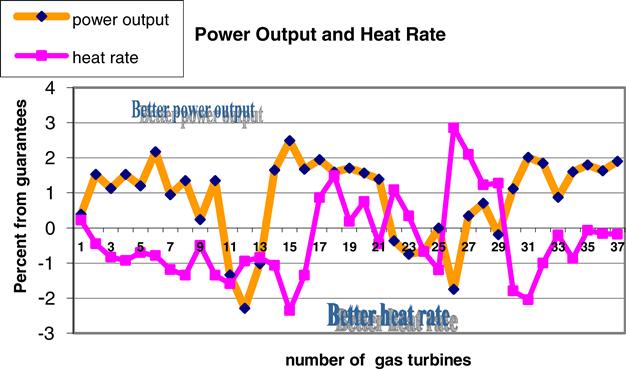
The information in the database is constantly updated with results from field tests. Figure 10–40 represents a selection of 37 GT units recently tested.
When establishing the HRSG and ST design conditions, it is a good engineering practice to allow for some variability of GT exhaust flow and temperature values. This way, the design could accommodate either shortfalls or better-than-guaranteed exhaust energy (flow and temperature). Thus, more realistic and competitive values can be predicted for the CC performance.
Our experience indicates that owners/operators are well advised to engage an experienced and bankable EPC contractor in purchase or reservation agreements for GTs or power islands. As mentioned above, such collaboration becomes crucial for projects involving advanced GTs. The EPC contractor can verify that terms and conditions essential to managing project design, construction, and commissioning are adequately covered in these agreements. An EPC contractor, with direct experience with this type of GT, can also work with the equipment supplier and the customer to ensure that the scope is complete and all interfaces are well defined. Areas where the EPC contractor can add value to an owner’s reservation agreement include:
• Establishing adequate coverage of performance test tolerances and measurement uncertainty
• Addressing the impact of GT performance offsets (between power output and exhaust energy) on HRSG and ST sizing
• Ensuring pollutant levels and units included in the plant permits and GT supplier guarantees are consistent
• Evaluating technology risk issues (e.g., use of first-of-a-kind technologies and impact of the continuous design improvement process)
• Assessing the effects of cycling operation on the plant components and their interaction
Gas Turbine Startup and Commissioning Issues
EPC contractors are responsible for starting up a CC plant and incur significant penalties if successful, timely operation is not achieved. Therefore, EPC contractors must evaluate the cost-effectiveness of approaches that facilitate rapid startup. The problem becomes even more critical for merchant power plants, where cycling and part-load operation are often required. Depending on specific completion requirements and previous experience with a particular type of advanced GT, the startup schedule must allow time for unforeseen events. Some examples of these include:
• Dual-fuel operation. The design of an advanced GT focuses on using natural gas as the primary fuel. Dual-fuel capacity with oil as an alternative fuel is an option that attracts many owners because it can produce power when natural gas is not available. Dual-fuel capability adds even more complexity to already very complicated combustion systems and controls. A difficult challenge is to achieve a switchover from one fuel type to another at a reasonably high power level. For some manufacturers, this activity took longer than expected and affected the commissioning schedule.
• Implementation of modifications in the field. Several critical advanced GT integration lessons learned are related to field modifications. On many occasions, unscheduled outages are used not only to correct a problem but also to implement a number of changes based on experience accumulated from other sites. Significant modifications incorporated include not only physical changes in the hardware but also control software. This process creates a “ripple effect” requiring additional changes in the complete plant control software and start sequences. Managing these changes is critical to maintaining schedule on advanced GT projects.
• Combustion system commissioning and tuning. To meet the strict emissions requirements, all advanced GT combustion systems operate with dry low-NOx (DLN) combustion systems. Combustion system operation from diffusion mode at low loads to full premix mode at base load takes place in several complicated steps and stages, requiring very close control of the fuel flow and exhaust temperature. The process is sensitive to ambient conditions, combustion-associated instabilities, and even manufacturing or assembly tolerances. Currently, each GT is individually adjusted to meet the performance guarantees and emissions requirements without combustion oscillations. This practice has become a standard feature of GT commissioning.
However, this activity impacts the EPC contractor. The execution schedule is extended to perform a water wash of the compressor before the tuning process and to install and remove temporary instrumentation for full-blown performance testing of the GT. Because emissions limits must be met at all ambient conditions, adjustments made in the field might modify the performance correction curves for ambient temperature.
Additional Gas Turbine Lessons Learned
Advanced GTs with DLN combustion technology may require the ability to both heat and cool fuel gas during startup. As GTs proceed to higher outputs and efficiencies, the fuel gas supply pressure requirements typically exceed 30 barg and can sometimes exceed 35 barg for can-type combustion systems.
These supply pressures often require supplemental fuel gas compression. During startup at low fuel flow rates, operation of supplemental compressors can result in significant increases in fuel gas temperature due to compression heat. However, DLN combustors typically require “cold” fuel for initial startup. As a result, a startup or pilot cooler may be required downstream of the supplemental fuel gas compressor. Later on, as the GT ramps up in load, heated fuel would be required for full pre-mix operation and the cooler would need to be isolated or bypassed.
On projects with widely varying fuel gas supply pressures, supplemental compressors can often be bypassed, even during startup. Therefore, both a dewpoint heater and a startup/pilot cooler would be required for the fuel gas supply system to meet startup fuel gas requirements under all scenarios.
Steam Turbines
In the last 10 years, STs in CC applications have evolved significantly from small 80 MW, two-pressure, non-reheat configurations to large multiple admission pressure reheat turbines with outputs reaching the 350 MW.
Significant differences exist between STs designed for CCs and those designed for conventional Rankine Cycle (RC) applications. Firstly, feedwater heaters are not normally used in the thermal design of the bottoming cycle for a CC. Secondly, because steam is admitted from several points in the HRSG, heat extraction from the GT exhaust energy is maximized. For the same high-pressure (HP) main steam flow, the CC low-pressure (LP) exhaust steam flow, when compared with the RC LP steam flow, can be up to 35 percent higher. Thirdly, CC designs use duct firing to compensate for reduced GT output at high ambient temperatures, which coincides with maximum summer demand for power. In the US, it has also become quite common to almost double the ST output by using massive amounts of supplementary firing to capitalize on peak summer demand.
Finally, competitive market pressures have pushed suppliers to offer a compact plant layout with axial steam exhaust using only two standard cylinders, reducing the cost of manufacturing and installation as well as the erection schedule. Although all ST manufacturers typically employ a modular building block system with standardized and corresponding components, during the plant design process, it is recommended to verify that the steam blade path should be modified. If an EPC contractor is the CC developer, it might use equipment from different manufacturers, thus requiring further optimization.
Another example of optimization is operation with substantial supplementary firing. Due to currently high natural gas prices, even small blade path changes can translate into operational savings. The customization of the LP steam turbine last stage path system is an additional case in which a “standard design” might not be the most suitable for the plant heat sink, especially for 2 × 1 and 3 × 1 multi-shaft CC configurations.
Another decision needed on most cogeneration projects is whether to design the ST and associated steam cycle equipment for a case in which no steam is required for the process. In this scenario, a larger LP section and an increased downstream electrical equipment (transformer, isophase bus, etc.) capacity are required. In this decision process, economic benefits of the extra power availability and operational constraints due to possible infrequent occurrences of such conditions should be carefully considered. The selection process should be transparent and capable of evaluating not only the technology risks associated with the equipment itself but also the integration risks.
Increasing the last-stage exit area is a key factor in reducing plant capital cost and minimizing exhaust losses. For cycling plants, however, more work is necessary to demonstrate that the efficiency as well as aero-mechanical behavior during part-load operation are not much worse than in the conventional design.
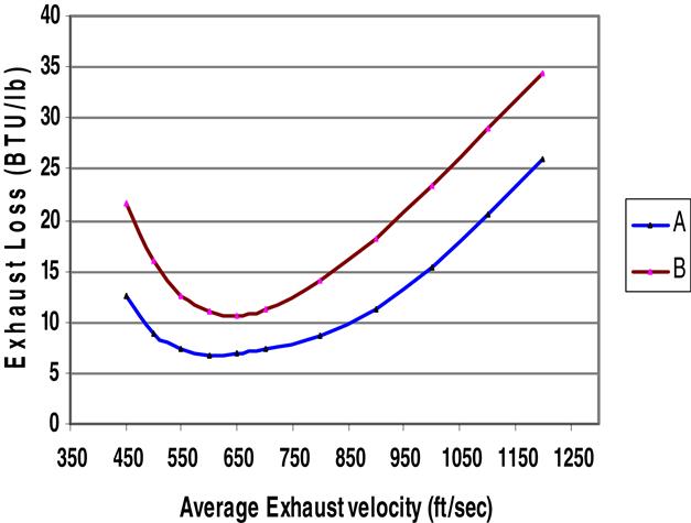
Exhaust Loss Curves
One of the important features of STs used to integrate other components and, in particular, optimize the heat sink is the exhaust loss curve. The ST thermal kit provided by the manufacturers to plant designers contains information on LP exhaust losses in the traditional form of an “exhaust losses curve.” This curve gives the specific enthalpy loss for an exhaust average steam velocity. The steam velocity value depends on the back pressure and/or steam flow. The use of this curve requires corrections for moisture content. Since the average steam exhaust velocity is a function of the volumetric flow for a given geometry, its value depends on both back pressure and steam mass flow. Figure 10–41 provides a number of exhaust loss curves for various exhaust areas. The increased exhaust loss at lower exhaust velocities (less than 550 feet per second [fps]), occurring at low part-load conditions, is due to the formation of a reverse vortex at the blade root.
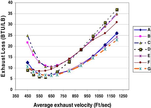
Development of new generation and often non-conventional profiles, with large variations along the blade height, has produced considerable benefits in terms of the stage’s efficiency and reduced exhaust losses. Figure 10–42 presents the exhaust curve loss for blades from two manufacturers that have almost identical exhaust and blade lengths. It can be concluded that a more advanced 3D profile design (Curve A) leads to a lower exhaust loss. Since the total exhaust loss curve also includes the contribution of the exhaust hood, its design should be aerodynamically effective.
Steam Turbine Startup and Commissioning Issues
ST startup flexibility and commissioning time play a significant role in startup of the entire CC plant. Due to higher fuel costs and increased electrical reserve margins, CC plants are dispatched as intermediate-duty units rather than base load units, as originally envisioned. Achieving the goal of a fast and reliable startup requires careful design and integration of the ST, GT, and BOP requirements. On one hand, the ST supplier should provide more flexible ST startup parameters (such as greater steam temperature mismatch and more relaxed steam purity) while maintaining reasonable constant life consumption, controlling low cycle fatigue by monitoring the maximum wall temperature differences and permissible ramp rates. On the other hand, an EPC contractor can employ the entire arsenal of auxiliary equipment available to assist in the process. Examples of such measures include means to improve the heat retention after shutdown, design of advanced water treatment systems capable of achieving steam purity more quickly, provisions for additional warmup lines, and use of an auxiliary steam boiler to reach desired condenser vacuum more rapidly.
Additional Steam Turbine Lessons Learned
Some GT/HRSG/ST combinations are better suited for rapid cycling than others. It is not possible to accurately predict CC power plant startup times from the typical startup curves for each piece of equipment. Each major equipment vendor will make assumptions about startup conditions that are most favorable for that vendor’s individual piece of equipment. These assumptions are usually different, often conflicting, and sometimes incompatible. The overall startup integration must be considered early in the project, and consistent requirements need to be provided at the bid phase for each vendor. The drive to increase ST efficiencies results in tighter clearances to reduce leakages, but these usually require longer startup times to avoid rubbing and reduce thermal stresses. Stringent steam temperature matching requirements may also be requested. These requirements vary between ST vendors and cannot always be met by every GT/HRSG combination. The GT operating at low loads has a limited capability to maintain high exhaust gas temperature. This capability varies significantly between manufacturers.
Combining a GT with limited ability to control exhaust gas temperatures at low loads with an ST that has very strict temperature requirements at startup can lead to unacceptably long startup times (greater than 8 hours) for cycling units. The HRSG may not be capable of accommodating the GT and ST requirements simultaneously without significant bypass capability. Although this scenario might seem unlikely to occur, Bechtel has witnessed this circumstance more than once, when owners procured each piece of major equipment separately, considering only performance and price with no attention to integrated startup requirements.
Cycling Considerations
The merchant plant concept implies that electric power must be supplied to the grid only when it is commercially justifiable. Such operation requirements must typically be met on very short notice. Therefore, these plants need to be started up quickly and must have flexible operating ranges. Merchant plants are normally in cycling service, which can be considered part-load operation or daily on/off duty. Heat sink considerations for a cycling plant include the following:
• Use an auxiliary boiler to sparge the condenser hotwell to prevent the condensate from subcooling
• Maintain condenser vacuum during periods of shutdown
• Use a cooling tower bypass for low-load operation
• Use pre-coat condensate treatment (condensate polisher) with air-cooled condensers, which may have large carbon steel surface areas in contact with steam and condensate
• Include provisions to control all heat sink fans from the control room. For cogeneration plants, the quality and quantity of water returned to the power plant from the process must be considered. Depending on the quality of the returned water, further deaeration and chemical treatment may be necessary. If not all the exported water is returned, additional cycle makeup will be required. An external deaerator will be required if the total cycle makeup exceeds 3 to 5 %.
Balance of Plant
Balance of Plant Equipment Selection
BOP equipment for a CCPP includes boiler feedwater pumps, condensate pumps, circulating water pumps, closed cooling water pumps, air compressors, fuel metering equipment, etc.
Proper system integration of BOP equipment also requires that interconnecting piping/support systems be optimized to the power island (GT, ST, HRSG, heat sink). Based on the arrangement of the plant and amount of BOP equipment, the engineering evaluation will start by determining the amount of circulating water, steam, air, and fuel required to operate the plant at the expected power output. The optimization of sizes, material, layout, and cost of BOP equipment and critical piping is no less important to the performance and cost of the entire plant than the power island major equipment. One of the important lessons learned was to review and continuously validate the specifications for each of the major BOP systems (main steam, feedwater, condensate, and circulating water) to rapidly respond to new requirements and incorporate the experience gained from previous projects.
Auxiliary Loads
A critical step in each project is to assess, with a high level of accuracy, the plant’s total auxiliary load at given guaranteed conditions. Auxiliary loads, representing the amount of power consumed by each piece of equipment during normal plant operation, can vary significantly due to the type of equipment and its configuration. The theoretical estimation at the beginning of the plant design must also be confirmed during performance testing. This process requires a careful engineering evaluation of the equipment in operation and the utilization factor to be applied to each piece of equipment.
A good indication of a successful design is to achieve a close match between the auxiliary load calculated and the actual values measured during the test. By conducting upfront detailed engineering to obtain actual pump performance curves and using a database of past projects’ auxiliary loads (both calculated and measured), Bechtel was able to predict with a very high degree of accuracy the auxiliary loads for the projects associated with the turbines presented in Tables 10–8 and 10–9.
TABLE 10–8
List of Projects with Bechtel Participation
| No. GTs | Type of GTs | Manufacturer | Country |
| 18 | 7FA | GE | USA, Mexico |
| 13 | 9FA | GE | UK, Turkey |
| 4 | GT26 | Alstom | UK |
| 6 | V94.3A | Siemens | Netherlands, Egypt |
| 4 | W501G | Siemens | USA |
| 9 | W501FD | Siemens Westinghouse | Brazil, Mexico, USA |
| 2 | M701F | MHI | Egypt |
| 56 Total |
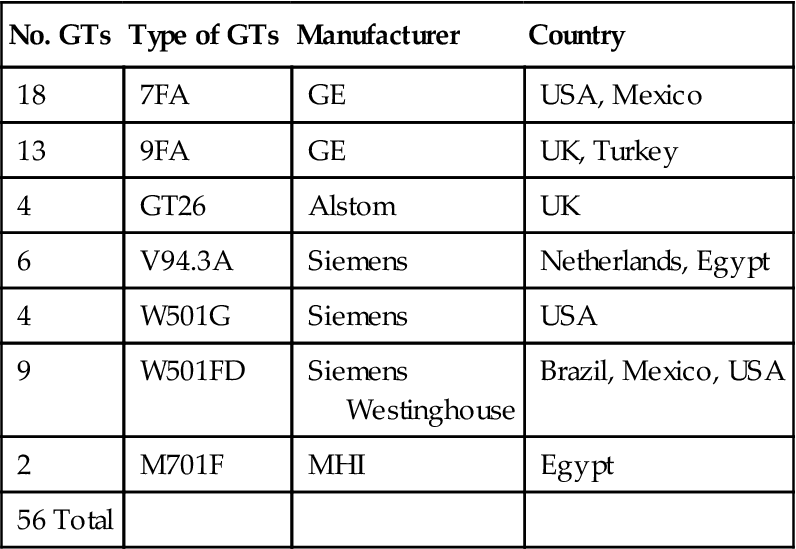
TABLE 10–9
| Supplier | No. of Units | Nominal Power (MW) | Characteristics | CC Configuration |
| Alstom | 7 | 250 | 2 × 1 | |
| Alstom | 12 | 85/155 | Unfire /duct-fired | 1 × 1 |
| Alstom | 1 | 300 | 3 × 1 | |
| GE | 1 | 300 | 2 × 1 | |
| GE | 2 | 250 | 3 × 1 | |
| GE | 1 | 150 | 1 × 1 | |
| GE | 1 | 120 | Desalinization noncondensing unit | 1 × 1 |
| GE | 3 | 200 | 2 × 1 | |
| Hitachi | 2 | 250 | 2 × 1 | |
| MHI | 2 | 100 | Cogen with large process steam | 2 × 1 |
| SWPC/MHI | 1 | 120 | 1 × 1 | |
| SWPC | 4 | 150 | 1 × 1 | |
| SWPC | 1 | 295 | 3 × 1 | |
| Toshiba | 1 | 300 | 3 × 1 | |
| Westinghouse | 1 | 230 | 2 × 1 | |
| Total | 40 |
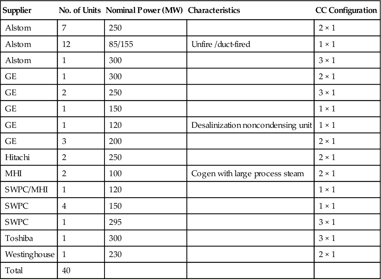
Material Selection
Tailoring material selection to the specific operating conditions of the power plant reduces the cost and ensures proper plant operation. Over the years, Bechtel has developed a material selector guide that assists the design engineer in selecting the proper material and in matching its properties to the required design parameters.
One interesting lesson learned relates to the selection of a high temperature pipe material. In the initial stage, the selected material was adequate and met the operational requirements. However, a better material, which exceeded the requirements, was found to be less expensive because the pipe diameter could be smaller and a standard schedule size could be used instead of minimum wall pipe. In another example of tailored material selection, metal pipe was replaced with high-density plastic in a low-pressure and temperature application, resulting in substantial savings.
Water Chemistry
Controlling the amount of dissolved oxygen in the condensate is critical, especially during startup. The most critical operational backstop to prevent dissolved oxygen (DO) from entering the feedwater is to avoid breaking condenser vacuum overnight (or ever). Maintaining condenser vacuum and preventing the hotwell from subcooling dramatically decreases the morning startup time and almost eliminates the huge swings in chemistry associated with cold startup. Following are lessons learned on how to minimize corrosion potential due to DO:
• Use an auxiliary boiler. For units that shut down completely at night, an auxiliary source of steam is used to maintain steam to the ST seals, thereby sustaining condenser vacuum. This auxiliary steam source is also used to sparge the condenser hotwell to prevent the condensate from subcooling and picking up DO. Additionally, the condenser sparging system is used during part-load conditions to prevent subcooling of the hotwell. The auxiliary steam source also minimizes the amount of makeup demineralized water required to support operation of the sky valves.
• Design the condenser vacuum system to utilize LP motive steam to power the steam jet air ejectors (SJAEs). If using vacuum pumps, verify that the vacuum pump cooling water supply is cold enough to stay ahead of flashing due to low vacuum conditions. A hybrid system can also be used (an arrangement where vacuum pumps take suction from SJAEs).
• Consider putting the ST gland steam condenser on the closed cooling water loop. Doing this will eliminate the need to operate the large condensate pumps during shutdown.
• Always maintain a positive pressure in the HRSG drums during shutdown. This is accomplished by closing the stack damper and all outlet valves to the HRSG after the GT is secured. At least approximately 8 to 16 hours are needed to cool the HP drum to saturated conditions of 400 to 500°F. After the boiler has cooled to within the range of the auxiliary steam source pressure, open the HP evaporator spargers and keep the drum as close as possible to drum soak conditions. This would constitute a warm start of the HRSG with no ramp-up restrictions. The heat migration from the HP section to the IP and LP sections of the boiler will tend to keep those drums at significant pressure. The LP drum must be vented throughout the night to prevent overpressurization.
If the HRSG is taken off line for maintenance under cold conditions, apply and monitor a nitrogen blanket above all water spaces and follow the manufacturer’s recommendations for chemical dosing of the drums. As the steam space pressure decreases, align the nitrogen system to push and replace the steam, which will minimize air in-leakage.
Case Study 4: A Study on the Life Cycle Impact of Steam Injection10
It is commonly believed that steam injection into a gas stream will cause an increase in heat transfer coefficient due to increase of the heat conductivity and specific heat. The criterion that sets the maximum recommended maintenance interval in industrial heavy-duty applications is based on baseload continuous operation with natural gas and no steam or water injection. For operation that differs from the baseline, maintenance factors are established that determine the increased frequency of maintenance required. Water or steam injection is one of the key factors in determining the maintenance interval requirement.
The impact of steam injection on the hot section component life of an aero-derivative LM6000PC gas turbine has been studied. Specifically, HP turbine stage 1 blade was selected as the most representative hot section component in relation to expected change in component temperature, degradation rate and serviceable life produced by the introduction and variation of the amount of steam injection.
Liburdi Turbine Services were engaged by Mighty River Power Limited of New Zealand to assess the estimated impact of increased steam injection on the LM6000PC life cycle; this section is based on that work.
Background
The industrial LM6000 gas turbine is derived from the General Electric CF6-80C2 high bypass turbofan aircraft engine. The twin spool LM6000 consists of a five-stage LP compressor, a 14-stage HP compressor, a two-stage, air-cooled HP turbine, and a five-stage LP turbine. The LM6000 does not have an aerodynamically coupled power turbine. A drive flange is available on both LP compressor and LP turbine, offering the option of either cold end or hot end drive. The LM6000PC uprated from the previous “PA/PB” model was developed in 1995. The first production unit was built in 1997. The “PC” model incorporates efficiency improvements in the LP compressor and a larger exit area in the LP turbine. The standard material for the HP turbine stage 1 blades is the Rene-142; a high strength nickel-based directionally solidified superalloy. Single crystal superalloy Rene-N5 is also used as the material upgrade. The overall pressure ratio for the LM6000PC is 29.5 to 1.
A review of repair history of the stage 1 blades revealed coating losses on the suction side leading edge at low times (Figure 10–43). Metallurgical analysis identified the most likely root cause as oxidation spallation of the thermal barrier coating (TBC).
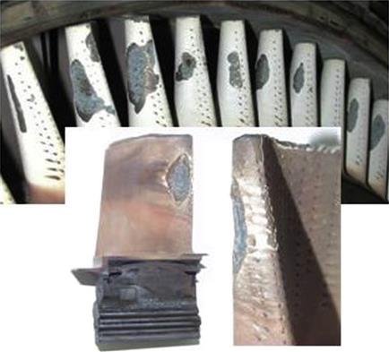
Figure 10–44 shows the blade internal cooling design. The cooling air is introduced at the blade root and exit at the blade tip. The extracted cooling airflow rate and temperature were outputted from the engine aero-thermal program. Heat transfer correlation for fully developed turbulent internal flow was used to calculate the internal heat transfer coefficients. The internal heat transfer coefficients were found to increase with increased steam injections (Figure 10–45). This can be explained by the fact that steam injection increases HP compressor discharge pressure resulting in more cooling flow extraction.
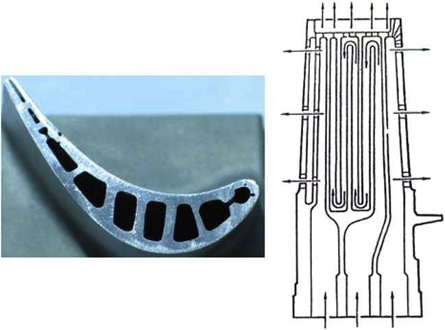
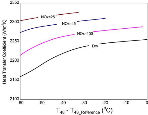
Discussion
All turbines, including aeroderivatives, have “base ratings.” In the case of aeroderivatives, when natural gas is used as the fuel and the engine is operated at the base-load power turbine inlet temperature control setting, its base rating corresponds to a hot-section repair interval of approximately 25,000 hours. In this analysis, the calculated blade metal temperature at the design base-load condition was used as the baseline reference. Figure 10–46 shows the stage 1 blade local metal temperature versus steam injection. It shows that for constant LP turbine inlet temperature control, the blade metal temperatures increase with increasing steam injections.
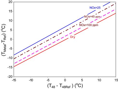
Part life impact from steam or water injection is also related to the way the engine is controlled. Most aero-derivative gas generators are controlled by the constant power turbine or LP turbine inlet temperature. Heavy-duty industrial gas turbines are in general operated with the constant firing temperature by means of a linear relationship between exhaust temperature and compressor pressure or pressure ratio. The control system on base-load application reduces firing temperature as water or steam is injected. This counters the effect of the higher heat transfer on the gas side and its impact on blade life. If the control system is designed to maintain firing temperature constant with steam injection level, this would result in additional output but the part life consumption would be accelerated. Unlike most aero-derivative gas turbines, the LM6000 is controlled by the LP turbine inlet temperature (T48) as well as the HP compressor discharge temperature (T3). With increased steam injections, engine operation would be primarily limited by the HP compressor discharge temperature. In this case, fuel flow (firing temperature) would be regulated by the engine control system to operate within the maximum allowable HP compressor discharge temperature and pressure limit.
Figure 10–47 shows the predicted stage 1 blade oxidation life change with steam injection. With the constant LP turbine inlet temperature, a 3.3% steam injection (25 ppm NOx) increases the hot-gas thermal conductivity by 3.5%. This would cause a 6.2% increase in the gas-side heat transfer coefficients. It was found that the internal cooling-side heat transfer coefficient was also increased by 3.4%. The increased heat transfer led to an average 6.6°C (12°F) increase in the local metal temperature resulting an approximate 20% reduction in the part life.
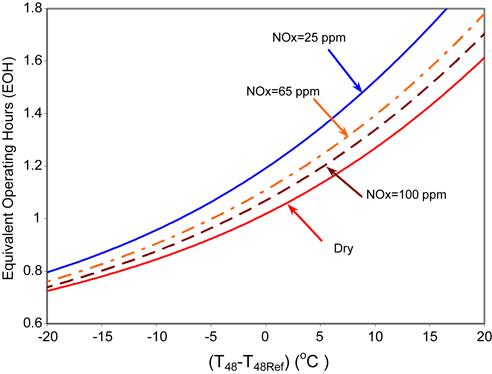
The predicted life impact of steam injection in general agrees with the reference (Figure 10–48). In an example given by the GER-3620J on the industrial Frame 7EA stage 1 bucket, for constant firing temperature, a 3% steam injection (25 ppm NOx) would result in an 8°C (15°F) increase in blade metal temperature and 33% reduction in life. It should be noted that the engine control system for the heavy duty MS7001EA gas turbine is different in design from the LM6000PC. The MS7001EA is controlled at the constant firing temperature, while the LM6000PC is controlled at the constant LP turbine inlet temperature. Secondary, the lifing criteria used by the GER-3620J may or may not be the oxidation as identified for the LM6000PC stage 1 blade.
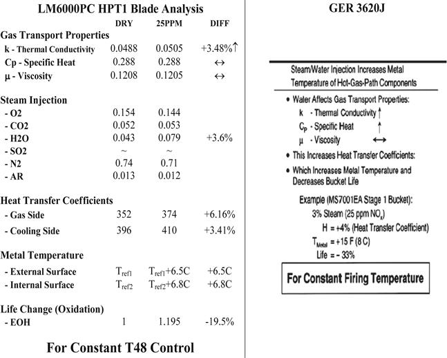
Case Study 5: Augmentation of Gas Turbine Power Output by Steam Injection11
Steam injection into the combustion chambers of gas turbines (GT) or just upstream of them (around the discharge of the compressor module) increases their power output. Additionally, the thermal efficiency can be raised, if steam is generated by exhaust heat. The types of steam injected gas turbines (STIG) are distinguished by the amount of steam that can be injected. A gas turbine is called partial STIG if the steam turbine cannot utilize the total amount of steam that could be generated by the gas turbine exhaust heat. The limit is given by the flow capacity of the turbine. If, on the other hand, the gas turbine is sized such that the entire amount of steam producible can be utilized, it is called full STIG.
Three different partial STIG cooling models were selected for analysis. Compressor surge turned out to be the strongest limit for overloading the gas turbine. At the point of maximum overload—where safe operation is still guaranteed—the steam mass flow amounts to one tenth of the nominal compressor air mass flow. At this operating point, the power output can be raised by more than 30% with a simultaneous increase in efficiency (see Figure 10–49).
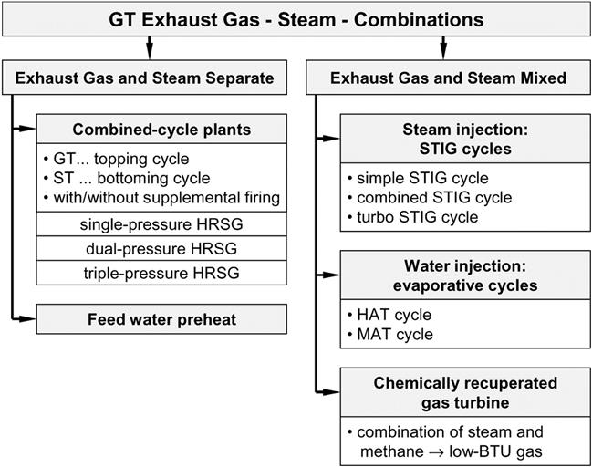
Based on the gas turbine configurations used for the partial STIGs, the preliminary designs of two full STIG cycles have been developed. However, for full STIG operation by injection of the total amount of steam producible, either the compressor or the turbines of the original gas turbine have to be modified. In this case, the steam flow exceeding that required for cooling has to be injected into the compressed air in front of the combustor. Depending on whether the compressor is scaled down or the turbines are scaled up, the power output of full STIGs is 30 to 135% higher than that of the original gas turbine. The gross thermal efficiency is about 50.5%.
Among the cycles that mix exhaust gas and steam, the steam injected gas turbine has a high specific power output and an intermediate efficiency. The two other types mentioned, the evaporative cycle and the chemically recuperated gas turbine, offer some advantages, too. Water, instead of steam, is injected into and evaporated in the humid air turbine (HAT) and the moisture air turbine (MAT). In the chemically recuperated gas turbine, heat is transferred very effectively from the exhaust gas to the low-BTU gas which is created by mixing natural gas and steam. Therefore, the heat exchanger size is optimized.
The steam to fuel ratios range from 0.5–1.5. Steam to fuel ratios of 4 to 5 are desirable (full STIG) as that would raise the power output of gas turbines significantly, however the gas turbine needs to handle the change in composition of gases and it has its limits.
| Nomenclature | ||
| [kg/s] | mass flow rate | |
| P | [MW] | power |
| TIT | [°C] | turbine inlet temperature |
| η | [–] | efficiency |
| λ | [–] | excess air ratio |
| Π | [–] | pressure ratio |
Gas Turbine with Sequential Combustion
This study used the Alstom gas turbine technology with the SEV (sequential environmental burner). Alstom models that use this technology include the GT24 and the GT26. Basically, gaseous products of combustion from one combustion chamber section have fuel injected and are reignited. See Figure 10–50. The gas turbine is a single-shaft machine with a compressor (C) and two turbines (T), each with an annular combustion chamber (CC).

A specified portion of the compressed air is taken from the compressor at an intermediate pressure, designated low pressure (LP). This amount of air, which is cooled by water, is used to cool the low-pressure section of the gas turbine. Another amount of air, smaller than that for LP cooling, is branched off at the compressor outlet and fed into the high-pressure (HP) section after having been cooled by water.
Sequential combustion has the following features: Firstly, the specific power output is higher than that of gas turbines without reheat with the same pressure ratio (TI) and the same turbine inlet temperature (TIT).
Secondly, the exhaust temperature of a gas turbine with sequential combustion is higher than that of a gas turbine without reheat. This is important for combined-cycle applications. In the case of high-pressure ratios and a given turbine inlet temperature, the turbine outlet temperature of gas turbines without reheat may become too low for efficient steam generation.
The turbine inlet temperature cannot be increased, because it is limited by the materials used and the cooling systems employed. Therefore, the only way to reach higher turbine outlet temperatures for efficient steam generation is to re-heat the gas. Both high specific GT power output and high turbine outlet temperature improve combined-cycle power plant efficiencies.
Figure 10–51 shows the thermal efficiency plotted against the specific work output of gas turbine cycles with sequential combustion.
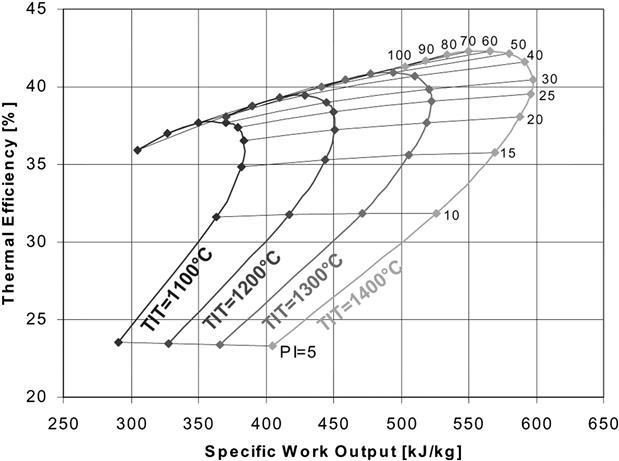
The performance map indicates that if the compressor pressure ratio is lower than 10, the thermal efficiency is decreasing with rising turbine inlet temperature. This due to the fact that the fuel input to heat up the gas to higher temperatures is higher than the work output that can be obtained from the gas during the expansion in the turbines.
On the other hand, the specific power output is rising with increasing turbine inlet temperature because the gas expands at higher temperatures.
If the compressor pressure ratio is higher than 10, the thermal efficiency and the specific power output are rising with increasing turbine inlet temperature.
The data given in Table 10–10 represent the design point of the gas turbine employed in the case study. The characteristics of several components that were used for the calculations of the off-design points with steam injection, e.g., compressor performance map, pressure losses in combustion chambers and heat exchangers, turbine performance maps, etc., are not presented here.
TABLE 10–10
Data of the Turbogroup Design Point
| ISO-Conditions | ||
| Ambient pressure | 1.013 | bar |
| Ambient temperature | 15.0 | °C |
| Relative humidity | 60.0 | % |
| Compressor | ||
| HP ratio | 30.0 | |
| LP ratio | 17.0 | |
| Compressor mass flow rate | 540.0 | kg/s |
| HP cooling air mass flow rate | 86.4 | kg/s |
| LP cooling air mass flow rate | 108.0 | kg/s |
| HP Air Cooler | ||
| Cooling temperature | 300.0 | °C |
| HP Turbine | ||
| Pressure ratio | 1.8 | |
| TIT | 1235.0 | °C |
| LP Air Cooler | ||
| Cooling temperature | 300.0 | °C |
| LP Turbine | ||
| Pressure ratio | 15.53 | |
| TIT | 1295.0 | °C |
| Mechanical efficiency | 0.995 | |
| Electrical efficiency | 0.98 | |
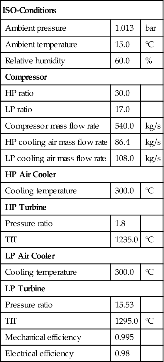
(Source: Alstom Power.)
The nominal power output of the turbogroup without steam injection is 268 MW. The thermal efficiency at generator terminals amounts to 38.5%.
Partial STIG Cycle
The partial STIG is basically a gas turbine that is overloaded by steam injection. To raise the efficiency the steam is generated by the heat of the exhaust gas.
The increase in turbine mass flow causes additional mechanical and thermal loads on the turbine blading, the rotor, the stator, and the combustion chambers of the gas turbine.
However, frequent short-term overloading does not have such a strong negative impact on the useful life of the components. No additional cooling may be required. The steam injected is used to cool the cooling air in a heat exchanger. This type of turbine cooling is called fixed indirect cooling (FIC).
If the turbine is overloaded for long periods of time, additional cooling is required to avoid a reduction in the lifetime of blades and other components.
Additional cooling can be provided by surface cooling of the increased cooling airflow by water or steam, called adjusted indirect cooling (AIC). Second, water or steam is injected into the cooling air. This cooling system is called adjusted direct cooling (ADC).
Figure 10–52 shows the partial STIG with fixed indirect cooling. Feed water is evaporated in the heat recovery steam generator (HRSG) at a temperature lower than that of the cooling air, which is 300°C.

Just a portion of the exhaust gas is required for the steam generation. Therefore, the exhaust gas stream is divided. The excess exhaust gas is passed by the heat recovery steam generator and then mixed with the other stream downstream the HRSG.
To compensate the pressure drop of the gas in the heat recovery steam generator, a suction blower is installed. It is mounted at the cold end of the steam generator because compression work as well as the thermal loading on the components of the blower are smaller at lower temperatures.
In the superheater (SH) the steam is superheated while cooling the HP cooling air. Then the superheated steam is injected into the main flow in front of the HP combustor. Since the amount of steam may not be sufficient to cool the entire amount of cooling air, the HP air cooler (ACHP) is still required. The HP cooling airflow is divided according to the amount of steam available for cooling in the superheater.
If the steam flow exceeds that needed for cooling, the surplus steam is passed by the superheater and combined again downstream with the cooling steam flow.
The partial STIG with adjusted indirect cooling, depicted in Figure 10–53, is quite similar to the partial STIG with fixed indirect cooling. The significant difference is the higher amount of cooling air.
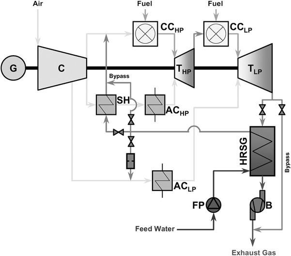
Since the LP cooling air mass flow is a fixed portion of the compressor air mass flow, an adequate portion of the steam mass flow is injected into the LP cooling system. The indirect cooling is only used in the HP cooling system.
The additional amount of HP cooling air for maintaining the cooling of the HP system is calculated by comparing the enthalpy transport capacities of air and steam. During the heat transfer from the hot gas to the cooling air the temperature drop of the hot gas and the temperature rise of the cooling air should remain constant when overloading the gas turbine. Taking these two requirements and the change of the amount of combustion air mass flow available into account, an equation can be derived to calculate the amount of cooling air necessary for a particular quantity of steam.
Another less significant difference between the fixed and the adjusted indirect cooling is the combination of the superheater and the HP air cooler. Both the series and the parallel arrangements of superheater and HP air cooler are a compromise between pressure loss and size of the heat exchangers.
The parallel arrangement is preferred when the steam injection changes frequently within the entire range of the possible steam flow rates. Both apparatus are to be designed for the maximum heat transfer capacity to cool the entire amount of cooling air.
Redundancy is built into the system’s heat exchanger capacity. In case one of them fails to perform the other can take over. This arrangement has a positive side-effect: If the airflow is distributed equally, the pressure loss in each heat exchanger amounts to just one fourth of that of the design point.
The series arrangement is better for constant steam injection into the gas turbine. Between superheater and HP air cooler the cooling air has an intermediate temperature that depends on the quantities of heat given off from the air in each of the two heat exchangers. As air temperature decreases in the superheater (a counter-current heat exchanger), its logarithmic mean temperature rises. This results in smaller heat exchanger dimensions.
The partial STIG with adjusted direct cooling is shown in Figure 10–54. This cycle is equipped with just one air cooler for the LP cooling system. HP cooling air is cooled by water or steam injection.
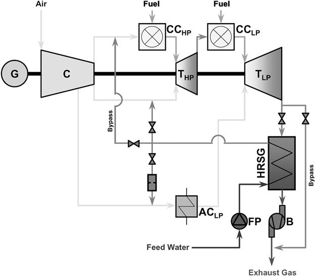
For the startup of the machine, a minimum quantity of cold water has to be injected to cool the HP cooling air. During operation, the physical state of the water injected changes depending on the amount of water fed. The state of water ranges from water to wet steam to saturated steam. If water is injected into the HP cooling system, it has to be finely dispersed to avoid erosion by water droplets.
In this cycle, the cooling air is partly replaced by steam. As for the partial STIG with adjusted indirect cooling, a similar procedure using the enthalpy transport capacity of water and steam is employed to calculate the amount of air required for cooling. At a certain steam to compressor air ratio the entire HP cooling air is replaced by steam. From now on the surplus steam is injected in front of the HP combustion chamber.
The results of the parameter study of the partial STIGs are presented in Figures 10–55 to 10–60. All parameters are plotted against the steam to compressor air ratio (steam to air ratio).
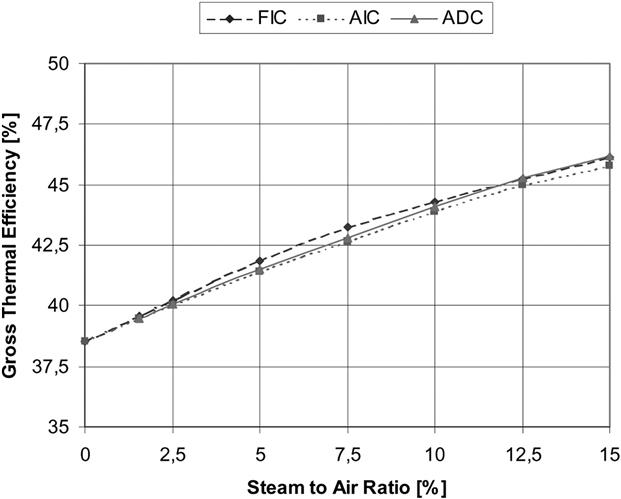
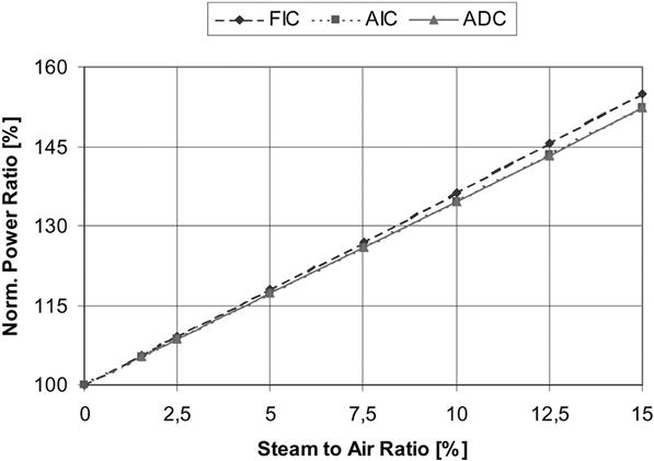
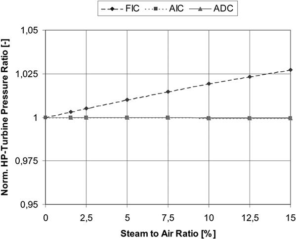
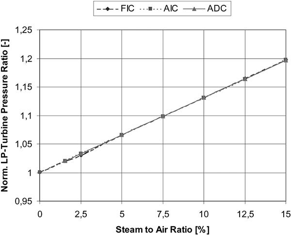
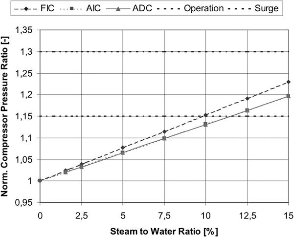
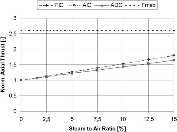
The gross thermal efficiency, depicted in Figure 10–55, includes the auxiliary equipment of the plant, e.g., feed pump, suction blower, etc. Its increase with rising steam to air ratio is produced by the partly utilized exhaust heat and the increasing pressure ratios of the turbines (see also Figures 10–56 and 10–57).
The plant with fixed indirect cooling has higher efficiencies at low steam to air ratios than the machines with adjusted indirect and direct cooling. This is because the amounts of cooling air and cooling steam are lower and the entire amount of steam is injected into the HP section of the gas turbine.
At a steam to air ratio of 7.5%, the efficiency of the cycle with fixed indirect cooling has a slight bend. This bend is caused by the amount of steam exceeding that needed to cool the HP cooling air in the superheater. The surplus steam is not superheated before injection anymore. A higher quantity of fuel is required to heat the saturated steam.
The efficiencies of the plants with adjusted cooling have a similar course. The bends are at higher steam to air ratios than that of the plant with fixed indirect cooling. Since a temperature difference between air and steam is required in the superheater, the efficiency of plants with indirect cooling is slightly lower than that of plants with direct cooling.
The increase of the power output of the gas turbine is shown in Figure 10–56. A 10% increase in turbine mass flow by water injection leads to a 30% increase in power output. This is mainly caused by the higher specific heat of steam (double that of air) and the increasing pressure ratio due to higher turbine mass flow.
The normalized12 pressure ratios of the HP turbine and the LP turbine are presented in Figures 10–57 and 10–58. To take in the increasing mass flows, the inlet pressures of the turbines and the outlet pressure of the compressor have to rise.
While the pressure ratio of the LP turbine rises linearly, that of the HP turbine remains almost constant, although the difference between inlet and outlet pressure of the HP turbine increases. The minor increase of the HP turbine pressure ratio of the cycle with fixed cooling is caused by the fact that the total amount of steam is fed into the HP turbine, while in the cycles with adjusted cooling the steam mass flow rates for HP and LP turbines are divided like that of air.
The steam injection into existing gas turbines has a strong impact on some of their components. In this section, two examples are given: The compressor surge and the axial thrust of the rotor.
Figure 10–59 shows the normalized pressure ratio, the operating limit, and the surge limit of the gas turbine. The operating limit is at the mid-point between the design point and the surge limit of the gas turbine. Since the pressure ratio of the plant with fixed cooling has a greater slope than that of the machines with adjusted cooling (the whole amount of steam is fed into the HP system of the gas turbine), the operating limit is reached earlier. In the case of adjusted cooling, the steam to air ratios are about 1.5 percentage points higher than that of the cycle with fixed cooling before reaching the operating limit.
The resultant axial thrust of the gas turbine rotor is proven not to be a serious limit for steam injection into the gas turbine as depicted in Figure 10–60. Fmax represents the maximum axial thrust of the rotor that can be absorbed by the existing thrust bearing.
As to the design of the gas turbine, the following is noted: The axial thrust, pointing in the direction of the main flow, is mainly created by the static gas pressures at the shaft shoulders. The contribution of the axial thrust caused by the flows through the compressor and the turbine blading is quite small. The slight upward bend of the curves represents the increase of thrust caused by the fact that the mass flow rate through the turbines is higher than that through the compressor.
Full STIG cycles are designed to utilize the entire amount of steam that can be produced by the exhaust gas flow. Depending on the type of cooling, there may be other limitations to the amount of steam injected, e.g., the excess air ratio in the combustion chambers.
The full STIG cycle with adjusted indirect cooling, depicted in Figure 10–61, is the simplest of the cycles investigated. Saturated steam is used to cool the cooling air, thereby becoming superheated. The steam exceeding that needed for cooling is superheated by exhaust heat. The three superheated steam flows are injected into the main flow of the gas turbine in front of the HP combustor. The excess air coefficient must be greater than 1.1 to guarantee complete combustion.
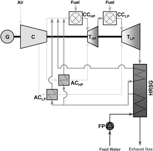
As for the partial STIG with adjusted indirect cooling, the amount of cooling air required is calculated by employing the enthalpy transport capacities of air and steam. Since a great amount of air is passing through the cooling system, the amount of steam is reached relatively early, at which the combustor airflow is just sufficient for complete combustion.
Figure 10–62 shows the full STIG cycle with adjusted direct cooling. In this cycle, no surface heat exchangers are required anymore. The air is cooled by the water or the steam injected. Since the combustion chambers and the turbines are cooled by steam instead of air, sufficient combustion air is available. The only thermodynamic limit is the exhaust heat available.
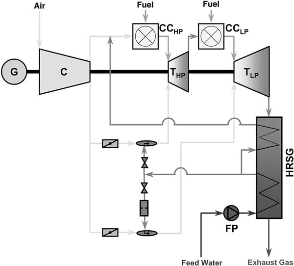
In case the steam cooling system fails to perform, two valves, controlling the HP and the LP cooling air, are opened admitting cooling air into the cooling system during a brief period of malfunction of the steam cooling. If the steam cooling cannot be restarted, the gas turbine has to be turned off slowly to avoid increased thermal loading.
In both types of full STIG operation, the turbine flow rates are greater than the compressor flow rates. Either the size of the compressor has to be reduced when the turbines are maintained, or the dimensions of the turbines have to be increased when the compressor remains unchanged. STIGs have been designed for both cases, the parameters of which are given in Table 10–11. The turbine inlet temperatures and the pressure ratios at the design point of the four STIGs are taken from the gas turbine.
TABLE 10–11
| P | [MW] | 268.06 | 345.10 | 360.83 | 508.51 | 628.54 |
| mrAir | [kg/s] | 540.00 | 360.00 | 310.00 | 540.00 | 540.00 |
| mrH2O | [kg/s] | 0.00 | 91.50 | 124.00 | 135.00 | 216.00 |
| T1 | [%] | 38.52 | 47.29 | 50.16 | 47.29 | 50.16 |
| nC | [-] | 30.00 | 30.00 | 30.00 | 30.00 | 30.00 |
| IIHP | [-] | 1.80 | 1.80 | 1.80 | 1.80 | 1.80 |
| TITHP | [°C] | 1235.00 | 1235.00 | 1235.00 | 1235.00 | 1235.00 |
| XHP | [-] | 2.40 | 1.10 | 2.08 | 1.10 | 2.08 |
| riLP | [-] | 15.53 | 15.53 | 15.53 | 15.53 | 15.53 |
| TITLP | [°C] | 1295.00 | 1295.00 | 1295.00 | 1295.00 | 1295.00 |
| XLP | [-] | 2.96 | 1.10 | 1.60 | 1.10 | 1.60 |
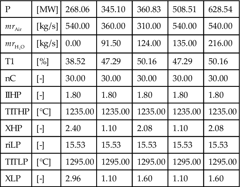
(Source: Alstom Power.)
If the HPT and the LPT are used for full STIG, then the volumetric flow rates of the turbines have to be constant to maintain the pressure ratios of the gas turbine. Since the main turbine gas flow of the full STIGs contains higher quantities of steam than that of the gas turbine produced during combustion, the turbine mass flow rates of the STIGs are lower than that of the gas turbine.
The reduction in compressor airflow and the exhaust heat utilization result in a greater power output and gross thermal efficiency of the STIGs.
For the cycles with constant compressor size, the dimensions of the turbines have to be scaled up. To get an idea of how much bigger the turbines of the two STIGs have to be made, one-dimensional flow calculations for the LP turbines were carried out. The results show that the blade height of the last turbine stage increases by about 33%. This results in a major design change which does not seam to be practical.
The smaller STIGs with downsized compressors and a slightly modified turbine design are favorable because they cause decisively lower expenses for development and they can be installed in small as well as in large power plants.
Case Study 6: Integrating Gas Turbines in Power and Cogeneration Applications13
To meet the requirements of the highly competitive combined-cycle (CC) power plant market, steam turbines (STs) have had to follow the same evolutionary path as heavy-duty gas turbines (GTs). These two types of equipment have become even more interdependent with the introduction of the new “G” and “H” GT technology classes. These new classes have created an inseparable thermodynamic and physical link between the primary and secondary power generation systems by using steam, instead of air, in a closed loop to perform most if not all of the GT cooling duty. The previous generation of GTs, the “F” class, has also undergone extensive modifications and upgrades. In addition to producing higher output, the “F” class machines are producing substantially more exhaust energy for the bottoming steam cycle.
This case describes a contractor’s experience with modern STs in all phases of a CC project: from the initial selection through construction, startup, and testing. The STs include all the major manufacturers, such as Alstom, GE, Mitsubishi, Siemens Westinghouse, and Toshiba, in several CC configurations. Several CC projects that have been completed or are in advanced stages of construction, which use the new generation of GTs and STs, are also considered.
Cycle Selection and Optimization
In the last 10 years, STs in CC applications have evolved from small 80 MW dual admission nonreheat configurations to multiple-pressure-admission reheat turbines with outputs reaching the 350 MW range. Because of this rapid evolution, many original small turbine designs have had to be modified or adjusted to compete in performance and capacity.
Differences between STs designed for CCs and conventional Rankine cycle (RC) applications are:
• Feedwater heaters are not normally used in the thermal design of the bottoming cycle for a CC; so exhaust flows are much higher.
• Steam is added to the steam path flow at several pressures from the heat recovery steam generator (HRSG) to allow the maximum amount of heat to be extracted from the GT exhaust energy. The CC low-pressure (LP) exhaust steam flow, when compared with RC LP steam flow, can be up to 35% greater than the main steam flow.
• CC designs may use supplemental or duct firing in the HRSGs to compensate for the GT’s reduced output at high ambient temperatures, which coincides with maximum (summer) power demand.
In the US, it is now common to almost double the ST output by using massive supplementary firing to capitalize on peak summer demand. Finally, competitive market pressures have pushed the ST suppliers to offer a compact plant layout with axial steam exhaust using only two standard cylinders.
This reduces manufacturing and installation costs as well as length of the construction schedule.
Although a modular building block system with standardized components and turbine parts is typically employed by all ST manufacturers, note that the steam blade path is individually designed for each application to achieve high efficiency. Even small blade path improvements can translate into large operational savings.
Figure 10–63 shows the typical thermal efficiency values for three modules (high pressure [HP], intermediate pressure [IP], and LP) for several recent projects for both unfired and fired cases. As the figure indicates, turbine cylinder efficiency in the range of 94 to 96% is not uncommon. In this analysis, the power output for the fired case, with main steam pressure at 131 bara (1900 psia), was 55 to 65% higher than the unfired case, with the main steam pressure at 69 bara (1000 psia).
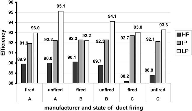
With sliding pressure operation, HP and IP module efficiency does not change significantly between the fired and unfired cases, indicating that ST operation at part load does not adversely affect the power plant heat rate. The LP module efficiency, however, does change significantly, since it is affected by the specific selection and sizing of the module and heat sink, which determine the ST operating backpressure.
Plant Configuration
One of the earliest tasks in the development phase is selection of plant configuration. Large contractors tend to maintain standardized plant designs to accommodate the OEM preferred packages. (Note that OEMs are frequently their own contractor and owner/operator.) For this contractor, they include:
A single ST for multiple GTs is less costly than a separate ST for each GT. However, multiple 1 × 1 configuration trains offer some significant advantages, as follows:
• Phased construction flexibility. Owners can add units later.
• Speed to market. As the construction duration of a 1 × 1 configuration is shorter than a 3 × 1 configuration, the first train can be commissioned, while the remaining units are still undergoing construction.
• Closer matching with dispatch demand. A site with multiple 1 × 1 trains using supplemental duct firing can more efficiently match dispatch requirements.
• Greater plant redundancy. Each unit is completely redundant.
• Optimized spare parts inventory. Identical components are used for all trains.
OEM Selection
Before selecting equipment from different suppliers, a thorough investigation is necessary to ensure that the plant owner’s requirements for power output, heat rate, startup times, reliability and availability, etc. are met.
The process includes an independent technology assessment of the equipment’s operating history and quality control for the engineering and manufacturing processes. In addition, the performance offered by the original equipment manufacturers (OEMs) for a specific project is normalized and reconciled with past performance of the same equipment in a similar configuration.
Special consideration is given to cogeneration plants where selection of cycle pressures and locations of the steam extractions is limited by the commercial availability of STs that can meet the full range of specified conditions. Most cogeneration projects require the ability to cold start the ST while the plant continues to supply full process steam requirements to the host. At the other extreme, it is also critical to determine whether to design the ST and associated steam cycle equipment for the maximum steam case when no steam is required for the process. For this instance, a larger LP section and an increased capacity for downstream electrical equipment (transformer, isophase bus, etc.) are required. Economic benefits to be realized from the availability of the extra power and operational constraints due to possibly infrequent occurrences of such conditions must be considered. Equipment selection requires the unique expertise and value-added service that only an experienced EPC contractor can provide to the customer.
Experience History
Table 10–12 lists STs from major suppliers that have been used in this contractor’s projects (96 projects using 170 GTs and more than 96 STs in CC applications).
TABLE 10–12
Steam Turbines from Major Suppliers
| Nominal Power Supplier | No. of Units | Power (MW) | Characteristics | CC Configuration |
| Alstom | 7 | 250 | 2 × 1 | |
| Alstom | 12 | 85/155 | Unfired/duct-fired | 1 × 1 |
| Alstom | 1 | 300 | 3 × 1 | |
| GE | 1 | 300 | 2 × 1 | |
| GE | 2 | 250 | 3 × 1 | |
| GE | 1 | 150 | 1 × 1 | |
| GE | 1 | 120 | Desalinization noncondensing unit | 1 × 1 |
| GE | 3 | 200 | 2 × 1 | |
| MHI | 2 | 100 | Cogen with large process steam | 2 × 1 |
| SWPC/MHI | 1 | 120 | 1 × 1 | |
| SWPC | 4 | 150 | 1 × 1 | |
| SWPC | 1 | 295 | 3 × 1 | |
| Toshiba | 1 | 300 | 3 × 1 | |
| Westinghouse | 1 | 230 | 2 × 1 | |
| Total | 38 |
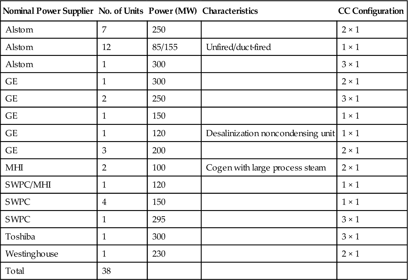
(Source: J. Zachary.)
Figure 10–64 provides a comparison of the relative efficiencies of all three configurations (1 × 1 × 1, 2 × 2 × 1, 3 × 3 × 1) as a function of the amount of process steam duty. Relative efficiency RCOGSEP is defined as the ratio between the thermal efficiency of each configuration and a reference efficiency of a conventional cycle consisting of a combined cycle producing electricity and a boiler producing process steam. In the example, for 300 MW process steam duty, a 3 × 3 × 1 configuration is slightly more efficient (RCOGSEP = 1.1323) than a 3 × (1 × 1 × 1) configuration, each exporting 100 MW (RCOGSEP = 1.1304). However, for cases where the steam duty varies, three trains, each in a 1 × 1 × 1 configuration, provide substantially greater efficiency than a 3 × 3 × 1 configuration due to the increased operating flexibility.
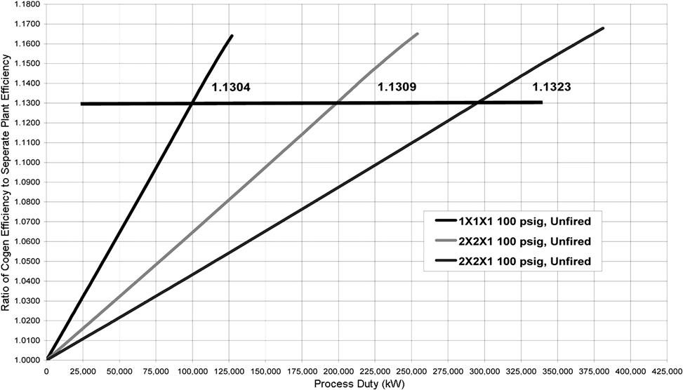
Steam Path Optimization
While ST design is a mature technology, manufacturers continue to improve the output and efficiency of their equipment through improved blade designs and superior materials. Pressures to maintain a small footprint have improved blade path parameters and offer increased stage count, reduced blade root diameter, and optimized reaction values to minimize leakages.
Evaluation of the Exhaust System: Axial, Downward, or Lateral
With the high LP flows associated with CC STs, greater emphasis is placed on the last-stage blade (LSB) dimensions and material. One major loss in the ST is the kinetic energy of the steam as it leaves the LSBs—the lower the kinetic energy that can be achieved, the higher the resulting ST efficiency. The amount of loss is proportional to the ratio of the volumetric steam flow rate through the LSBs and the annular area of the turbine exit. To decrease this loss, a larger turbine exit annulus is required. Challenges face designers, for instance aeroelastic instability, which is one of the more challenging design problems for very large LSBs. Aeroelastic instability is a vibration induced by flow, which occurs at off-design conditions in the regions of low axial steam flow and/or at high condenser pressures. The phenomenon can lead to flow separation from the airfoil, blade stall flutter, and buffeting of the blades.
Some manufacturers use titanium as the LSB material because of its high strength/weight ratio and superior corrosion resistance. However, titanium has reduced damping properties; therefore, it is generally necessary to change blade construction from freestanding to an interlocked design for increased mechanical stiffness.
The axial exhaust design has superior thermodynamic performance through lower pressure losses, greater pressure recovery in the diffuser, and simpler and less expensive construction. Because of the compact design and lower elevation, the capital cost of the ST and the turbine building can be reduced by 40% over using a double flow LP module with a bottom exhaust arrangement.
Construction
With the pursuit of compact, more efficient designs by ST manufacturers, construction tolerances and startup requirements have become more critical. As the capacity of CC STs has continued to grow, economic factors have pushed manufacturers to try to maintain the same cylinder sizes. These designs have resulted in reduced design margins and equipment that is much more sensitive to construction variables.
Fewer bearings used to support the rotor in the turbine generator set allows for shorter overall length and lower costs. Use of fewer bearings results in higher bearing loadings and increased sensitivity to vibration, which in turn leads to additional startup delays due to the added balancing time.
With the axial configuration, the location of the outboard LP bearing is an additional concern. Normally, bearing housings are easily accessible from the outside, and the housing is maintained at atmospheric pressure or at a slightly negative pressure by the vapor extractors on the lube oil reservoir. With an axial design, this bearing is in the exhaust region and is subject to condenser backpressure conditions. In some cases, a small amount of leakage across the housing flanges or inspection openings introduces oil into the cycle. Because this leakage is difficult to detect, the resulting cleanup can be extensive.
The axial exhaust design has an additional feature that is sensitive to design tolerances—the large axial loads on the turbine during startup that are transmitted to the turbine foundations. The foundation must handle this loading with minimal deflection, and the slide plates under the turbine are designed to freely allow the cylinder to grow. This large axial load, due to both differential and thermal pressure, results in varying amounts of deflections, and the variation in slide plate friction results in further variation.
Further temperature stratification of the HP and IP cylinder due to differential warming or cooling during startup or shutdown has resulted in rotor binding if not adjusted properly. The sensitivity of the ST to these conditions results in further delays in project startup.
The conversion of standard 50 Hz designs to 60 Hz conditions has also resulted in unforeseen problems. Steam turbine sets that have had many reliable operating hours in their original 50 Hz configuration experience a variety of startup delays. The most significant is high vibrations that are transmitted through the STs and generators into the piping or foundations.
Startup
The ST startup flexibility and commissioning time play a significant role in startup of the entire CC plant. Heavy penalties for failing to bring the unit on line as scheduled mandate that predicted unit startup times be achieved.
Also, due to higher fuel costs and increased electrical reserve margins, CC plants are being dispatched as intermediate-duty units rather than base load, as originally envisioned. Achieving the goal of a fast and reliable startup requires careful integration of the ST and BOP requirements. The ST supplier should provide more flexible ST startup parameters (such as greater steam temperature mismatch and more relaxed steam purity) while maintaining reasonable constant life consumption, controlling low cycle fatigue by monitoring the maximum wall temperature differences and permissible ramp rates. The EPC contractor can employ the entire arsenal of auxiliary equipment available to assist in providing the narrow preoperational and operating conditions that the modern ST requires.
Improving heat retention after shutdown, using advanced water treatment systems to achieve steam purity more quickly, providing additional lines for warm-up, and using an auxiliary steam boiler to reach desired condenser vacuum more rapidly are only a few examples of the measures that can be taken. However, many of these steps can significantly increase the overall cost of the project.
Thermal Performance
Contractually, the EPC contractor must conduct a performance test for the entire CC power plant to demonstrate to the owner that thermal performance guarantees are met. However, on many occasions, component performance testing for GT, HRSG, and ST is also performed concurrently with the CC plant test. ASME Performance Test Code, PTC 6.2, is for STs in CC applications, wherein the power output is the only guarantee. The new code demands specific correction curves to account for the interaction between the HRSG and ST and sets forth stringent requirements for instrumentation accuracy.
The outcome of ST tests conducted by this contractor (13 units, 5 OEMs) is in Figure 10–65. As can be seen, many of the units did not meet their guarantees, and additional work was required to improve their performance. OEMs may under competitive pressures offer aggressive performance guarantees.
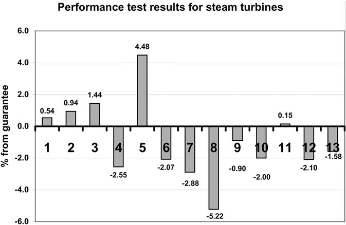
Cogeneration
Factors to be considered include:
• Supplementary firing. A popular feature of cogeneration is the use of supplementary firing (duct firing) within the HRSG. The reduction of electric power that occurs upon an increase in process steam demand can be easily overcome by duct firing in the HRSG to generate more steam. Hence, the plant is able to meet increased steam demand without reducing power output. If an additional source of unconventional off-gas fuel is available, as is often the case in chemical plants or refineries, using it for duct firing is an ideal application.
• Low-pressure turbine sizing. The design team and the owner should both agree on a decision to size the ST and associated equipment based on the “zero export steam” case. An ST passing all the steam generated will have a larger low-pressure (LP) section, larger electrical equipment (generator, transformer, etc.), and obviously a higher electrical output. Economic and thermal performance considerations must be part of the decision-making process.
• Reliability and availability. Since the export steam is used in many cases as the heat source for a chemical or industrial process, its reliability becomes a primary consideration in equipment selection and plant design. A steam outage could have a disastrous economic impact on the host facility. Table 10–13 presents the steam export reliability requirements from one Bechtel project. The reliability values vary at different steam flows and pressure ranges.
TABLE 10–13
Example of Reliability Values as a Function of Flow and Pressure
| Flow Requirements | Pressure Requirements | ||
| Flow Range (lb/hr) | Reliability (%) | Pressure Range (psia) | Time Allowable |
| 0–250,000 | 100 | 600–615 | Indefinitely |
| 575–600 | |||
| 250,000–500,000 | 99.9 | 615–6300 | 4 hours |
| 500,000–1,250,000 | 99 | Below 575 | 5 minutes |
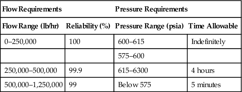
(Source: J. Zachary.)
Case Study 7: An Integrated Combined-Cycle Plant Design that Provides Fast Start Capability at Base-Load14
While efficiency is still the major driver in combined-cycle power plant design, there is an increasing need for operational flexibility along with additional operating cost reduction. Nightly and weekend shutdowns and subsequent startup capabilities should be considered during the overall evaluation of a power plant. Advancements in gas turbine technology have increased power and efficiency while decreasing emissions and life-cycle costs without sacrificing reliability.
Despite advances in gas turbine power and efficiency, when used in combined-cycle application, plant owners were traditionally forced to choose between high efficiency or operational flexibility (at the expense of efficiency). Although it has always been important to provide operational flexibility in order to enhance the value and agility of power generation assets, it has not been economical.
Gas turbines have traditionally been required to compromise their fast-loading capability to accommodate the limitations of the HRSG, steam turbine, and other components. By properly designing and integrating the plant components to allow a fast start capability while dramatically reducing startup fuel and emissions as well as water consumption, an economical solution is now available.
Changing the operational regime toward more intermediate duty significantly compromises its economics, especially when the asset is designed for base-load operation. The major challenge facing asset managers, with plants operating somewhere between intermediate and continuous-duty, is responding quickly to dispatch demands during high-profit opportunities and dispatching while revenue generation is feasible. Most combined-cycle plants recently built do not fully support these challenges.
This case will address the challenges to EPC contractors to develop improved plant concepts incorporating the latest advancements in GT technology and cycle integration that go beyond current considerations for plants designed to cycle.
This OEM’s integration of advanced GT technologies into fast-start combined-cycle plants addresses the following challenges faced by operators:
• Increased operating costs due to fuel gas consumption during non-dispatched times (i.e., startup)
• Gas turbines being operated for a prolonged period of time and more frequently in higher emission operating regimes, which may encumber emissions permitting and operational flexibility
• Lowered revenue and/or permitting issues due to increased demineralized water consumption
Advanced Gas Turbines
The Siemens F- and G-class engines share several common design attributes that are found on engines dating back to the 1960s. The evolutionary design approach and product maturation philosophy employed by Siemens PG is apparent in examining these engines. Some common features of the base design include single variable inlet guide vanes (IGVs), interlocked discs, 3-D blading, a four-stage turbine, two bearings, axial exhaust, and cold end-driven generators.
Plant Design Considerations for Fast-Start/Cycling Capability
In today’s market conditions it is assumed that combined-cycle power plants require the operational flexibility that allows them to operate anywhere between intermediate and continuous duty with the same efficiency as that of an advanced technology base-load continuous duty plant. It was found that the long established differentiation between hot, warm, and cold starts with the corresponding downtime assumptions of 8 hr (hot), 48 hr (warm) do not really reflect current operating scenarios. Therefore the fast-start plants are oriented along the following more challenging operating regime:
| Down Time | Starts per Year | |
| Overnight | 8–16 hr | 200 |
| Weekend | Up to 64 hr | 50 |
| Extended | >64 hr | 2 |
To increase the plant operational flexibility eight additional extended shutdowns were taken into consideration for component lifetime evaluation. While the plant is designed to accommodate the 260 starts per year with approximately 4000 hrs per year, it preserves its base-load operating capability. The flexibility of the design allows any combination of the number of overnight, weekend, and extended starts—up to 260 starts per year.
With regard to startup, the plant components restrict each other in terms of maximum allowable gradients/transient or necessary soaking time. This is an effect of interdependent systems and cannot be neglected. This OEM’s strategy enables:
• The gas turbine (GT) load to be ramped up in combined-cycle applications as quickly as they are in simple-cycle applications, unrestricted by downstream components including the HRSG and ST
• The ability to vary and quantify the impact of a startup on the steam turbine maintenance schedule, enabling the asset manager flexibility in setting a business strategy considering the ST and HRSG along with GT maintenance
The fast-start plant start begins with concurrent ignition of both gas turbines (1) the gas turbine generators are synchronized at (2). After an unrestricted GT ramp-up the GTs reach rated power at (3). At this point the steam turbine is also rolled off. The ST generator synchronizes at (4) while the hot reheat and low-pressure system bypass valves are closed at (5) and the ST accepts all generated steam. At this point the plant reaches approximately 97% of its rated power output.
This optimized startup scheme makes the fast-start plant’s startup approximately one-half that of its predecessor after overnight and weekend shutdowns. One of the key enablers for this improvement is Siemens’ patented Benson®15 Once-Through Steam Generator (Benson-OTSG), which can readily be applied with and without duct firing and SCR/CO-catalyst systems.
Benson Once-Through Steam Generator (OTSG)
The Benson technology has proven its capability and reliability over the past 70 years. This technology serves both sub- and supercritical designs in conventional steam power plants. Approximately 1000 Benson boilers with a cumulative steam output of more than 700,000 tons per hour have been built to date.
The authors’ company also successfully applied the Benson evaporator principle in a 390 MW combined-cycle application at Cottam Development Center, Nottinghamshire (United Kingdom). This state-of-the-art single-shaft facility owned by Powergen Plc has been in commercial operation since 1999. During this period the Benson-OTSG has shown its direct applicability for fast startup and cycling operation, even though the Cottam plant was not explicitly designed for this duty.
Based on the increased market demand for fast startup/shutdown and cycling capabilities and the successful testing and operating experience at Cottam, the fast-start plants incorporate the Benson-OTSG in their designs. Due to industry problems encountered with once-through technology of other HRSG suppliers, the design features that distinguish the Siemens Benson-OTSG from other once-through designs will be detailed/described.
The evaporator stage is characterized by two bundles of vertical tubes, which are arranged in series in the horizontal gas-path. All tubes within an evaporator bundle are connected in parallel, creating natural circulation characteristics. The low mass flux design allows the fluid mass flow to self-adjust to the heat input in each tube row, meaning tubes with higher heat absorption will see an increased fluid mass flow. This design ensures static and dynamic flow stability throughout a wide load range. In addition it results in lower pressure losses across the evaporator compared to other once-through concepts.
The Benson-OTSG is capable of handling high temperature transients during a fast startup due to the elimination of thick-walled steam drums. The HP drum, in particular, impedes fast startup of conventional HRSGs by dictating long soaking periods and slow maximum allowable temperature ramp rates. The Benson-OTSG eliminates these restrictions by replacing the drum with a small separator vessel, which also provides a more economical arrangement.
The separator performs the function of water/steam separation during startup and shutdown. At steady-state operation, including low loads, the steam flow passes through the separator, as part of the interconnecting piping toward the superheater. The steam at the evaporator outlet is slightly superheated; consequently no separation occurs.
Another common feature of once-through technology is utilized to control the main steam temperature. In contrast to a drum-type HRSG, the Benson OTSG is able to control the main steam temperature by modulating the feedwater massflow.
This enables the system to compensate the effects of changing ambient conditions or GT loads within a certain range without placing the steam attemperators in operation. Attemperators are incorporated as interstage as well as final-stage desuperheaters for the high-pressure and reheat steam systems. This arrangement ensures compliance with the steam temperature limits, dictated by the steam turbine, during plant startup.
Simply stated, the Benson-OTSG retains all the positive features offered by the traditional drum-type HRSG, including provisions for SCR, CO catalyst, duct firing, steam power augmentation, etc., while providing additional operating flexibility over drum-type HRSGs.
Steam Turbine
The steam turbine (ST) is started with power output in mind, which means that it is rapidly loaded with reduced and nearly constant steam temperatures until the bypass valves are closed with the GTs at base load. This start method eliminates steam vents to atmosphere at the HRSG, due to the incorporation of an auxiliary boiler. Since there are no HRSG- or ST-induced holds of the GT startup process, special care must be taken in handling the generated steam in order to meet the optimal steam temperature for fast loading of the ST.
The steam turbine is designed for full-arc admission without the use of a control stage. This design greatly reduces blade stresses during the startup process. The combination of full-arc admission with variable-pressure operation (which has become a standard for HRSGs in the industry) provides high efficiency, maximum operating flexibility, and minimized maintenance.
The application of high-capacity steam bypass systems for HP, IP, and LP steam is key to the operating flexibility and reliability/availability of any plant. The fast-start plants incorporate special provisions to route the HP bypassed steam into the cold-reheat of the HRSG to minimize thermal stressing of the HRSG reheater section during startup.
In order to provide further flexibility, the authors’ company’s patented Turbine Stress Controller (TSC) is supplied. The TSC consists of a stress evaluation system based on an ST startup program with an on-line life cycle counter. It calculates and controls stresses in all critical ST “thick wall” components (including the valves, HP casing and rotor body, and the IP rotor body) depending on three different ramp rates, i.e., planned, accelerated, and fast. The function of the TSC is to control the startup ramp rates in order to minimize material fatigue within the constraints of operating requirements and at the same time to calculate the cumulative fatigue of the monitored turbine parts. The TSC assigns an appropriate number of equivalent starts for each planned, accelerated, and fast start. With this knowledge of the effect of each type of start on the maintenance schedule of the steam turbine, the owner can make prudent business decisions regarding whether or not the asset should be used to satisfy transient dispatch requirements.
Steam/Water Cycle and Operational Chemistry
While the power market requirements have changed and many combined-cycle plants are being operated closer to intermediate duty with demand for fast startup/shutdown and cycling capability, asset owners still expect base-load plant efficiency levels. This is achieved not only by retaining the triple-pressure reheat steam/water cycle, but also by integration of the GT and cycle to maximize efficiency through systems such as rotor air cooling, fuel gas heating, and steam cooling of the GT transitions (in the W501G).
This cycle design has been thoroughly analyzed and as previously mentioned was first introduced at the Cottam Development Center. The Benson-OTSG is a once-through steam generator for the HP and IP sections (IP as required), while the LP section (and IP as required) retains a drum-type design. This HRSG configuration requires a combination of pH control with ammonia and oxygenated treatment. The oxygenated treatment creates and maintains a protective layer of magnetite and hematite inside the tubes.
As a further enhancement to rapidly achieve proper steam quality and to support rapid startup, the cycle incorporates a condensate polisher. The polisher provides high quality feedwater to the Benson-OTSG thus avoiding deposits in the evaporator tubes and thereby decreasing the evaporator pressure losses. The condensate is de-aerated in the condenser hotwell by vacuum, while the polisher removes the ammonia, which must then be added to the polisher effluent for proper pH adjustment.
The combined oxygen/ammonia treatment with the integrated condensate polisher of the fast-start plant has already contributed to the high reliability of Cottam Development Center and reduced the time to meet steam purity requirements to minutes.
BOP Considerations for Fast Startup/Shutdown and Cycling Operation
Noteworthy measures that are also applied in the fast-start plant are:
Benefits
Since this plant can be operated equally as well (without an efficiency impact) in fast-start, intermediate-load, or base-load modes, there is no need to optimize or design for one operating regime over another. The ability to reach dispatchable load rapidly allows the owner to participate in more revenue generation opportunities. There are other advantages that can be quantified, including:
The importance of startup emissions will be amplified as the facility tries to maximize flexibility. Without the cycle restricting the GT ramp rate, the GT reaches a low emission level rapidly producing fewer total emissions per startup. The plant thus has a significant reduction in startup emissions due to the GT reduction coupled with the benefit of any post combustion emissions controls (i.e., SCR or CO catalyst). The additional benefit, which is difficult to quantify generically, is that without these emission reductions, plant operation could be restricted or curtailed, e.g., in non-attainment areas.
Due to the lifting of cycle restrictions on the GT startup, the fast-start plants significantly reduce the fuel required for startup. This results in a savings of approximately $2.8 million a year ($23.7 M over 20 years) when the 2 × 1 W501F is operated in a nightly and weekend shutdown scenario.
Since the fast-start plant eliminates startup vents, there is also a saving in water consumption of almost 6 million gallons per year (approximately 63,000 m3) for the 2 × 1 W501F.
Case Study 8: Challenges in the Design of High Load Cycling Operation for Combined-Cycle Power Plants16
This case concerns itself with the same issue as the OEM sourced case above.
Selling electricity profitably demands dispatch responsiveness. Merchant plants are connected to the grid only when commercially justifiable. These plants need to start up quickly and have a flexible operating range at low and high capacities in a short response time. Modifications in the balance of plant (BOP) design specifications regarding sizing, materials, and operational changes affect the operational success and life of the cycling plant.
Cycling refers to operating modes that respond to changes in system load requirements. This can be as gentle as load following to part-load operation and as abrupt as daily on/off duty. Granularity in the cycling definition is achieved by dissecting specific plant operating modes usually programmed in the distributed control system (DCS). Most power island equipment providers define an approximate cooldown criteria based on the number of hours that the equipment is shut down (Table 10–14).
TABLE 10–14
| Mode | Combustion Turbine (hours) | HRSG (hours) | Steam Turbine (hours) |
| Cold start | 8 | 48 | 72 |
| Warm start | 4 | 24 | 48 |
| Hot restart | 2 | 6 | 8 |
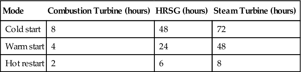
(Source: J. Zachary.)
Plant configuration was discussed in an earlier case in this chapter.
Cycle Pressure
Choosing and optimizing the cycle pressure rating is a difficult task. Relative to high mode cycling plants, where thermal stresses need to be minimized, the lower the pressure class, the better. Since the mid-1980s, the industry has moved from 1800–2000# pressure cycles and in some cases, 2400# cycles. The output benefits and heat rate benefits, along with the cost and startup time delay penalties, are shown in Table 10–15.
TABLE 10–15
Output Benefits and Heat Rate Benefits
| HP Nominal Throttle Pressure Rating | Output Increase (% MW) | Heat Rate Decrease (% BTU) | Net Cost Increase (% NPV Relative Dollars) | Cold Startup Time Increase (Minutes) | Warm Restart Time Increase (Minutes) | Hot Restart Time Increase (Minutes) |
| 1800# | Base | Base | Base | Base | Base | Base |
| 2000# | 0.1 | 0.1 | 0.5 | +15 | +10 | +5 |
| 2250# | 0.2 | 0.3 | 1.0 | +20 | +15 | +10 |
| 2400# | 0.3 | 0.4 | 1.2 | +35 | +30 | +20 |
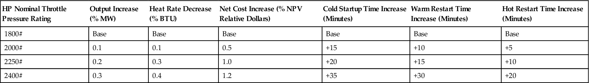
(Source: J. Zachary.)
Cost differentials do not include a schedule analysis or cost associated with schedule issues.
Combustion Turbine
The basic design of a CT makes it the most suitable power train component for high mode cycling service. OEMs may provide EOH figures for starts/stops or LCA counters or call-up inspections after a given number of starts/stops.
Although the CTs are well suited for cycling operation, there are several options that can be exercised to enhance plant cycling ability:
• CT hot air bleed: This option involves piping a compressor air bleed connection to the inlet of the CT. Extracting this relatively small amount of hot air enables CT NOx compliance down to approximately 60% of CT load. NOx compliance increases the part-load operating range. Without this option, the minimum emission limit turndown on a heavy frame CT is about 70–80%.
• Reduced inspection interval packages: Exercising this option extends the interval between hot gas path inspections and required maintenance.
• CT fast start option: This option is not offered by all CT manufacturers. Instead of a typical ramp rate of 5 MW per minute, this option enables a higher ramp rate of about 7–9 MW per minute. The fast start option enables a faster start only if the HRSG and BOP systems are designed to support a rapid CT ramp to full power. However, the increased loading rate increases the CT’s equivalent operating hours (EOH) for each fast start.
• Dehumidifying system options: Some manufacturers offer dehumidifying packages that protect the CT from internal corrosion when the unit is down. Depending on ambient conditions and the reliability of CT enclosure climate control, this option may not be required.
HRSG
By having a dedicated team follow the HRSG market, including failures and successes, continually updated commercial and technical specifications are assured. These specifications capture the following design experience.
Thermal Cycling
Thermal cycling is the premier offender in HRSG system failures. The cumulative fatigue damage from cycling cannot be reversed. Eliminate cyclic fatigue damage, and the HRSG’s life cycle will increase substantially.
From vendor data (about combating cyclic fatigue):
• Every time the HRSG is started/stopped or cycled down to part-load, thermal fatigue damage occurs. Therefore, minimizing this operating regimen is an obvious cure for this failure. Where permitted, some operators turn down their CTs to absolute minimum load through the night, so that the HRSGs can remain online and avoid a cold or warm restart in the morning. HRSG vendors claim that fatigue damage from cold starts is 20–40 times greater than from warm starts. Keep the HRSG warm overnight or over the weekend by closing the stack damper, installing insulation up to the damper, steam sparging, or running the SCR ammonia vaporizer heaters.
• The HRSG superheaters can become supercoolers during shutdown or hot/warm restarts. The condensate flow out of a hot superheater is impressive when the CT rolls back in load, resulting in the exhaust temperature cooling the finned tubes. We have been asked to assure that the DCS automatically sequences all superheater drains open if the potential for condensate collection exists when operating at reduced CT loads (especially when purging the boiler and during shutdown). Additionally, lowering the pressure/temperature of the superheated steam by following the ramp down of the CT exhaust temperature will minimize condensate formation in the lower headers upon shutdown.
• In general, all superheater drains should be generously sized and located strategically to assure all bottom headers can be completely drained. These drains are headered together under the HRSG and headered along the side of the HRSG to the blowdown or flash tank. Assure that all lines slope in the proper direction in the hot condition.
• Automatic DCS control (with manual override) should be assured for all vents and drains required for startup and shutdown.
• Hot economizers should be protected from cold water. For warm restarts, the condensate supply must match economizer temperature within 25–50°F.
Thermal Stress
The need to understand and positively control and guide thermal expansion within the boiler is paramount. The HRSG vendors offer these design features to minimize thermal stress:
• Use lower cycle pressures and higher-grade materials to keep the high-pressure (HP) drum, HP headers, and tube connections to a minimum thickness. Consider a once-through HRSG design to eliminate the HP drum altogether. The material of choice for the superheater tubes is T91.
• In the technical specification, pay for and have the HRSG vendors perform their own fatigue analyses based on American Society of Mechanical Engineers (ASME) Section VIII and BS1113. Use the results to justify where full penetration/full strength welds are required. The fatigue life of full penetration welds is at least 10 times greater than that of partial penetration welds. In many applications, the riser connection at the HP steam drum is identified as the critical area.
• Verify with the HRSG vendor that the tube offsets, harp support systems, liner panels, tube wash collection system, and all other components that will thermally expand are adequately designed to preclude thermal binding, galling, or other negative expansion effects.
• Heat treat all alloy tube bends to reduce residual stresses, avoid construction techniques that result in stress concentrations, use integral reinforced drum nozzles and full penetration nozzles, contour nozzle corners, and use blended tube to drum and other pressure boundary welds to reduce stress discontinuities.
Other Mitigation Steps
• Keep corrosion fatigue in check by assuring complete venting of economizers.
• Coat the inside of the main stack breaching and the inside portion of the stack up to the damper. Units that turn down at or near the acid or water dew point will experience wet corrosive surfaces in the back-end of the HRSG.
• Use a low-pressure (LP) economizer or condensate preheater bypass system or recirculation system to keep the temperature above the acid and water dew point past the last row of tubes in the HRSG. Consider upgrading the material on the last several rows of tubes (stainless steel is allowed for a condensate preheater/feedwater heater).
• Be aware that part-load operation of the HRSG may induce steaming in the intermediate pressure (IP) and LP economizer sections. This will accelerate local internal erosion. To prevent this, have a remote means of venting the offending economizer section directly to the drum or locate the drum level control valve downstream of the economizer section to assure that adequate pressure is always present in the economizer.
• Assure that the HRSG and connecting BOP systems are designed for the higher velocities, since part-load operation of the HRSG introduces low pressures and corresponding high specific volumes. Limit HP superheated steam and LP superheated steam and saturated steam to reasonable values. This will minimize erosion and noise at part-load conditions.
• Recognize that part-load operation (including sliding pressure) requires more separation equipment in the drum to prevent carryover to the superheater and eventually the ST. Typically ST manufacturers require a steam purity of 0.05–0.10 ppm total dissolved solids (TDS). This, unfortunately, will increase the size and thickness of the drum, which is counter to cycling requirements. In sliding pressure/part-load HRSG operation, the HP drum is typically sized for smooth operation down to 50–75% maximum continuous rating (MCR) throttle pressure.
• Size the drums to accommodate shrinking and swelling of the drum level as the load swings on the HRSG. The drum level control valve and feedwater system should be designed to keep up and successfully overcome a surge event. A relatively small surge margin on the boiler feedwater pump is usually all that is required to restore drum level during an upset condition. Additionally, assure the HP drum intermittent blowdown and drain system (including the blowdown system and the blowdown tank) are sized to control drum level upon an upset depressurization of the drum.
• Use T11 on LP riser bends to the LP drum. This increases erosion resistance for two phase and flashing flow.
• Follow the HRSG manufacturer’s lay-up procedures for nitrogen blanketing, water levels, and residual chemicals.
• Size the blowdown system generously. This will enhance the removal of corrosion byproducts upon a boiler restart and facilitate water chemistry compliance.
SCR and CO Contribution to Extended Startup Times
The presence of a CO catalyst does not contribute significantly to the startup time required for the HRSG. Since the CO catalyst is located forward in the HRSG, the CT exhaust gases typically heat up the blocks within 30 minutes.
Conversely, the selective catalytic reduction (SCR) system requires significant startup time, especially if the unit is cold. The ammonia injection grid feed piping contains a tremendous amount of metal mass and requires significant heat to obtain operating temperature. If the HRSG uses an internal gas return system (hot gas feed from downstream of the catalyst) to vaporize the ammonia, then an additional heat source is required to enable fast HRSG startup by quickly getting the SCR catalyst and piping in the required operating temperature range of 600–800°F. Several methods exist to preheat the catalyst blocks and piping:
• For SCR systems with hot gas supply through a connection downstream of the HSRG SCR, provide a hot gas recirculation system. Channel a portion of the CT exhaust gas, through a valved piping system, from the transition duct area to the inlet of the ammonia vaporizer. This system will preheat the SCR and associated piping with sufficiently hot CT gases to enable faster NOx compliance.
• Use an electric startup heater or permanent electric heater. With electric heat, this system can be activated before starting the CT.
• Heat trace the ammonia injecting feed piping and headers. Without an external source of heat, it takes at least 4 hours to heat the ammonia piping using a hot gas tap downstream of the catalyst.
Water Chemistry
Controlling the amount of dissolved oxygen in the condensate is critical, especially during startup. The most critical operational backstop to keep dissolved oxygen (DO) out of the feedwater is not to break condenser vacuum overnight (or ever). Maintaining condenser vacuum and preventing the hotwell from subcooling dramatically decreases the morning startup time and almost eliminates the huge swings in chemistry associated with cold startup. Successful strategies recommended to minimize corrosion potential due to DO include:
• Use an auxiliary boiler. For units that shut completely down at night, an auxiliary source of steam is used to maintain steam to the ST seals, thereby enabling condenser vacuum to be sustained. This auxiliary steam source is also used to sparge the condenser hotwell to prevent the condensate from subcooling and picking up DO. Additionally, the condenser sparging system is used during part-load conditions to assure the hotwell does not subcool. The auxiliary steam source also minimizes the amount of makeup demineralized water required to support operation of the sky valves.
• Design the condenser vacuum system to utilize LP motive steam to power the steam jet air ejectors (SJAEs). If using vacuum pumps, assure the vacuum pump cooling water supply is cold enough to stay ahead of flashing due to low vacuum conditions. A hybrid system can also be used (an arrangement where vacuum pumps take suction from SJAEs).
• Consider putting the ST gland steam condenser on the closed cooling water loop. This precludes having to operate the large condensate pumps during shutdown.
• Always maintain a positive pressure in the HRSG drums during shutdown. This is accomplished by closing the stack damper and all outlet valves to the HRSG after the CT is secured. It takes approximately 8–16 hours or longer to cool the HP drum to saturated conditions at 400–500°F. After the boiler has cooled to within the range of the auxiliary steam source pressure, open the HP evaporator spargers and keep the drum as close as possible to drum soak conditions. This would constitute a warm start of the HRSG with no ramp-up restrictions. The heat migration from the HP section to the IP and LP sections of the boiler will tend to keep those drums at significant pressure. The LP drum will have to be vented throughout the night to prevent overpressurization.
• If the HRSG is taken off line for maintenance under cold conditions, apply and monitor a nitrogen blanket above all water spaces and follow the manufacturer's recommendations for chemical dosing the drums. As the steam space pressure decreases, align the nitrogen system to push and replace the steam. This minimizes air in-leakage.
Steam Turbine
For one-on-one and two-on-one plants, the procedures are straightforward. For three-on-one plants, the startup procedure is involved, as is the hot/warm restart procedure. Direct bypasses, cascaded bypasses, auxiliary steam sources (if any), turbine backpressure, steam purity, sky valve operation, etc., all play an important part in steam turbine roll off.
A large East Coast combined-cycle facility was designed to accommodate the cycling requirements in Table 10–16 over the design life of the plant.
TABLE 10–16
Combined-Cycle Facility Requirements
| Startups | |
| Hot Starts | 10,000 |
| Warm Starts | 1700 |
| Cold Starts | 2000 |
| Shutdowns | |
| Trip Shutdowns of CTs | 500 |
| Fast Shutdowns of CTs | 1000 |
| Normal Shutdown of CTs | Remainder |
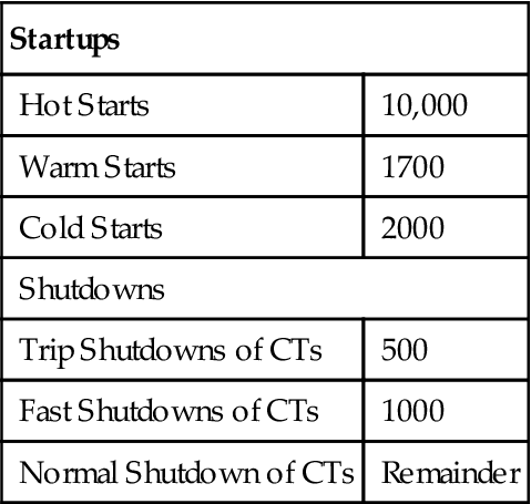
(Source: J. Zachary.)
The areas of study included crack initiation factors, centrifugal stress, creep, and material optimization. The facility has been successfully cycling daily (two-shift operation with overnight shutdowns), with weekend shutdowns, since 1992.
Some of the lessons learned from this facility and other similar installations are:
• Rapid shutdown of the ST is preferred over forced cooling (gradually reducing load before shutdown).
• Components should be chosen that are designed for minimal centrifugal stress. Using finite element analysis, have the ST supplier verify that the design of the last stage blade does not have significant stress concentrators.
• Materials optimized for creep resistance should be specified.
• Lower ST throttle pressure will allow reduced casing thickness.
• For temperature matching, especially in three-on-one installations, independent steam bypasses to the condenser are mandatory.
• Several operators use ST heater blankets to warm the casing to enable the ST to operate faster.
• To maximize cycle efficiency, the unit should be operated in sliding pressure mode, where the ST throttle valve is valve wide open (VWO). Assure the HRSG drum is sized to accommodate the higher specific volumes.
• Full-arc steam admission is commonly paired with sliding pressure boilers to improve minimum load operation and efficiency. Hybrid partial-arc admission is recommended for part-load performance and the ability to respond quickly to load changes.
• All major STs are provided standard with online stress analyzers and rotor stress indicators. Assure these are operational before turbine start.
• All extraction steam requirements (NOx injection, offsite process, SJAEs, etc.) need to be cataloged to assure the ST has minimum cooling flow and can operate as designed during part-load dispatch. Steam turbines typically require at least 15% design steam flow to remove heat from any given section.
Balance of Plant Considerations
Proper system integration assures that the facility will produce output and heat rate in accordance with specifications. System integration via the BOP equipment and interconnecting/support systems is the glue that enables the CT, HRSG, and ST to generate power reliably at all design loads and configurations.
Table 10–17 is a checklist of BOP design issues.
TABLE 10–17
| Plant Component | Design Feature | Comments |
| General | Properly characterize the plant operating modes | Specify the number of cold, warm, and hot starts; the number of shutdowns and the characterization of the shutdowns (normal, emergency, etc.). |
| Define the lowest part-load operation point of the plant | For example, 1 (50%) × 1 × 0 for a 3 × 3 × 1 plant. The lowest load point usually corresponds to the minimum load on the CT while still meeting emissions. | |
| Assure all equipment tech specs include the requirement for cycling and part-load operations | ||
| Heat sink | Part-load spargers in hotwell | This prevents the hotwell from subcooling and the subsequent O2 entrainment in the condensate. This is important to prevent system corrosion. Additionally, the spargers can be used to pre-warm the hotwell upon cold start (in conjunction with the Auxiliary Boiler option). |
| Condenser air removal system | Use vacuum pumps or alternatively use low-pressure SJAEs (100 psi) in conjunction with the Auxiliary Boiler option. | |
| Cooling tower low load operation | Use a bypass or some other option to prevent cooling tower freezing. Assure the fans can be controlled from the control room. | |
| Main steam system | Motive steam supply to the SJAEs | If an auxiliary boiler is not available to provide seal steam, consider having two seal steam sources: HP and cold reheat (CRH). The HP source is available almost immediately on startup, thus enabling the faster availability of the condenser. When conditions permit, the lower energy source (CRH) can be used to improve plant efficiency. |
| Assure pipe sizes are appropriate for the higher velocities associated with higher specific volumes during part-load cases | Follow the recommended velocity criteria for superheated for upset or emergency excursions. | |
| Cascade bypass | Cascaded bypass, as opposed to direct bypass, keeps the reheater section under positive pressure at all times (especially during startup, where a direct bypass system would put the reheater under vacuum for the initial 20 minutes until the intercepts open). Condensate can be readily blown out (not educted out), which enhances turbine water induction protection. | |
| Overboard steam line drains | Don’t try to collect the condensate from any steam drain line. Route all ST upstream steam drain lines to atmosphere. Route only the downstream ST throttle valve drains to the condenser. | |
| Feedwater system | Boiler feedwater pumps should be horizontal ring section type Variable speed drives for part-load operation of BFPs and other large rotating equipment |
Temperature gradients are OK. Pump pre-warming is not required. Promotes a cycle efficiency increase, especially with highly duct-fired units (>400 MMBTU/hr). |
| Condensate system | Assure condensate is clean and preheated prior to admission to a cold HRSG | Don’t break condenser vacuum. Hotwell sparging and side stream polishers (ACC only) should provide for clean condensate. |
| Properly size condenser air removal equipment | HEI standards are not sufficient at part-load conditions. As the condenser load decreases, backpressure decreases along with an increase of suction pressure to the vacuum removal system. Assure the system is designed to take the lower suction pressure and higher volumetric flow rate. | |
| Natural gas system | Heat trace downstream of last natural gas filter | Prevents hydrocarbons from saturating in the dead leg portion of the gas line downstream of the startup heater or cycle heater (upon CT startup). |
| Natural gas supply system to have high turndown capability | Assure gas line equipment can operate efficiently and satisfy the supplier gas spec at low loads. Gas scrubbers have only a 4–1 turndown. | |
| Circulating water system | Auxiliary circulating pump at the cooling tower | Consider using an auxiliary circulating pump to handle overnight cooling loads, so the main circulating pumps can be isolated. |
| Miscellaneous | Freeze protection | Assure adequate freeze protection is provided, since overnight or weekend shutdown may occur during sub-zero conditions. |
| Use on-line analyzers and automatic chemical feed systems Rate motors for three starts per hour |
Where appropriate, this reduces operator interface requirements. Assure electrical motors have adequate restart capability. |
(Source: J. Zachary.)
Water Treatment System Design Features
Equipment design approaches that should be evaluated to minimize water treatment problems inherent in cycling and part-load operations include: feedwater, drum water, and steam purity requirements. Ramp-up rates may be limited by the need to avoid exceeding ASME and equipment suppliers’ limits for transient drum water and steam purity.
Figure 10–66 shows a typical fluctuation of drum water quality as an 1800 psig steam generator is cycling.
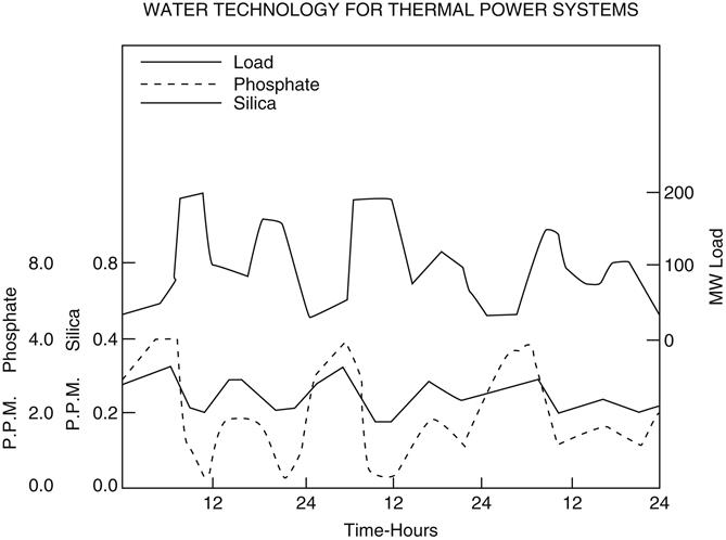
As shown in Figure 10–67, the startup data graphs for an actual combined-cycle plant, a typical warm startup should take about 2½ hours, while a cold startup takes about 3½ hours. If this time is extended due to water treatment problems, peak rate revenue opportunities may be jeopardized.
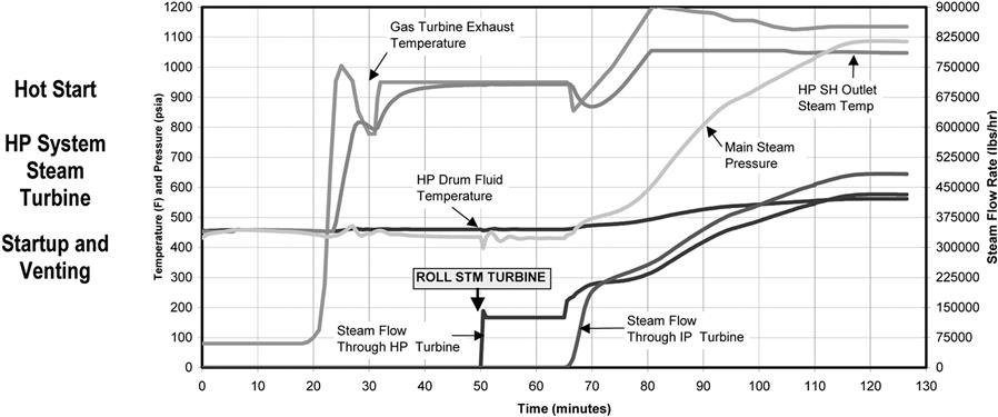
Table 10–18 shows some of the inherent causes and effects that can be caused by an inability to consistently achieve and maintain the target feedwater, drum water, and steam purity requirements.
TABLE 10–18
Feedwater, Drum Water, and Steam Purity: Inherent Causes of Problems; Short-Term and Long-Term Effects
Inherent Causes of Problems
Temperature excursions throughout the feedwater, condensate, and steam systems
Internal treatment chemical concentrations fluctuate throughout the feedwater, condensate, and steam systems
Circulation in drum not established; drum water levels fluctuate
Makeup as a proportion of total feedwater fluctuates
Short-term Effects
Startup time and responsiveness to dispatching
Extended high-rate blowdown and makeup
Longer-term Effects
Steam purity and associated problems
Accelerated corrosion of water side and steam side components
(Source: J. Zachary.)
During these transient conditions, drum water characteristics, especially pH, are difficult to control and stabilize.
As a result of these problems, passivating films can be removed; corrosion products can be displaced and transported; feedwater internal treatment chemicals can be overfed or underfed; and steam purity can be compromised.
Also, when extended high-rate blowdown and corresponding makeup rates are required to achieve and maintain the drum water and steam purity requirements, costs are incurred to provide demineralized water production and storage capacity. Energy costs can also become significant.
Erosion, corrosion, deposition, hot spots, and all other associated problems are well understood. The most immediate risk to owner-operators and contractors with startup responsibility is exceeding equipment manufacturer’s limits.
Longer term, these phenomena affect equipment serviceability and facility service life. Long-term effects can be monitored to provide “early warnings” with test heat exchangers and a comprehensive corrosion coupon program.
Operations-Based Design Criteria
Before any design features can be considered and evaluated, some basic criteria predicated on the anticipated pattern of operation should be established. Table 10–19 summarizes these operational requirements.
TABLE 10–19
Operational Design Requirements: Schedule and Availability and Ramp-Up Rate Limitations
Schedule and Availability Requirements
Overall annual availability requirement
Planned outage and/or maintenance periods
Percentage of operation at full load and part-load
Number of cold and warm starts anticipated per year
Elapsed time between shutdowns and startups
Variation in that interval; i.e., daytime-nighttime, weekend, seasonal
Ramp-up Rate Requirements and Limitations
Ramp-up time from warm status to full load
Ramp-up time from cold status to full load
HRSG and ST manufacturers’ thermal ramp-up and ramp-down rate limits
(Source: J. Zachary.)
Owner-operators, major equipment suppliers, and design engineering contractors should agree on all of these operating criteria and schedule and develop a project document that clearly defines these operational requirements.
Ideally, a present worth could be developed in terms of dollars per hour of ramp-up time either from a warm start or cold start situation.
Specific Design Features for Cycling and Part-Load Operation
Figure 10–68 shows design features that should be carefully evaluated in terms of cost-effectiveness to facilitate cycling and part-load operation.
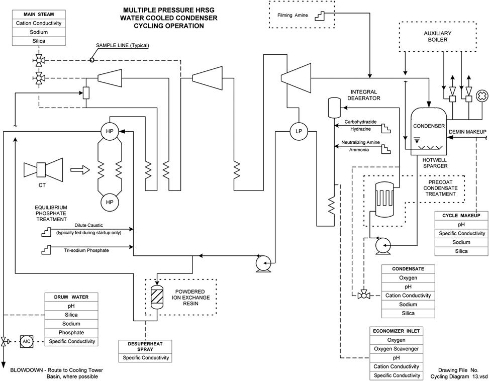
Condensate System
• Steam sparging in the condenser hotwell complements the use of auxiliary boiler and condenser vacuum pumps to degasify condensate in hotwells during short-term shutdown and to more rapidly degasify during ramp-up, ramp-down, and part-load operation.
• Use of pre-coat condensate treatment system (using either cellulose filter medium or powdered ion exchange resin) may be justified in terms of decreased startup time and fewer short- and long-term operational problems.
• Pre-coat condensate treatment systems can operate as a crud-removal filter during startup and be switched to powdered ion exchange resin after operation is stabilized. This also provides limited protection from condensate contamination due to condenser leaks.
• Pre-coat condensate treatment and use of filming amines should especially be considered for use with air-cooled condensers, which may have large carbon steel surface areas in contact with steam and condensate.
• Though more costly, the “old fashioned” stand-alone tray type de-aerator with pegging steam and reservoir is the most effective way to de-aerate feedwater. This is especially true for cycling and part-load operations. When demineralized makeup exceeds 10–15% during sustained periods of operation (such as for cogeneration export steam), the tray type de-aerator may be required to consistently achieve the oxygen concentration level typically required for thermal-mechanical de-aeration.
• Installation of a powdered ion exchange resin polisher for desuperheat water should also be evaluated to prevent introduction of contaminants from condensate directly to steam lines.
Feedwater Internal Chemical Treatment
• Owner-operator and design engineering contractor need to agree, as part of design criteria, on the feedwater internal treatment chemical approach that will be used.
• For cycling and part-load operation, use of equilibrium phosphate systems is increasing, as that appears to minimize the occurrence of phosphate hideout and the associated problems with stabilizing the drum water chemistry and the risk of hot spots or accelerated corrosion due to phosphate precipitation and/or scale accumulation.
• Dual feed capabilities should be considered, with one metering pump feeding from an organic amine tote and another feeding from an aqueous ammonia tank, with a common spare.
• An organic oxygen scavenger is needed that is relatively effective at low temperature but that will not create such a reducing atmosphere that it strips off protective oxidized films (typically magnetite). This must be a passivating type such as carbohydrazide. Provisions to continuously monitor excess oxygen scavenger as well as dissolved oxygen are also needed.
Sampling and Analysis
• Providing a comprehensive sampling and analysis system is probably the most cost-effective design provision to facilitate cycling and part-load operation.
• All samples need to be continuous with a centralized sample system and sink for all online analyzers. Sample system should include adequate sample conditioning, including filtration. Nonfiltered samples can quickly disable on-line analyzers. Provisions are also needed to take grab samples as close as possible to the origination of the sample line. Flush-out connections should also be provided at the origination of the sample lines.
• The capability to store and trend data for these parameters via a DCS system is also important.
• An empirical nomograph of expected values and control limits for the various parameters should be developed and available so that the chemical feed and blowdown can be manually controlled during ramp-up.
Makeup Demineralized Water System
• As previously discussed, the makeup demineralized water system design should be based on criteria that clearly describe the anticipated pattern of operation.
• This pattern determines the necessary demineralized water storage capacity to allow faster stabilization during startup when blowdown rate is high. It also can allow the makeup demineralized water system to be sized and divided into trains in a way that more closely matches the flow rates required.
• If reverse osmosis (RO) makeup water treatment is anticipated, provisions should be included to automatically recycle RO product water when the demineralized water or condensate storage tank is nearly full. This will minimize RO system cycling and shutdown.
• Providing variable frequency drives for RO feedwater pumps should also be evaluated to minimize hydraulic transients in element housings when systems are started up or as trains are brought in and out of service.
Heat Rejection with Water-Cooled Condenser and Cooling Tower
• Establishing and maintaining vacuum in the condenser is usually done with staged SJAEs (one set for hogging; one set for steady state operation). This is not necessarily effective over a wide range of part-load operations. Providing vacuum pumps should be evaluated.
• Using a cooling tower to receive HRSG blowdown is another method to be considered.
• Using cooling tower sidestream filtration makes circulating water quality easier to stabilize on startup and shutdown. It reduces consumption of chlorine and other internal treatment chemicals and will remove suspended solids that may be introduced from condensate dumps or HRSG blowdown.
• Copper-containing alloys should not be used because they are incompatible with amines, especially the high concentrations of amines and dissociated ammonia that are encountered during startups and shutdowns.
• Condenser tubes should be seal welded.
• Coupon testing with all types of metallurgy present in the circulating water system is important to monitor the cumulative effects of fluctuation in the circulating water chemistry.
Air-Cooled Condenser Heat Rejection
• ACCs sometimes are proposed with undersized air removal equipment, as HEI standards have been demonstrated to be undersized for some ACC applications, especially in cycling and part-load operation. Generously size ACC air removal equipment.
• As previously discussed, pre-coat condensate treatment and use of filming amines should especially be considered for use with air-cooled condensers, which may have large carbon steel surface areas in contact with steam and condensate.