Cooling and Load Bearing Systems
Abstract
Seals are found within the gas turbine’s internal air system. In summary, the seals serve to separate hot (working) gases from the cooling air required to ensure that the lubricating oil and bearings stay cool. Fully understanding their function in any one engine involves knowing the internal air system thoroughly. Some manufacturers are known for their superior cooling design. Better cooling adds cost to the overall engine in terms of both manufacture and performance efficiency. The priorities that different manufacturers set on this item are well known among seasoned gas turbine engineers who have worked with every major manufacturer’s engines. They are also well known to overhaul and repair shops that see the results of less cooling.
Keywords
Internal air system; sealing; cooling; lubrication; bearing loads; aircraft services; lubricating systems
“Learn from the mistakes of others. You’ll not live long enough to make them all yourself.”
—Old Pilot’s Saying
Seals1 are found within the gas turbine’s internal air system. In summary, the seals serve to separate hot (working) gases from the cooling air required to ensure that the lubricating oil and bearings stay cool. Fully understanding their function in any one engine involves knowing the internal air system thoroughly.
Some manufacturers are known for their superior cooling design. Better cooling adds cost to the overall engine both in terms of manufacture and performance efficiency. With manufacture, items such as laser-drilled internal passages on blades and vanes would add to the overall cost of cooling seen in the cost of manufacture. With performance, any air used for cooling is not available to be part of the working gases (which turn the turbine and develop the power). This then reduces the efficiency possible for any given air mass intake at the compressor inlet. (Note also that non-working air is also used for subsidiary systems other than cooling. In the case of aircraft engines, for instance, the air may be used for, among other uses, the cabin air-conditioning system.)
The priorities that different manufacturers set on this item are well known among seasoned gas turbine engineers who have worked with every major manufacturer’s engines. They are also well known to overhaul and repair shops that see the results of less cooling. It is the operators who wear the final results. As a shrewd design engineer once told his design team (who were anxious to squeeze every last fraction of a percent of efficiency out of a new fighter engine model): he would “rather give the pilot a better chance to get home after a mission than myself a chance to meet his angry widow” (see Chapter 14 in this book).
There is another way of keeping the engine cooler: just reduce the turbine inlet temperature. This then extends the framework of basic operation in other ways. As is detailed in Chapter 16, it can help make the use of heavier fuels possible. Residual fuel is used in some models, where customers would like to use cheap residual fuel. At the same operating temperatures that some other manufacturers use for the equivalent power in their models, even with fuel washing and pretreatment, the residual fuel would cause deposits that cake hard on the turbine blades (instead of coming off in the regular washes that use of this fuel requires). For now, let us return to the internal air system.
Internal Air System2
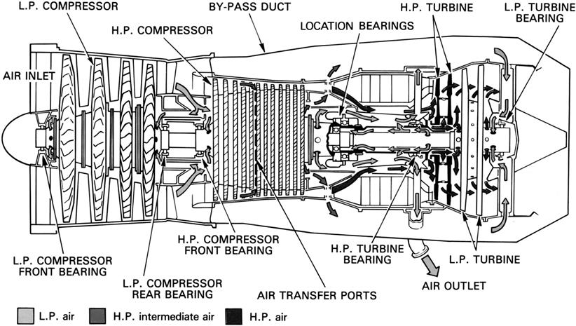
The engine internal air system is defined as those airflows that do not directly contribute to the engine thrust. The system has several important functions to perform for the safe and efficient operation of the engine. These functions include internal engine and accessory unit cooling, bearing chamber sealing, prevention of hot gas ingestion into the turbine disc cavities, control of bearing axial loads, control of turbine blade tip clearances, and engine anti-icing. The system also supplies air for the aircraft services. Up to one-fifth of the total engine core mass airflow may be used for these various functions.
An increasing amount of work is done on the air, as it progresses through the compressor, to raise its pressure and temperature. Therefore, to reduce engine performance losses, the air is taken as early as possible from the compressor commensurate with the requirement of each particular function. The cooling air is expelled overboard via a vent system or into the engine main gas stream, at the highest possible pressure, where a small performance recovery is achieved.
Cooling
An important consideration at the design stage of a gas turbine engine is the need to ensure that certain parts of the engine, and in some instances certain accessories, do not absorb heat to the extent that is detrimental to their safe operation. The principal areas that require air cooling are the combustor and turbine.
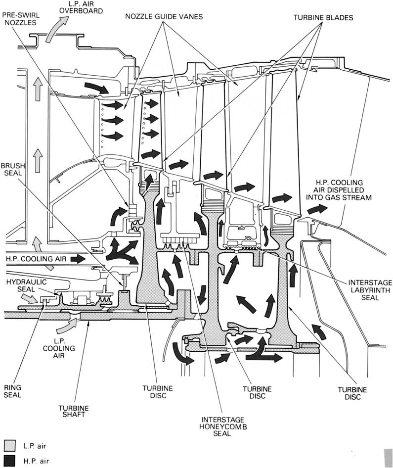
Cooling air is used to control the temperature of the compressor shafts and discs by either cooling or heating them. This ensures an even temperature distribution and therefore improves engine efficiency by controlling thermal growth and thus maintaining minimum blade tip and seal clearances. Typical cooling and sealing airflows are shown in Figure 5–1.
Turbine Cooling
High thermal efficiency is dependent upon high turbine entry temperature, which is limited by the turbine blade and nozzle guide vane materials. Continuous cooling of these components allows their environmental operating temperature to exceed the material’s melting point without affecting the blade and vane integrity. Heat conduction from the turbine blades to the turbine disc requires the discs to be cooled and thus prevent thermal fatigue and uncontrolled expansion and contraction rates.
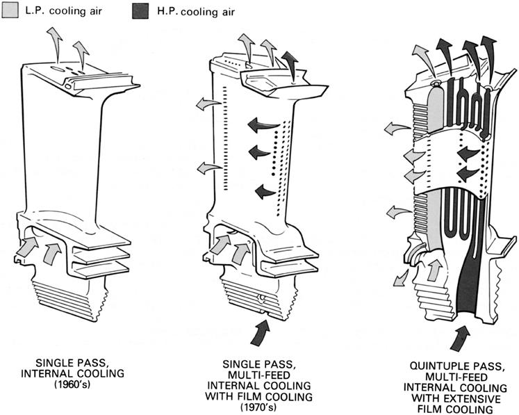
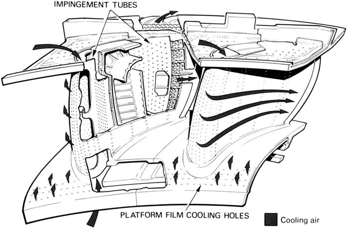
An air-cooled high-pressure nozzle guide vane and turbine blade arrangement illustrating the cooling airflow is shown in Figure 5–2. Turbine vane and turbine blade life depends not only on their form but also on the method of cooling; therefore the flow design of the internal passages is important. There have been numerous methods of turbine vane and turbine blade cooling, which have been used throughout the history of gas turbines. Generally, single pass internal (convection) cooling was of great practical benefit but development has led to multi-pass internal cooling of blades, and impingement cooling of vanes with external air film cooling of both vanes and blades; these are shown in Figures 5–3 and 5–4.

The “preswirl nozzles” (Figure 5–2) reduce the temperature and pressure of the cooling air fed to the disc for blade cooling. The nozzles also impart a substantial whirl velocity to assist efficient entry of the air into the rotating cooling passages. Cooling air for the turbine discs enters the annular spaces between the discs and flows outwards over the disc faces. Flow is controlled by interstage seals and, on completion of the cooling function, the air is expelled into the main gas stream (Figure 5–5): see the discussion on hot gas ingestion.
Bearing Chamber Cooling
Air cooling of the engine bearing chambers is not normally necessary since the lubrication system is adequate for cooling purposes. Additionally, bearing chambers are located, where possible, in the cooler regions of the engine. In instances where additional cooling is required, it is good practice to have a double skinned bearing housing with cooling air fed into the intermediate space.
Accessory Cooling
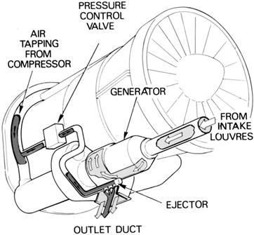
A considerable amount of heat is produced by some of the engine accessories, of which the electrical generator is an example, and these may often require their own cooling circuit. When air is used for cooling, the source may be the compressor or atmospheric air ducted from intake louvers in the engine cowlings.
When an accessory unit is cooled during flight by atmospheric air, it is usually necessary to provide an induced circuit for use during static ground running when there would be no external airflow. This is achieved by allowing compressor delivery air to pass through nozzles situated in the cooling air outlet duct of the accessory. The air velocity through the nozzles creates a low-pressure area that forms an ejector, so inducing a flow of atmospheric air through the intake louvers. To ensure that the ejector system only operates during ground running, the flow of air from the compressor is controlled by a valve. A generator cooling system with an ejector is shown in Figure 5–6.
Sealing
Seals are used to prevent oil leakage from the engine bearing chambers, to control cooling airflows, and to prevent ingress of the mainstream gas into the turbine disc cavities.
Various sealing methods are used on gas turbine engines. The choice of which method is dependent upon the surrounding temperature and pressure, wearability, heat generation, weight, space available, ease of manufacture, and ease of installation and removal. Some of the sealing methods are described in the following paragraphs. A hypothetical turbine showing the usage of these seals is shown in Figure 5–5.
Labyrinth Seals
This type of seal is widely used to retain oil in bearing chambers and as a metering device to control internal airflows. Several variations of labyrinth seal design are shown in Figure 5–7.
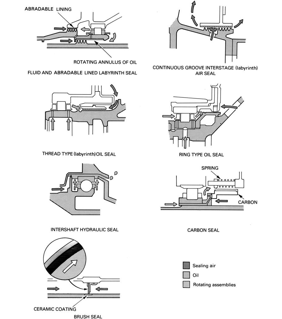
A labyrinth seal comprises a finned rotating member with a static bore that is lined with a soft abradable material or a high temperature honeycomb structure. On initial running of the engine the fins lightly rub against the lining, cutting into it to give a minimum clearance. The clearance varies throughout the flight cycle, dependent upon the thermal growth of the parts and the natural flexing of the rotating members. Across each seal fin there is a pressure drop that results in a restricted flow of sealing air from one side of the seal to the other. When this seal is used for bearing chamber sealing, it prevents oil leakage by allowing the air to flow from the outside to the inside of the chamber. This flow also induces a positive pressure, which assists the oil return system.
Seals between two rotating shafts are more likely to be subject to rubs between the fins and abradable material due to the two shafts deflecting simultaneously. This will create excessive heat, which may result in shaft failure. To prevent this, a non-heat producing seal is used where the abradable lining is replaced by a rotating annulus of oil. When the shafts deflect, the fins enter the oil and maintain the seal without generating heat (Figure 5–7).
Ring Seals
A ring seal (Figure 5–7) comprises a metal ring that is housed in a close fitting groove in the static housing. The normal running clearance between the ring and rotating shaft is smaller than that which can be obtained with the labyrinth seal. This is because the ring is allowed to move in its housing whenever the shaft comes into contact with it.
Ring seals are used for bearing chamber sealing, except in the hot areas where oil degradation due to heat would lead to ring seizure within its housing.
Hydraulic Seals
This method of sealing is often used between two rotating members to seal a bearing chamber. Unlike the labyrinth or ring seal, it does not allow a controlled flow of air to traverse across the seal.
Hydraulic seals (Figure 5–7) are formed by a seal fin immersed in an annulus of oil, which has been created by centrifugal forces. Any difference in air pressure inside and outside of the bearing chamber is compensated by a difference in oil level either side of the fin.
Carbon Seals
Carbon seals (Figure 5–7) consist of a static ring of carbon that constantly rubs against a collar on a rotating shaft. Several springs are used to maintain contact between the carbon and the collar. This type of seal relies upon a high degree of contact and does not allow oil or air leakage across it. The heat caused by friction is dissipated by the oil system.
Brush Seals
Brush seals (Figure 5–7) comprise a static ring of fine wire bristles. They are in continuous contact with a rotating shaft, rubbing against a hard ceramic coating. This type of seal has the advantage of withstanding radial rubs without increasing leakage.
Hot Gas Ingestion
It is important to prevent the ingestion of hot mainstream gas into the turbine disc cavities as this would cause overheating and result in unwanted thermal expansion and fatigue. The pressure in the turbine annulus forces the hot gas between the rotating discs and the adjacent static parts into the turbine disc rim spaces. In addition, air near the face of the rotating discs is accelerated by friction causing it to be pumped outwards. This induces a complementary inward flow of hot gas.
Prevention of hot gas ingestion is achieved by continuously supplying the required quantity of cooling and sealing air into the disc cavities to oppose the inward flow of hot gas. The flow and pressure of the cooling and sealing air is controlled by interstage seals (see Figure 5–5).
Control of Bearing Loads
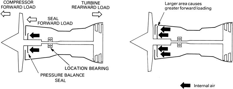
Engine shafts experience varying axial gas loads, which act in a forward direction on the compressor and in a rearward direction on the turbine. The shaft between them is therefore always under tension and the difference between the loads is carried by the location bearing, which is fixed in a static casing (Figure 5–8). The internal air pressure acts upon a fixed diameter pressure balance seal to ensure the location bearing is adequately loaded throughout the engine thrust range.
Aircraft Services (for Aircraft Engines)
To provide cabin pressurization, airframe anti-icing, and cabin heat, substantial quantities of air are bled from the compressor. It is desirable to bleed the air as early as possible from the compressor to minimize the effect on engine performance. However, during some phases of the flight cycle it may be necessary to switch the bleed source to a later compressor stage to maintain adequate pressure and temperature.
The other3 primary critical component in the cooling system is the load bearing system for the rotor, in other words, the bearings. All turbomachinery bearings depend on the lubrication system to be able to function. Further, they need an oil supply to remove dirt particles and wear debris and cool their working metal surfaces. The oil flow rate to each bearing is dictated by the orifice (supply) plate that designers place upstream of the bearing cavity. The flow varies according to the service temperature of the bearing in question. Bearings close to the hottest areas of the gas turbine get the most oil flow.
“All oil systems are not created equal.” Just as there are some OEMs that err on the side of “more cooling air at the cost of efficiency” there are OEMs that prefer “too much rather than just enough or too little cooling oil.” Just these two facts of life can affect the reception a group of operations-savvy end users give a new engine or a joint-venture design new engine (see Chapter 14).
Lubrication4
The lubrication system is required to provide lubrication and cooling for all gears, bearings, and splines. It must also be capable of collecting foreign matter, which, if left in a bearing housing or gearbox, can cause rapid failure. Additionally, the oil must protect the lubricated components that are manufactured from non-corrosion resistant materials. The oil must accomplish these tasks without significant deterioration.
Lubricating Systems
The requirements of a turbopropeller engine are somewhat different to any other type of aero-gas turbine. This is due to the additional lubrication of the heavily loaded propeller reduction gears and the need for a high-pressure oil supply to operate the propeller pitch control mechanism.
Most gas turbine engines use a self-contained recirculatory lubrication system in which the oil is distributed around the engine and returned to the oil tank by pumps. However, some engines use a system known as the total loss or expendable system in which the oil is spilled overboard after the engine has been lubricated.
There are two basic recirculatory systems, known as the “pressure relief valve” system and the “full-flow” system. The major difference between them is in the control of the oil flow to the bearings. In both systems the temperature and pressure of the oil are critical to the correct and safe running of the engine. Provision is therefore made for these parameters to be indicated in the cockpit.
Pressure Relief Valve System
In the pressure relief valve system the oil flow to the bearing chambers is controlled by limiting the pressure in the feed line to a given design value. This is accomplished by the use of a spring-loaded valve that allows oil to be directly returned from the pressure pump outlet to the oil tank or pressure pump inlet when the design value is exceeded. The valve opens at a pressure that corresponds to the idling speed of the engine, thus giving a constant feed pressure over normal engine operating speeds. However, increasing engine speed causes the bearing chamber pressure to rise sharply. This reduces the pressure difference between the bearing chamber and feed jet, thus decreasing the oil flow rate to the bearings as engine speed increases. To alleviate this problem, some pressure relief valve systems use the increasing bearing chamber pressure to augment the relief valve spring load. This maintains a constant flow rate at the higher engine speeds by increasing the pressure in the feed line as the bearing chamber pressure increases.
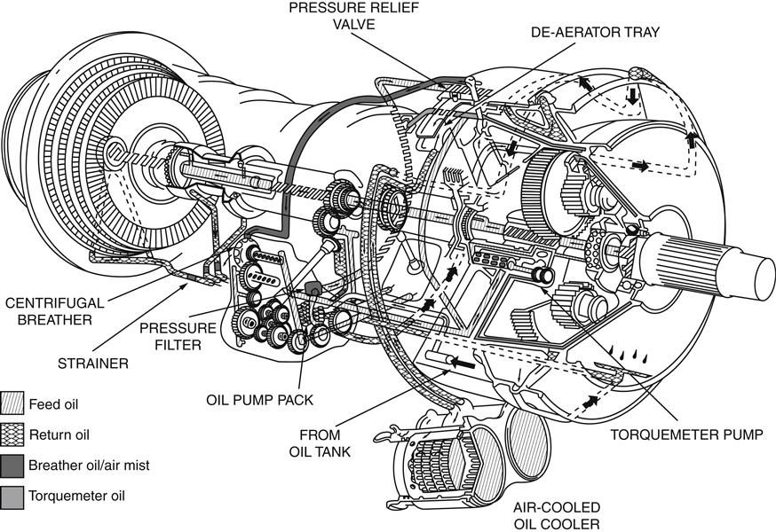
Figure 5–9 shows the pressure relief valve system for a turbopropeller engine and indicates the basic components that comprise an engine lubrication system. The oil pressure pump draws oil from the tank through a strainer, which protects the pump gears from debris that may have entered the tank. Oil is then delivered through a pressure filter to the pressure relief valve that maintains a constant oil delivery pressure to the feed jets in the bearing chambers. Some engines may have an additional relief valve (pressure limiting valve) fitted at the oil pressure pump outlet. This valve is set to open at a much higher value than the pressure relief valve to return the oil to the inlet side of the oil pressure pump in the event of the system becoming blocked. A similar valve may also be fitted across the pressure filter to prevent oil starvation of the bearing chambers should the filter become partially blocked or the oil having a high viscosity under cold starting conditions, preventing sufficient flow through the filter. Provision is also made to supply oil to the propeller pitch control system, reduction gear, and torquemeter system. Scavenge pumps return the oil to the tank via the oil cooler. On entering the tank, the oil is deaerated, ready for recirculation.
Full Flow System
Although the pressure relief valve system operates satisfactorily for engines that have a low bearing chamber pressure, which does not unduly increase with engine speed, it becomes an undesirable system for engines that have high chamber pressures. For example, if a bearing chamber has a maximum pressure of 90 lb per sq in., it would require a pressure relief valve setting of 130 lb per sq in. to produce a pressure drop of 40 lb per sq in. at the oil feed jet. This results in the need for large pumps and difficulty in matching the required oil flow at slower speeds.
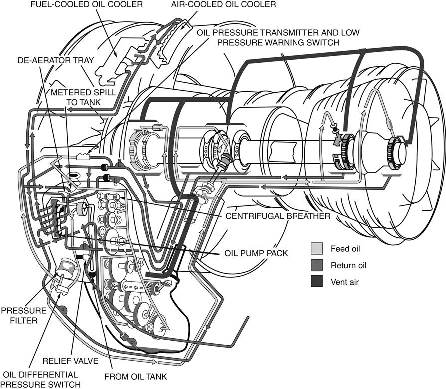
The full flow system achieves the desired oil flow rates throughout the complete engine speed range by dispensing with the pressure relief valve and allowing the pressure pump delivery pressure to supply directly the oil feed jets. Figure 5–10 shows an example of this system, which can be found on a turbofan engine. The pressure pump size is determined by the flow required at maximum engine speed. The use of this system allows smaller pressure and scavenge pumps to be used since the large volume of oil that is spilled by the pressure relief valve system at maximum engine speed is obviated.
To prevent high oil pressures from damaging filters or coolers, pressure-limiting valves are fitted to bypass these units. These valves normally only operate under cold starting conditions or in the event of a blockage. Advance warning of a blocked filter may be indicated in the cockpit by a differential pressure switch, which senses an increase in the pressure difference between the inlet and outlet of the filter.
Total Loss (Expendable) System
For engines that run for periods of short duration, such as booster and vertical lift engines, the total loss oil system is generally used. The system is simple and incurs low weight penalties because it requires no oil cooler, scavenge pump, or filters. On some engines oil is delivered in a continuous flow to the bearings by a plunger-type pump, indirectly driven from the compressor shaft; on others it is delivered by a piston-type pump operated by fuel pressure (Figure 5–11). In the latter, the oil supply is automatically selected by the high-pressure fuel shutoff valve (cock) during engine starting and is delivered as a single shot to the front and rear bearings. On some engines provision is made for a second shot to be delivered to the rear bearing only, after a predetermined period.
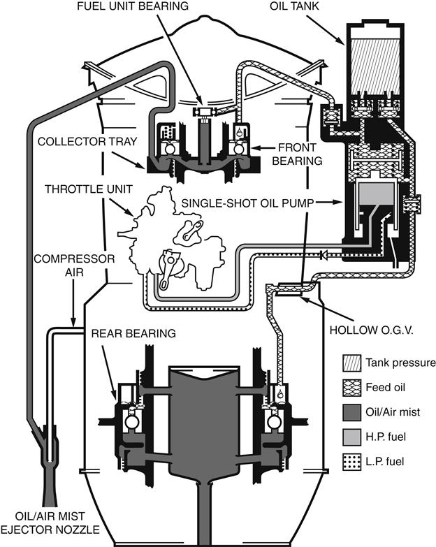
After lubricating the fuel unit and front bearings, the oil from the front bearing drains into a collector tray and is then ejected into the main gas stream through an ejector nozzle. The oil that has passed through the rear bearing drains into a reservoir at the rear of the bearing where it is retained by centrifugal force until the engine is shut down. This oil then drains overboard through a central tube in the exhaust unit inner cone.
Oil System Components
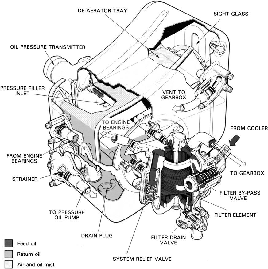
The oil tank (Figure 5–12) is usually mounted on the engine and is normally a separate unit, although it may also be an integral part of the external gearbox. It must have provision to allow the lubrication system to be drained and replenished. A sight glass or a dipstick must also be incorporated to allow the oil system contents to be checked. The filler can be either the gravity or pressure filling type; on some engines both types are fitted. Provision is also made for a continuous supply of oil to be made available in aircraft that are designed to operate during inverted flight conditions. Since air is mixed with the oil in the bearing chambers, a deaerating device is incorporated within the oil tank, which removes the air from the returning oil.
The oil pumps are vital to the efficient operation of the engine. Failure of the pumps will necessitate a rapid shutdown of the engine. For this reason, the oil pump driveshafts do not incorporate a weak shear-neck because they must continue to supply oil for as long as possible, regardless of damage.
As the feed oil is distributed to all the lubricated parts of the engine, a substantial amount of sealing air mixes with it and increases its volume. Additionally, the bearing chambers operate under differing pressures. Therefore, to prevent flooding it is usually necessary to have a scavenge pump for each chamber.
Gear type pumps are normally used in recirculatory oil systems but vane and gerotor pumps are employed in some engines. The simplicity of single-shot pumps make them ideal for engines that run for a short duration and use the total loss type of oil system.
Gear pumps (Figure 5–13) consist of a pair of intermeshing steel gears that are housed in a close-fitting aluminum casing. When the gears are rotated, oil is drawn into the pump, carried around between the teeth and casing, and delivered at the outlet.
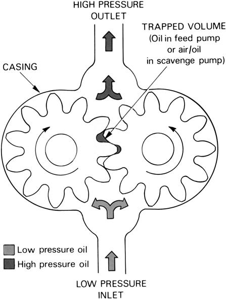
Since a small quantity of incompressible oil becomes trapped in the gear mesh, which can cause a hydraulic lock and possible pump damage, a relief slot is machined into the end faces of the casing to provide an escape route for the oil.
Gear pumps are used both as pressure (feed) pumps and scavenge (return) pumps and are incorporated within a common casing. The oil pumps pack is driven by the accessory drive system.
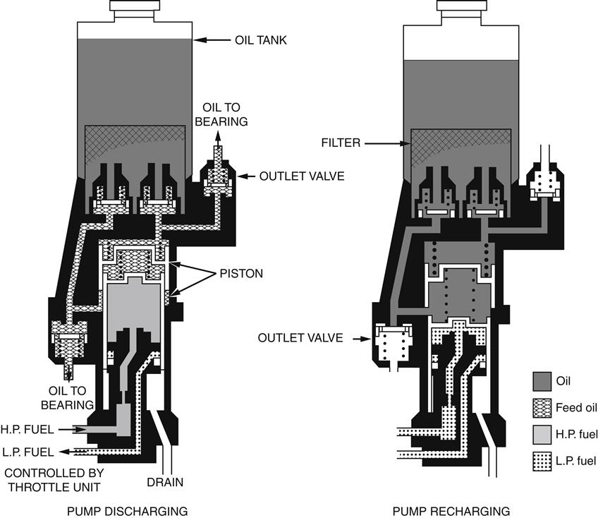
Single-shot pumps (Figure 5–14) have a quantity of oil contained within a cylinder. When the piston is forced up the cylinder bore, under the control of the throttle unit, the oil forces the outlet valves to open allowing a flow of oil to the parts required to be lubricated. When the piston reaches the top of the cylinder bore the outlet valves close due to the reduced oil pressure. Recharging of the oil pump cylinder is achieved by a spring forcing the piston to its original position. This reduces the pressure between the cylinder and the oil tank, which allows the oil replenishing valves to open until the cylinder is recharged.
The most common type of oil distribution device is a simple orifice that directs a metered amount of oil onto its target. These jet orifices are positioned as close to the target area as possible to overcome the possibility of the local turbulent environment deflecting the jet of oil. The smallest diameter of a jet orifice is 0.04 in., which allows a flow of 12 gallons per hour when operating at a pressure of 40 lb per sq in. The use of restrictors upstream can reduce the flow rate if required.
All engines transfer heat to the oil by friction, churning, and windage within a bearing chamber or gearbox. It is therefore common practice to fit an oil cooler in recirculatory oil systems. The cooling medium may be fuel or air and, in some instances, both fuel-cooled and air-cooled coolers are used.
Some engines that utilize both types of cooler may incorporate an electronic monitoring system that switches in the air-cooled cooler only when it is necessary. This maintains the ideal oil temperature and improves the overall thermal efficiency.
The fuel-cooled oil cooler (Figure 5–15) has a matrix divided into sections by baffle plates. A large number of tubes convey the fuel through the matrix, the oil being directed by the baffle plates in a series of passes across the tubes. Heat is transferred from the oil to the fuel, thus lowering the oil temperature.
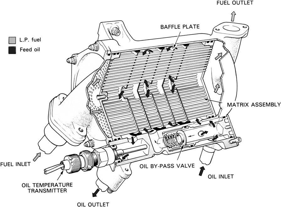
The fuel-cooled oil cooler incorporates a bypass valve fitted across the oil inlet and outlet. The valve operates at a preset pressure difference across the cooler and thus prevents engine oil starvation in the event of a blockage. A pressure maintaining valve is usually located in the feed line of the cooler, which ensures that the oil pressure is always higher than the fuel pressure. In the event of a cooler internal fault developing, the oil will leak into the fuel system rather than the potentially dangerous leakage of fuel into the oil system.
The air-cooled oil cooler is similar to the fuel-cooled type in both construction and operation; the main difference is that air is used as the cooling medium.
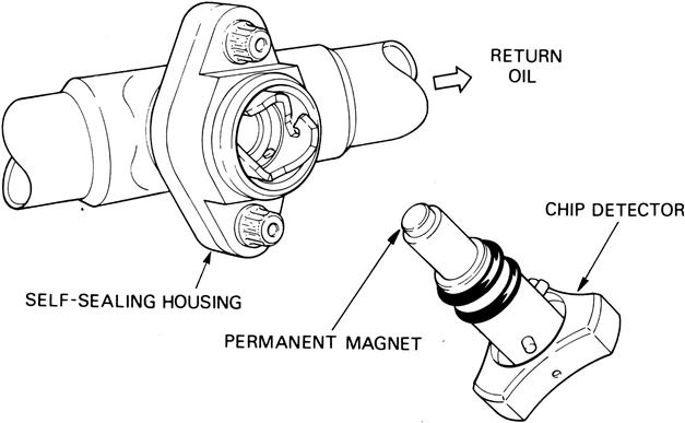
Magnetic plugs, or chip detectors (Figure 5–16), are fitted on the scavenge (return) side to collect ferritic debris from each bearing chamber. They are basically permanent magnets inserted in the oil flow and are retained in self-sealing valve housings. Safety features incorporated in the design ensure correct retention within the housing. Upon examination they can provide a warning of impending failure without having to remove and inspect the filters. They are designed to be removed during maintenance inspection, for condition, monitoring purposes, without oil loss occurring. Additionally, they may be connected to a cockpit warning system to give an in-flight indication.
Bearings
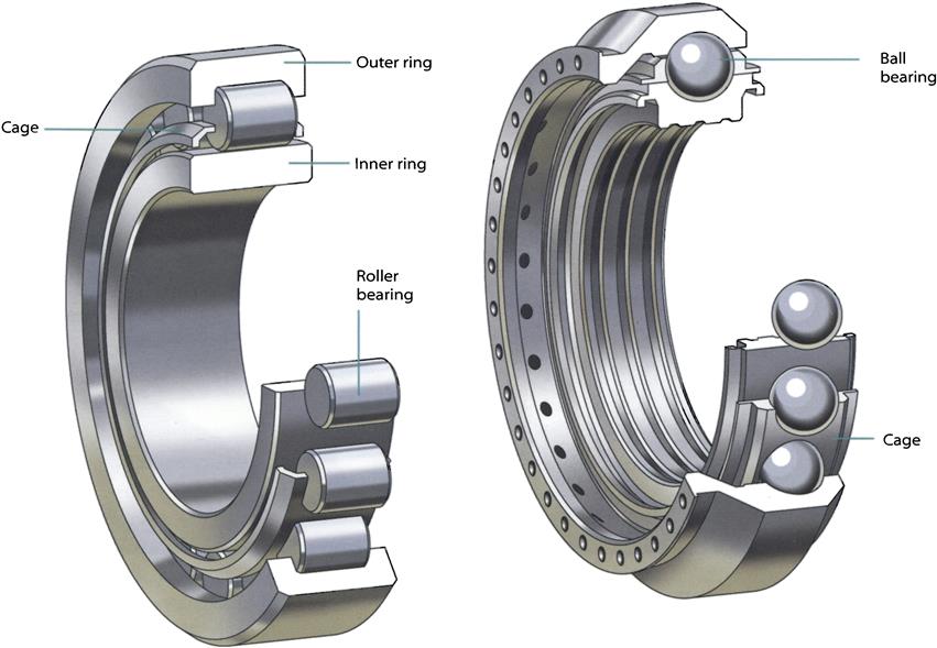
Bearings provide a means of accurately locating the rotors while transmitting high forces with very little rotational resistance. Jet engines tend to use rolling element bearings, but occasional application of plain bearings can be found. There are two types of bearing used in a gas turbine: ball bearings and roller bearings. Ball bearings use balls as the rolling elements, which, because of their shape, can withstand both radial and axial forces. This makes ball bearings suitable for transmitting thrust. Roller bearings use cylinders as the rolling elements. The rollers can transmit radial load across their diameters, but allow the shaft to slide lengthwise. Using a single ball bearing for thrust and one or more roller bearings to support a rotor allows positioning at the thrust bearing, but freedom for growth at the roller bearings.
Bearings can be used between rotating and fixed structures, or can be used between rotating components. For example, the LP shaft thrust bearing on three-shaft engines is mounted between the LP and IP rotors. All rotating shafts in the engine, including the drive shafts from the internal gearbox to the accessory gearbox and the gear shafts within the accessory gearbox, are mounted on rolling element bearings.
All rolling element bearings consist of an inner and outer race, a cage, and the rolling elements themselves. One or both of the races have a raceway formed within it to guide the rolling elements. The cage is used to maintain spacing of the rolling elements, which are trapped inside pockets. The cage has a clearance with respect to both the inner and outer races, but is primarily located by one or the other, depending upon the requirements of the bearing application. To ensure that the cage runs concentrically, the clearance between the locating lands on the race and the cage is small and well lubricated so that it operates without appreciable wear. The cage may also have features to assist in catching and directing lubrication to the rolling elements (Figures 5–17 to 5–19).
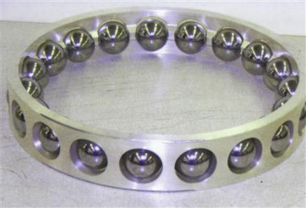
Ball Bearings
Ball bearings provide axial location for a rotating shaft, but will usually carry a substantial radial load. A rotating shaft is supported by at least two bearings: normally, one is a ball bearing and the other a roller bearing.
Main shaft location bearings are situated in the internal gearbox on three-shaft engines and on many two-shaft engines. Putting these highly-loaded bearings in a relatively cool part of the engine greatly simplifies design of the load paths through the engine structures. Accurate axial location provided by the ball bearings is essential for close control of compressor tip clearances.
Deep Groove
Deep-groove ball bearings have single-piece inner and outer rings. The cage is made, therefore, from two pieces to allow the bearing to be assembled. The inner and outer track forms are both derived from a single radius, and so the balls can only make single-point contact with each race. They are often used for applications with moderate radial loads and light axial loads.
Two-Piece Raceway Type
This bearing commonly has a single-piece outer race and two-piece inner race, although it is possible to have a two-piece outer and single-piece inner. Splitting one of the races allows the bearing to be assembled and to have a single-piece cage. The raceway in each race is formed from two radii (one for each half of the raceway) struck from different centers so that the form of the track is a gothic arch. Since one of the races must be split, the thrust load must be maintained at a high level during operation to prevent the balls from contacting the split. Therefore these bearings are used more in applications that require high thrust-carrying capacity.
The gothic arch form allows oil to be fed into the center of the inner track without the risk of damage that might result from the balls running over the edges of the oil feed holes. Supplying oil to the center of the inner race gives good lubrication at the ball contacts. This configuration is most commonly used for main shaft location bearings, as used on the Trent LP, IP, and HP main shafts (Figures 5–20 and 5–21).
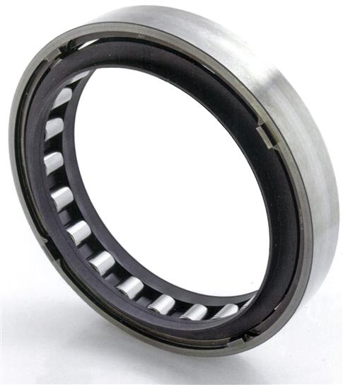
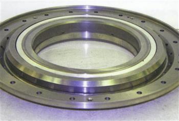
Roller Bearings
Roller bearings are used in all main shaft and auxiliary drive shaft applications to support pure radial load, and allow for axial shaft elongation due to temperature changes with no additional load effect on the bearing. They are usually located at the ends of the turbine and compressor shafts and are often mounted in a housing, but separated from it by a layer of pressurized oil known as a squeeze film damper.
In many cases, instead of having a separate inner race for roller bearings, the “inner race” is an integral part of the shaft or stub shaft. This reduces complexity, weight, and build-up of concentricity tolerances. Overall, this is cost effective, but the cost of replacement or repair is likely to be higher than for separate inner races.
Bearing Internal Clearance
Bearing diametral clearance is the total free movement between the inner and outer races in the radial direction. For ball bearings, there must be some positive diametral clearance under all operating conditions. Roller bearings and ball bearings that are mainly radially loaded benefit from low diametral clearance. This maximizes the number of loaded elements and reduces rolling element-to-race stress levels. For roller bearings, a low diametral clearance also helps to reduce the risk of roller skidding.
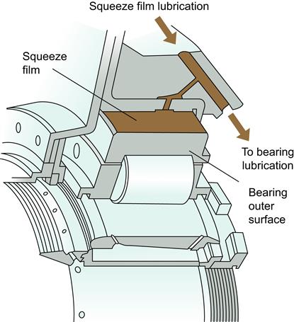
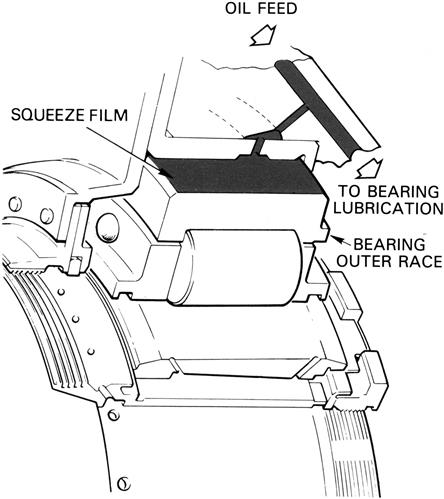
In some engines, to minimize the effect of the dynamic loads transmitted from the rotating assemblies to the bearing housings, a “squeeze film” type of bearing is used (Figure 5–22). They have a small clearance between the outer race of the bearing and housing with the clearance being filled with oil. The oil film dampens the radial motion of the rotating assembly and the dynamic loads transmitted to the bearing housing thus reducing the vibration level of the engine and the possibility of damage by fatigue.
Bearing Materials
Bearings are currently manufactured from steels that may be either case-hardened or through-hardened to suit the application. Rolling element bearings operate with high local stress levels at the contacts between the rolling elements and the races. This means that the material used must have a very high resistance to rolling contact fatigue. Other requirements of the material are a high level of hardness at the surface, high temperature and wear resistance, and often a tough core. The effects of rotation and installation fits can further increase these stress levels. Surface-hardened materials have an additional attribute: a surface that is usually in compression. This is beneficial to a surface in tension and tends to cancel out the effects of rotation and fit. Corrosion resistance and damage tolerance may be other important attributes in some applications.
Most bearings employ high-quality steels for the cage material. However, lower duty bearings may use phosphor bronze or brass cages. Silver plating and phosphate coating enhance friction, lubrication, and wear properties on steel cages.
Bearing Developments
The demands for future gas turbine bearings will be longer life, higher speeds, higher load capacity, smaller diameters, and (for aero engines) less weight. Steel processing continues to improve and is delivering cleaner, inclusion-free materials, leading to higher fatigue resistance.
Current technology goes some way to meeting these needs. However, alternative materials such as ceramics, polymers, and composites will play a future role in aerospace bearing technology, particularly in high-speed applications. They offer high strength for low weight and work well in high temperatures and poor lubrication conditions. Specialist surface treatments are also being developed that will enhance bearing performance.
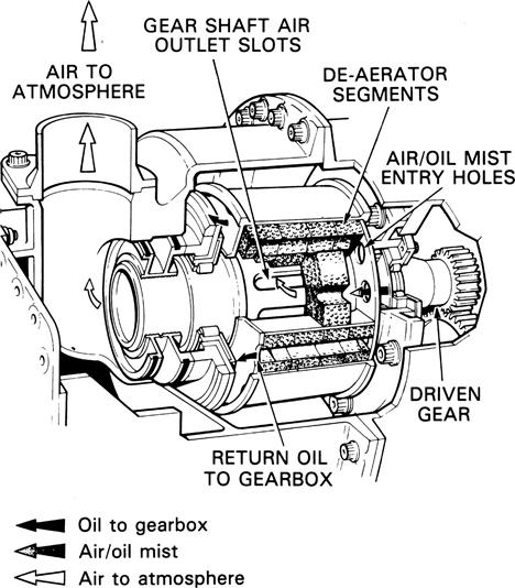
To prevent excessive air pressure within the oil tank, gearboxes, and bearing chambers, a vent to atmosphere is incorporated within the lubrication system. Any droplets in the air are separated out by a centrifugal breather prior to the air being vented overboard. Some breathers may incorporate a porous media, forming de-aerator segments, which improves the efficiency of the oil separation (Figure 5–23).
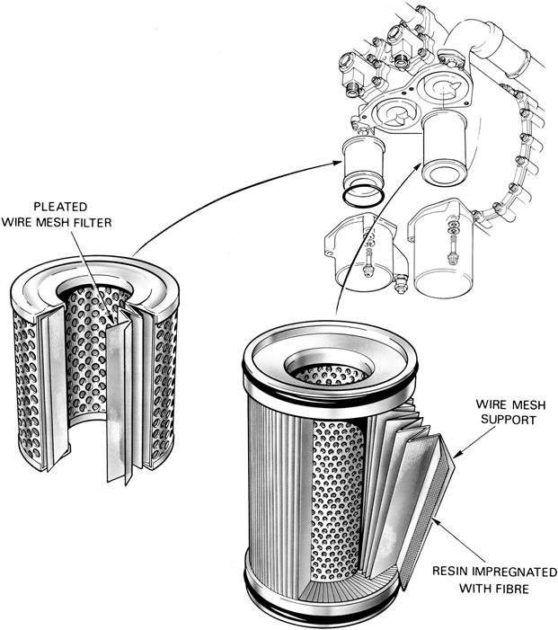
To prevent foreign matter from continuously circulating around the lubricating system, a number of filters and strainers are positioned within the system. Coarse strainers are usually fitted at the outlet of the oil tank or immediately prior to the inlet of the oil pumps to prevent debris from damaging the pumps. A fine pressure filter is fitted at the pressure pump outlet, which retains any small particles that could block the oil feed jets. Thread-type filters (Figure 5–24) are often fitted as a “last chance” filter immediately upstream of the oil jets. Sometimes perforated plates or gauze filters are used for this application. Scavenge filters are fitted in each oil return line to collect any debris from the lubricated components. An example of a pressure and scavenge filter is shown in Figure 5–25. They are invariably of tubular construction with a pleated woven wire cloth or a resin impregnated with fibers, as the filtering medium. Some filters comprise one or more wire wound elements but these tend to be insufficient for fine filtration. A “pop-up indicator” may be fitted to the filter housing to give a visual warning of a partially blocked filter.
Oil System Differences for Marine Applications
A typical marine gas turbine installation may consist of a gas turbine change unit (GTCU), a power turbine, and the associated installation module. The GTCU oil system may share oil with a hydraulic system pressurized by a GTCU-driven pump. The hydraulic system provides power to the airflow control regulator.
Module-Mounted Components
Some oil system components, such as the oil tank, may be located in the installation module for ease of access. Other components, which do not require regular attention (for example, the engine oil-pumping unit), may be located on the high-speed gearbox on the GTCU, as on an aero application.
The main filtration is carried out in the scavenge side of the system and the filter may be a duplex unit, located in the installation module. This allows the oil flow to be switched between two identical filter elements, allowing one to be replaced without stopping the engine or losing filtration. If a filter becomes blocked a bypass valve will open, allowing unfiltered oil to flow, permitting the engine to continue running with no loss of oil pressure. A visual indication of the filter condition (pressure drop) is provided to ensure that the filter is changed before bypass occurs. Instead of using the fuel (or air) supply to cool the oil, it is usual to pass seawater through a module-mounted heat exchanger.
Power Turbine (Mechanical Drive) Oil System
The power turbine oil supply system is independent of the GTCU system. Oil is delivered from the ship's supply system, through an adjustable orifice valve and distribution block, to the power turbine bearings; the oil is returned to the same supply system.
Lubricating Oils
Early gas turbines used thinner oils than those used in piston engines but were produced from the same mineral crude oil. As gas turbines were developed to operate at higher speeds and temperatures these mineral oils oxidized and blocked the filters and oilways. The development of low viscosity (thin) synthetic oils overcame the major problems encountered with the early mineral oils.
The choice of a lubricating oil is initially decided by the need to start the engine at very low temperatures, when the viscosity of the oil is high, while being able to survive in an engine environment which exhibits very high temperatures. Having met these fundamental requirements, the need to provide improved lubrication characteristics using additives must also be investigated. Special laboratory and engine tests are done to prove the suitability of a particular oil for a specific type of engine. Assessments are made as the extent to which it deteriorates and the corrosive effects it may have on the engine.
Most gas turbines use low viscosity oil due to the absence of reciprocating parts and heavy-duty gearing. This reduces the power required for starting, particularly at low temperatures. In fact normal starts can be made in temperatures as low as –40°C without having to preheat the oil.
Turbopropeller engines use a slightly higher viscosity oil due to the additional requirements of the reduction gear and propeller pitch change mechanism.
The field of lubrication is a massive one, and there are deservedly books dedicated exclusively to this topic. We will not attempt to cover all that technical territory, but there is a list of several excellent references in Chapter 20. However, in this chapter, an operator’s perspective on his turbine oil (both gas turbine and steam turbine [with steam turbines in combined cycle applications or solo] and their systems) is presented next. The original author is an oil company turbomachinery end user and reflects quite comprehensively the issues this author dealt with as an end user in the oil and gas and process (including refining industries).
An Operator’s Perspective on Turbine Oil Selection5
The answer to “how long will this turbine oil last?” varies depending on the application. Turbine oil suppliers can give fairly wide-ranging estimates, say 5–15 years, for gas turbines. An exact answer depends on many variables: water, heat, contamination, operating hours, and maintenance practices will impact turbine oil longevity. Properly tested and maintained, higher-quality turbine oils will provide longer life than poorly tested and maintained, lower-quality products. New turbine oil performance characteristics will promote longer, trouble-free service.
In turbines, what is potentially more than 100 tons of rotating steel is supported by plain bearings on a cushion of oil that is thinner than a human hair. In power plants around the world, the same fluid dynamics take place day-in and day-out without much notice. Lost revenue at seasonal peaks can be counted in millions of dollars. Poor selection and maintenance of turbine oil can result in production losses exceeding $500,000 per day.
When selecting turbine oil for steam, gas, hydro, and aeroderivative turbines, oil supplier service abilities ought to be evaluated as part of the selection process. Turbine oils differ from most other lubricating oils and one needs to understand the basics of how and why.
Steam, gas, and hydro turbines oils are R&O (rust and oxidation inhibited) oils. Turbine equipment geometry, operating cycles, maintenance practices, operating temperatures, and potential for system contamination need to be considered.
Utility steam and gas turbine sump capacities range in size from 1000 to 20,000 gallons and up. Low turbine oil makeup rates (approximately 5% per year) are easier with high-quality, long-life lubricants. Without significant oil contamination issues, turbine oil life is primarily dictated by oxidation stability. Oxidation stability is adversely affected by heat, water aeration, and particulate contamination. Antioxidants, rust inhibitors, and demulsibility additives are blended with premium-quality base stock oil to extend oil life. Lube oil coolers, water removal systems, and filters are installed in turbine lubrication systems for the same purpose.
Unlike most gasoline and diesel engine oil applications, turbine oil is formulated to shed water and allow solid particles to settle where they can be removed through sump drains or kidney loop filtration systems periodically. To aid in contaminant separation, most turbine oils are not “doped” with high levels of detergents or dispersants that clean and carry away contaminants. Turbine oils are not exposed to fuel or soot and so do not need to be drained and replaced on a frequent basis.
Characteristics of Turbine Oil and Applications
Steam Turbines
A well-maintained steam turbine oil with moderate makeup rates should last 20–30 years. When steam turbine oil fails early through oxidation, it is often due to water contamination. Water reduces oxidation stability and supports rust formation, which among other negative effects acts as an oxidation catalyst.
Varying amounts of water will constantly be introduced to the steam turbine lubrication systems through gland seal leakage. Because the turbine shaft passes through the turbine casing, low-pressure steam seals minimize steam leakage or air ingress leakage to the vacuum condenser. Water or condensed steam is channeled away from the lubrication system but some water will penetrate the casing and enter the lube oil system. Gland seal condition, gland-sealing steam pressure, and the condition of the gland seal exhauster will affect the amount of water introduced to the lubrication system. Typically, vapor extraction systems and high-velocity downward-flowing oil create a vacuum that can draw steam past shaft seals into the bearing and oil system. Water can also enter via lube oil cooler failures, improper powerhouse cleaning practices, water contamination of makeup oil, and condensed ambient moisture.
In many cases, the impact of poor oil/water separation can be offset with the right additives including antioxidants, rust inhibitors, and demulsibility improvers.
Excess water may also be removed continuously with water traps, centrifuges, coalescers, tank headspace dehydrators, or vacuum dehydrators. If turbine oil demulsibility has failed, exposure to water-related lube oil oxidation then depends on water separation systems.
Heat will also cause reduced turbine oil life through increased oxidation. In utility steam turbine applications, bearing temperatures of 120–160°F (49–71°C) and lube oil sump temperatures of 120°F (49°C) are typical. Heat doubles the oxidation rate for every 18° above 140°F (10° above 60°C).
A conventional mineral oil rapidly oxidizes at temperatures above 180°F (82°C). Most tin-babbited journal bearings will begin to fail at 250°F (121°C). That is well above the temperature limit of conventional turbine oils. High-quality antioxidants can delay thermal oxidation but excess heat and water must be minimized to gain long turbine oil life.
Gas Turbines
For most large gas turbine frame units, high operating temperature is the leading cause of premature turbine oil failure. Higher turbine efficiencies and firing temperatures in gas turbines have been the main incentive for more thermally robust turbine oils. Today’s land-based large-frame units operate with bearing temperatures in the range of 160–250°F (71–121°C). OEMs have increased their suggested limits on RPVOT ASTM D2272 (rotation pressure vessel oxidation test) and TOST ASTM D943 (turbine oil oxidation stability) performance to meet higher operating temperatures.
Changes in operating cycles are also introducing new lubrication hurdles. Lubrication issues specific to gas turbines in cyclic service started to appear in the mid-1990s. Higher bearing temperatures and cyclic operation foul system hydraulics. This delays equipment startup. Properly formulated hydrocracked turbine oils were developed to remedy this problem and to extend gas turbine oil drain intervals. Products such as Exxon Teresstic GTC and Mobil DTE 832 have demonstrated excellent performance for almost five years of service life in cyclically operated gas turbines. Conventional mineral oils had failed in one to two years.
Aeroderivative Gas Turbines
Aeroderivative gas turbines require oils with much higher oxidation stability. Lube oil in aeroderivative turbines is in direct contact with metal surfaces ranging from 400–600°F (204–316°C) typically and sump lube oil temperatures can range from 160–250°F (71–121°C). These turbines’ cyclical operation imparts significant thermal and oxidative stress on the lubricating oil. This then dictates the use of high purity synthetic lubricating oils. Average lube oil makeup rates of 0.15 gallons per hour help rejuvenate the turbo oil under these conditions.
Aeroderivative turbines operate with much smaller (than industrial) lube oil sumps, typically 50 gallons or less.
Synthetic turbo oils are formulated for military aircraft gas turbo engines identified in military (MIL) specification format. These MIL specifications ensure that similar quality and fully compatible oils are available throughout the world and as referenced in OEM lubrication specifications.
Type II turbo oils were commercialized in the early 1960s to meet US Navy demands for improved performance, which created MIL-L (PRF)-23699. The majority of aeroderivatives in power generation today deploy these Type II, MIL-L (PRF)-23699, polyol ester-base stock, synthetic turbo oils. These Type II oils offer significant performance advantages over the earlier Type I diester-based synthetic turbo oils.
Enhanced Type II turbo oils were commercialized in the early 1980s for the US Navy’s demand for better high-temperature stability. This led to the new specification MIL-L (PRF)-23699 HTS. In 1993, Mobil JetOil 291 was commercialized as the first fourth-generation turbo oil for advanced high-temperature and high-load conditions of jet oils.
Generator bearings typically use an ISO 32 R&O or hydraulic oil. The lower pour points of a hydraulic vs. an R&O oil may dictate the use of a hydraulic oil in cold environments.
Turbine Oil Procurement Standard
Steam, gas, and hydro turbine oils blend highly refined or hydroprocessed petroleum-based oils, usually ISO VG 32 and 46 or 68. Lubricant suppliers have developed turbine oils specifically for propulsion and power generation, based on turbine OEM specifications. Many turbine OEMs have moved away from specific turbine oil brand-name approvals due to improvements in specific turbine oils. OEMs recommend lube oil performance test criteria and typically ask that an oil, successful in the field, still be used even if all recommended values have not been satisfied. Industry standard lube oil bench tests reveal the performance and life expectancy of turbine oils. However, turbine OEMs and oil suppliers agree that past performance of an oil under similar conditions is the best overall recommendation.
Regardless of service type, the quality of the base stocks and additive chemistry will affect longevity. High-quality base stocks have higher-percentage saturates, lower-percentage aromatics, and lower sulfur and nitrogen levels. Additives must be extensively tested. They must also be blended in a tightly controlled process.
The key to good turbine oil is property retention. Some turbine oils have good lab test data but can experience premature oxidation because of additive dropout and base stock oxidation. Again, lube oil laboratory analysis can determine turbine oil longevity, but field experience should take precedence. Note: turbine oil suppliers offer typical lube oil analysis data to help assess predicted performance. Typical data are used due to variations in base stock variations.
Utility steam and gas turbine oils can be conventional mineral-based (Group 1) or hydroprocessed (Group 2). Conventional mineral-based oils have performed well in both steam and gas turbine service for more than 30 years. The trend toward higher efficiency, cyclically operated gas turbines has spurred the development of hydroprocessed, Group 2, turbine oils.
Most hydroprocessed turbine oils have better initial RPVOT and TOST performance than conventional turbine oils. This oxidation stability performance advantage helps heavy-duty gas turbine applications.
The oxidation performance advantages of a hydroprocessed turbine oil may be unnecessary in less demanding steam and gas turbine applications. Conventional mineral-based oils have better solvency than hydroprocessed oils. This, in turn, can provide better additive package retention and increased ability to dissolve oxidation products that could otherwise potentially lead to varnish and sludge.
Compatibility testing between turbine oil brands should also be addressed with a turbine oil specification for systems not available for a complete drain and flush. Clashing additive chemistries or poor in-service oil quality may prohibit mixing different and incompatible turbine oils. Oil suppliers can provide compatibility testing to confirm suitability for service. This testing assesses the condition of the in-service oil compared to various possible blends with the proposed new oil. The in-service oil should first be tested for suitability for continued service. Then a 50/50 blend should be tested for oxidation stability (RPVOT ASTM D2272), demulsibility (ASTM D1401), foam (ASTM D892, Sequence 2), and the absence of additive package dropout as witnessed in a seven-day storage compatibility test.
Lube Oil System Flushing
Turbine lube oil system flushing and initial filtration should be addressed when selecting turbine oil. Lubrication system flushing may be either a displacement flush after a drain and fill or a high-velocity flush for initial turbine oil fills. A displacement flush is performed concurrently during turbine oil replacement and a high-velocity flush is designed to remove contaminants entering from transport and during the commissioning of a new turbine.
Displacement flushes using a separate flush oil remove residual oil oxidation product that is not removed by draining or vacuum. A displacement flush utilizes lubrication system circulation pumps without any modification to normal oil circulation flow paths, except for potential kidney loop filtration. This flush is typically done based on a time interval vs. cleanliness (particle levels) to allow removal of soluble and insoluble contaminants that would not typically be removed by system filters.
Most turbine OEMs provide high-velocity flushing and filtering guidelines. Some contractors and oil suppliers also give flushing and filtering guidelines. Often during turbine commissioning, these guidelines are scaled back to reduce cost and time. There are common elements of a high-velocity flush that are generally supported by interested parties. There are also some procedural concerns that may differ and are addressed on a risk vs. return on investment basis.
Common elements of mutual agreement in high-velocity flushing are as follows:
• Supply and storage tanks should be clean, dry, and odor free. Diesel flushing is not acceptable.
• Two to three times normal fluid velocity achieved with external high-volume pumps or by sequential segmentation flushing through bearing jumpers.
• Removal of oil after flush is completed to inspect and manually clean (lint-free rags) turbine lube oil system internal surfaces.
• High-efficiency bypass system hydraulics eliminates the risk of fine particle damage.
Possible supplemental or alternative elements of a high-velocity flush are as follows:
• Use of a separate flush oil to remove oil soluble contaminants that can impact foam, demulsibility, and oxidation stability.
• Need to filter the initial oil charge at a level consistent with the filtration specification.
• Thermal cycling of oil during the flush.
• Pipe line vibrators and the use of rubber mallets at pipe elbows.
• Special cleanliness test strainers and sampling ports.
• Cleanliness criteria for flush buy-off.
• Lab ISO 17/16/14 to 16/14/11 acceptable particulate range.
• Use of on-site optical particle counters.
Prior planning and meetings with construction, startup, oil supplier, and the end user should be scheduled in advance to build consensus on these flushing procedures.
A good practice for turbine oil performance documentation is to take a 1-gallon sample from the supply tank and then a second gallon sample from the turbine reservoir after 24 hours of operation. The recommended testing is consistent with turbine oil condition assessment testing:
Development Case study: Oil-Free Bearings
Another newer innovative design feature (still in development) that addresses the need for cooling, and as it turns out also lowers fuel consumption, is the oil-free bearing. This design feature is not yet commercially available on commercial gas turbines, but it does need to be considered in the future, particularly for aircraft engine applications. The work from which the extracts on this topic are drawn was published by NASA in 20106. Since then, the budget to continue with this work by this source has been reassigned elsewhere. This is the kind of development that will be taken up again in better economic times because of the fuel savings realized. There is also the matter of weight savings and particularly in aeroengine applications, this is important.
The term oil-free turbomachinery has been used to describe a rotor support system for high-speed turbomachinery that does not require oil for lubrication, damping, or cooling. The foundation technology for oil-free turbomachinery is the compliant foil bearing. This technology can replace the conventional rolling element bearings found in current engines. Two major benefits are realized with this technology. The primary benefit is the elimination of the oil lubrication system, accessory gearbox, tower shaft, and one turbine frame. These components account for 8–13% of the turbofan engine weight. The second benefit that compliant foil bearings offer to turbofan engines is the capability to operate at higher rotational speeds and shaft diameters.
While traditional rolling element bearings have diminished life, reliability, and load capacity with increasing speeds, the foil bearing has a load capacity proportional to speed. The traditional applications for foil bearings have been in small, lightweight machines. However, recent advancements in the design and manufacturing of foil bearings have increased their potential size. An analysis, grounded in experimentally proven operation, was performed to assess the scalability of the modern foil bearing. This analysis was coupled to the requirements of civilian turbofan engines.
The application of the foil bearing to larger, high bypass ratio engines nominally at the 120 kN (∼25,000 pound) thrust class has been examined. The application of this advanced technology to this system was found to reduce mission fuel burn by 3.05%. The present study is grounded within the NASA Fundamental Aeronautics Program – Subsonic Fixed Wing Project and its focus is limited to what is termed “N+1” propulsion systems. These systems are representative of the next generation of civilian aircraft. In terms of the propulsion system, this implies two spool, direct drive turbofan engines having bypass ratios in the range of 8–12.
Future studies will consider advanced propulsion systems in which a new design space is enabled by gas foil bearings. By considering clean sheet propulsion system designs that are not limited to current engineering design practices, enhanced benefits attributed to this bearing technology are expected in future system studies. Typically, gas foil bearings are used in much smaller turbomachines where the rotors are lighter, rotate faster, and where system auxiliary weights (such as the lubrication system) are a significant fraction of the overall system weight. However, advances in load capacity and scalability of the gas foil bearing warrant further study into larger systems. The gas foil bearing is the key technology in what has become known as “oil-free turbomachinery.”
Oil-free turbomachinery, within the context of this study, is defined as highspeed rotating equipment operating without oil lubricated rotor supports, such as bearings, dampers, seals, and other components required in conventional turbo machines. Through the elimination of the lubricating oil, rolling element bearings, and the requisite supporting subsystems it is envisioned that revolutionary improvements in performance, efficiency, and reliability of turbomachinery propulsion systems can be realized. The enabling technology of oil-free turbomachinery is the modern development of high speed, high temperature, and high load capacity foil bearings.
Among the benefits of oil-free bearings are reduced machine weight due to the elimination of the oil systems, removal of the traditional diameter – rotational speed limit (DN) imposed by rolling element bearings, and a synergistic use of working fluid as a lubricant enabling a contaminant-free working fluid. However, in order to realize these benefits, foil bearings must be able to support the required machine load and operate reliably and without burden to machine performance.
A generic foil journal bearing is shown in Figure 5–26. It consists of a rigid, stationary shell that contains a compliant foundation. This compliant foundation can take different forms, but is usually portrayed as a thin layer of corrugated metal referred to as the bump foil. A smooth foil, known as the top foil, is then fastened to one edge of the bump foil. A rotating shaft fits inside the top foil. Foil bearings typically operate without static clearance between the stationary top foil and rotating shaft. In fact there is often a preload force between the two parts. This static preload is unique to foil bearings and presents a technical challenge for both machine startup as well as analytic modeling. At a certain speed known as the lift off speed, the hydrodynamic gas film force overcomes the preload force and complete fluid film lubrication is established.