
The Business of Gas Turbines
Abstract
Business decisions in any sector involve much subjective thought, most of it rooted in the decision maker’s personality, culture, and life exposure to that point. Both personal experience and statistics offer many opportunities for brilliance or failure. Also, what is “right” one year is “wrong” 10 years from now, as technology, corporate, and national alliances change. This chapter includes studies that detail the economics of specific cases. However, technical papers tend to leave out all but the bare technical and economic bones. Any business is far more complex than that. It involves cultures, alliances, rivalries, combatants, both old and new, seen and unseen.
Keywords
Business climate; culture; risk assessment; market assessment; plant siting; design development
“Hear reason, or she’ll make you feel her.”
—Benjamin Franklin
Business1,2 decisions in any sector involve much subjective thought, most of it rooted in the decision maker’s personality, culture, and life exposure to that point. Despite any changes that prolonged war, the increasing awareness of climate change, the impending emissions economy or expansion of same (in some countries), the essence of how gas turbine business flows or stagnates hasn’t changed much since the first edition of this book.
Both personal experience and statistics offer many opportunities for brilliance or failure. Also, what is “right” one year is “wrong” 10 years from now, as technology, corporate, and national alliances change.
This chapter includes some excellent studies that detail the economics of specific cases. However, technical papers tend to leave out all but the bare technical and economic bones. Any business is far more complex than that. It involves cultures, alliances, rivalries, combatants, both old and new, seen and unseen.
The culture within the USA with respect to acknowledging the fact of human effects on climate change and increasing greenhouse gas emissions has been evolving. Several factors contribute. Organizations like the Sierra Club have been attacking coal, resulting in some coal plants and mines being closed. Some power plants across the country have converted their coal-fired steam turbine plants to GT CC plants, raising fuel efficiency and curtailing emissions. Some have converted coal-fired steam turbine plants to natural gas-fired plants, which while it curtails emissions to some degree, does not raise efficiency, which is the main “gain” factor in reducing emissions.
Meanwhile, the politics within the USA will not let coal die, despite its renewed gas supplies. The FutureGen project will feature oxycombustion of coal (instead of the originally planned IGCC). The US DOE and EPRI continue to work on USC (ultra-supercritical steam) and advanced USC steam, which plan steam temperatures of about 760°C.
SC steam has been around since the 1950s and because of its coal-rich resources, China made some great strides in this area. EU OEMs (original equipment manufacturers), like Siemens, supplied some of their SC and USC steam turbines, but China also has her own steam turbine manufacturers.
One of the main features of FutureGen will be the CSS (carbon sequestration and storage system) that will be part of the power generation system being built and relatively “new” to the USA. That said, corporations like Statoil (Norway) and Vatenfall (Sweden) have been practicing CSS for decades. As Scandinavia practices a more environmentally conscious culture, people there did not flinch at SOx and NOx taxes, even when they were among the first in the world to levy them.
There seems little doubt at this point that the world is headed towards a carbon emissions trading facet in the global economy. The details have yet to be ironed out. Meanwhile organizations like IEA collect and feature the work of pilot projects like FutureGen that occur elsewhere in the world. Now China and the USA have a cooperative agreement for working together on certain CSS work.
All this does not mean that renewables have been abandoned, although the development funds for them were decidedly diminished over bad economic years and they still are not at the top of any major economy’s list (except for countries like Denmark of course). That said, smart grids may do a great deal to revive interest in these small and intermittent producers of power. Power production conglomerates think increasingly in terms of system integration (STs, SC STs, GT CCs, GTs, and renewables in concert). There remains the question of the archaic and crumbling transmission line infrastructure that traverses so much of the USA, but fortunately that’s a question that this book can avoid.
The “macro” business picture can periodically be dictated by wars (for instance large new orders of turbomachinery slated for the United States rebuilding program in Iraq), trading bloc protocols (EU, ASEAN, NAFTA), or in the case of the United States, a national penchant for moving toward countries with cheap labor (migration of manufacturing jobs to China and India). The “intermediate” business scene is painted by larger corporations taking on smaller ones (for instance, GE buying Rotoflow and Bentley Nevada to name a few), large corporate role expansions (like OEMs becoming IPPs, oil companies becoming IPPs), and expanding global presence (like the major OEMs’ growing presence in NICs, like China and India).
However, the detailed (“micro”) business scene is dictated by the working engineers, regardless of their function: design, operations and maintenance, and so forth. This, of course, is to some extent limited or promoted by circumstances beyond our control. The field of operations (including maintenance, R&O, and troubleshooting/failure analysis), however, is where the most visible and controversial examples of engineers affecting corporate business occur.
For most turbomachinery engineers, some of their work, particularly if they are in operations, has direct, immediate (or almost immediate), and major impact on their customers’ net operating profits. Selected at random, some of the cases in point stretch from a purge oil system that threatened to shut down a 120,000 oil barrels a day plant, to an aeroengine failure that threatened to ground a world fleet, to small(er) issues like an aeroengine that had failed the post-overhaul test six times. Solving each one involves far more than just technical facts. So, before the case studies in this chapter, a summary of what that case paper’s title means in the context of work in the power generation, oil and gas, and aeroengine sectors is probably useful. Note that the experience and observations that follow are based on my working notes and experience [14-2]. The reader’s experience may differ. However, the points where a reader differs are just as helpful as those that concur. The overall subject of business is highly subjective. Disagreement and controversy broaden one’s frame of reference and are useful educators.
The gas turbine engineer needs to maintain a broad base of reference. People everywhere tend to keep their gas turbines until they literally have nothing more than they can move or operate with them, and even then, they may try to resell them for “spares.” Engineers who work in performance optimization and troubleshooting may find themselves developing a repair process for a superalloy component one day. The next day, they may be designing steam injection for gas turbines made from materials that are 1960s in composition, that operate on very low TITs, just to get another 20% power out of an ancient fleet and not need to install a new machine for additional power, in a crowded plant.
Contemporary Business Climate
The world is a tumultuous place some years into a new century. With an item such as the gas turbine, the fuel selected for the gas turbine system is key to the gas turbine's success and competitiveness.
Fuels
With the first edition of this book, the gas turbine fuels of choice were gas, clean liquid fuels, residual or process waste, such as paper liquor (with many changes to the fuel system). With coal gasification making the strides that it has, the gas turbine can square off with the steam turbine even in coal rich countries. Just one indicator of this fact is the following news clip: “Siemens3 Energy4 is adding a new high-performance model, the SFG-850, to its range of entrained-flow gasifiers. The SFG-850 is designed to enhance the profitability of future gasification plants by reducing specific plant costs, along with the associated production costs of synthesis gas. An SFG-850 gasifier can convert around 3,000 metric tonnes of coal per day into more than 5 million standard cubic metres (Nm3) of high-quality synthesis gas…. In addition, Siemens can offer an optimised configuration of gasifiers and latest-generation Siemens gas turbines with the new SFG-850 gasifier. This will make power generation in IGCC (Integrated Gasification Combined Cycle) plants more economically appealing and, hence, more competitive than current solutions.”
Further material on the gas turbine's increasing adaptability to a widening range of fuels can be found through the rest of this book, particularly in chapter 7 (fuels).
War
At the ASME IGTI TurboExpo 2002, in the year prior to the second US-Iraq war and the year after the 2001 US-Afghanistan war, the large OEMs admitted to a major downturn in orders for the following two years. Major unrest in the Middle East, Afghanistan, India, and Pakistan continues. Iran’s national pride in accumulating centrifuges to make power-generation-grade uranium is evident. Estimates as to when they will have enough centrifuges to get that up to weapons grade vary. Meanwhile, a section of Pakistan has reverted to Taliban life philosophies and North Korea is testing nuclear missiles. Central Europe remains uneasy and relatively poor. Russia is booming, despite pockets of civil unrest. The unofficial unspoken reaction to all of these happenings by some has been “if it takes war[s] to make up for our lost orders of a few years ago, then bring on war.”
In some cases, such as in Iraq, the need to develop some infrastructure hastily is so great that there are orders for old models. Some of these may have been “lying around” in some “excess equipment yard” waiting to turn a larger profit margin than possible if the buyer were a poorer country or one not being funded by the United States.
Development and Delivery Lead Times
The gas turbine business demands a massive investment for new or expanded installations. The lead times with gas turbines and gas turbine systems are much larger than they are with turbines for “renewables” such as wind (partly because the unit power sizes are on a ratio of anywhere from 1–300 compared with a typical wind turbine). Also, unlike energy sources like wind turbines, one cannot just buy major components from other manufacturers, assemble them (partially on site), and start producing power. With gas turbines, the extent of integrated assembly of controls and hardware, as well as systems testing, which has to occur in the OEMs facility, prior to shipping, places the gas turbine at a disadvantage in an unstable and fragmented world. Such will remain the case, even if US gas prices drop.
Conferences as Harbingers
ASME’s IGTI annual conference frequently heralds shifts in the gas turbine business. As of the year 2000, the reduced participation of large gas turbine OEMs in the exhibit section of the conference became increasingly marked. The IGTI annual conference in 2002 saw an exhibit with relatively small participation from large OEMs (it had been shrinking for several years), and when they did appear, it was with a niche-market developed component, such as Pratt and Whitney exhibiting new brush seals it developed. Smaller firms with cutting edge products that give OEMs an edge, such as optical pyrometers, and new twists to online condition monitoring systems fared well.
PowerGen5 conferences continue to be a hive of activity in the US and other venues. The conferences certainly host large exhibit sections and attendee groups that number in the thousands.
At one point, in the 1980s, the ASME IGTI conference also hosted about 5000 engineers annually, when it was a meeting that catered more to end users than researchers and academics. Today, OEMs, individual firms and researchers that work on the cutting edge of their fields still patronize the conference, but its attendance numbers have shrunk, since it began to feature more research and academic work. The exhibit area has shrunk correspondingly.
At the 2002 IGTI conference, and in subsequent years the shift in emphasis became increasingly marked. Even in the applications area, the presenters with an academic background formed an unusually large part of the overall content. OEM and end-user originated papers made up a smaller percentage of the overall technical paper roster. The end-user and OEM papers tended to be on newer technology, such as hybrid systems. Fuel cell technology, in combination with gas turbines, is favored by legislative trends toward more environmentally friendly technology. Indeed legislation dictates that the energy mix in the United States should aim for 20% renewables by 2020. Other countries will follow suit. Some countries will exceed this target appreciably: consider Denmark and its 50% wind energy power mix by 2020.
Around 2004, the IGTI gave up trying to hold its design and end-user communities together in one meeting. Deciding that end users preferred a more practical meeting, IGTI started end-user annual meetings, generally in the same location as a larger meeting, such as Penwell's PowerGen. The “design types” IGTI meeting is held separately. The significance of this to the engineering world is that IGTI is one of the few engineering associations that present juried papers, each with three preprint reviews. This fact served the gas turbine community (and IGTI) particularly well in the 1980s and 1990s. It provided an optimum climate for “mixed” industry sector attendees (land-based, mechanical drive and powergen, as well as marine, and aviation) at the panel session6 that ran for 19 years (1985 through 2003): ECMS as GT ECMS as They Relate to Life Extension of Gas Turbine Components. Attendees were keen to learn from other sectors and “not reinvent the wheel” in their own.
OEM Acquistion strategy, National and International trends
Larger OEMs have made several acquisitions of smaller or medium sized support system manufacturing companies. This may be to maintain a competitive advantage with the ownership of support systems that they used to purchase. (Consider GE’s purchase of Bentley Nevada and Altair Filters, UK.)
Some OEMs may be keen to absorb as much in the way of high-tech niche products that will save them engineering R&D time, when the market comes back. And come back it always does, if often in unsettlingly short spurts that do not always match the lead times required to turn out a gas turbine, especially ones over 200 MW. That said, some OEMs are scaling down, selling off divisions of well-engineered gas turbines to other OEMs. The location of OEM divisions/management can shift and with that, corporate culture may also change.
The balance of overall engineer populations continues to shift. China turned out five times the number of engineers than the United States in 2005. That figure rises to 10 times if you adjust the US number for foreign students that cannot get US work visas in wartime. India graduated about half the engineers China did. Especially with what were once US jobs in manufacturing (of items that include gas turbine systems) reaching their shores, it is likely that the Asian engineers will come to know what the insides of turbomachinery look like sooner than some US counterparts.
In terms of the mechanical-drive gas turbines used in gas and oil production, the overall global gas turbine market is likely to stay stable to growing for at least the next decade. Business gurus promise that the US consumer will feel “pressured enough when gas goes from $3 to $4 and $5. That’s when you’ll see a massive change in the US consumer.” No marked trend was visible when gas prices did rise and when they fell again, with the advent of fracking, the behavior of the US consumer did not seem markedly different.
The recent increase in natural gas supply from fracking has both consumers and OEMs optimistic. The exceptions are environmental groups who note the problems that small contractors (who hold themselves perhaps to a lesser standard than a large oil company would) can cause with their practice of the fracking process.
The small (smaller in MW) gas turbine market for ferry, naval ships, small power generation applications (including offshore platform and merchant power “portable skids”), and mechanical drive applications grows, as the “news items” sections in the trade journals indicate.
The military aircraft engine market was stable to growing till about 2008 in wartime-induced sales, but that does not do much for improvements in the optimized design of aircraft engines as a whole. Not that long ago, the flow of technology went from NASA via military aircraft engines to commercial aircraft engines to aeroderivatives to industrial models. At some point in the last decade, commercial aircraft engine development got ahead of military engine development and recent wars have not changed that on a macro scale. Defense budgets are being cut notably. As of 2014, the US military cut the number of Osprey aircraft it ordered to half.7
Where is this taking the world? Inside of the next three decades, probably to the age of smaller distributed land-based power, and ultimately the personal turbine (PeT). PeTs, at some point, will become as prevalent as PCs now are. The rest of the global power mix will consist of some large plants, particularly in the newly developing countries, such as India and certain countries in Latin America, where the power wastage with faulty and badly designed transmission systems is currently as high as 10–30%.
The gas turbine, in all sizes and models, will continue, wars notwithstanding, to flourish because of their application potential in all sizes of aircraft and marine vessels. The ability to take an aeroengine model and adapt that for ground-based application will continue with a shorter time span for designing the transition. There may be some grassroots land-based designs that can be adapted for fitting into an aeroengine nacelle. However, more about all this in the chapter on the future of gas turbines.
Culture
Culture is an extremely complex factor that can rule business and technology outcomes. Industry subcultures vary as does the industry's treatment of and response to, gas turbines. The subculture varies within each industry. Within the military, the coastguard and the army have different procedures and preferences regarding what may operationally be similar engines. The powergeneration sector varies from the mechanical drive gas turbine industries (which include oil and gas, refining, process). Within for instance oil and gas, the “conventional oil and gas” operators think differently from those who make synthetic crude for instance. These cultures blend with national cultures to form their own unique stamp.
International conglomerates, within and outside of OEM conglomerates, form very different schools of thought. The consortium that makes the IAE V2500 engine have different philiosophies from the one that makes the rival CFM 56 engine. When OEMs buy a division in another OEM, the resulting “sub-company” may find it takes years for its new culture to be established. This can happen even if the companies are from the same country. An end-user who owns a gas turbine system that he bought as a European Gas Turbine model or later as an Alstom acquired model may find both advantages and disadvantages with Siemens acquisition of that model, in terms of component updates, potential for complex repairs, servicing.
In part because gas turbines are expensive items to manufacture, operate, and overhaul, many divisions of, or entire companies of gas turbine manufacturers are bought out by or merge with larger manufacturers. Rolls Royce bought Allison. Siemens merged with Westinghouse. Brown Boveri became Asea Brown Boveri (ABB), which merged with European Gas Turbine (which once was Ruston), which then merged with Alstom to form ABB Alstom, which then changed its name to Alstom, the Swedish division of which was bought by Siemens. Profit margins are hard won. Costs per pound of thrust (or horsepower or kilowatt) with manufacturers, costs per fired hour with operators, and percentage net profit per overhauled engine with repair shops are watched closely by eagle-eyed “bean counters.” As frequently happens in a highly technical business, the value of the guidance financial gurus provide is directly proportional to their technical knowledge. With gas turbines, engineers, particularly those with a broad background that includes design, repair, and operations, make the best marketing or business guides.
Historically, European and Japanese firms drew their business analysts and sales force from those with engineering backgrounds, the broader the better. US firms have been more inclined to employ business or finance “purists,” often to their detriment. Europeans are now trending more toward the US management model, which may not help increase long-term profits.
Repair and Overhaul Shop Culture
Gas turbine overhaul companies are constantly reorganizing, changing ownership, “going under,” or all three. It is possible to have a “small” repair shop. The shop may deal with only one or two repair processes, such as heat treatment or welding, and not have to accumulate the capital overhead an OEM needs for a comprehensive shop. When the shop gets successful, particularly if it developed some unique process, a larger shop or an OEM may buy the shop to extend its potential in-house work scope.
The other important factor in the business of gas turbines is one’s network. The gas turbine world, for all of the gas turbine industry’s growth, is basically small and, in any one specific subsector, for instance, aircraft engine repair and overhaul, all the main players know each other. Each subsector has its own unique culture. Some subsectors are friendlier than others. In aircraft engine overhaul, for instance, I always found that rival shops would sell each other a spare part that the other needed desperately (and expect the favor to be remembered and returned). In the oil patch, however, I recall a rival company flatly refusing to sell my company a couple of land based mechanical drive gas turbine packages for which they had no use and had left sitting in the desert, even for a most reasonable sum. (The two oil companies have since merged, which makes the tale all the more ironic.)
In this contemporary global village, recognizing culture is crucial to business success. The 1980s and 1990s saw the turbulent demise and ascendant of many overhaul facilities, particularly in the aviation business. Those shops, managed by staff who had prospered through the 1960s and 1970s, some of them getting away with a “local” client base (say, US domestic only) and bullying their small, foreign client base (“behave yourself or I won’t fix your engine”), may have been bewildered by what the 1980s brought. If they were and did not react quickly, they could have found themselves out of business in a decade or two.8 Excess equipment facilities made it possible for small repair shops and “fly by nights” (short lived) to turn a profit and exert “guerilla warfare” tactics in some cases. They might dent the work order load of one of the large shop’s business centers, say, the plating shop or the heat treatment department, or they might form an alliance to get work items that the large shop could not perform more profitably.
I recall the massive aeroengine overhaul shop I worked for in the late 1980s, subcontracting some EDM drilling work to a tiny local shop. We had the equipment in-house, we just took too long and used too much time and personnel to get it to the right work stations in our shop.
In the US business climate of the 1980s, it became critical to observe the cultural preferences of international clients during all phases of the relationship, to remember that European and Asian clients ask technical questions that may be beyond the capability of a nonengineer sales force. Rival European, Asian, and Canadian facilities knew this and had adapted. It was essential to know that the equivalent of US “blue-collar” workers in Europe were “craftsmen,” who were probably in the same union as their engineers. It was bad business to not realize that 1980's US mechanics might often be, veterans of the Vietnam war, who wanted, their management to properly motivate as well as train and compensate them. Unlike the traditional postwar Germans and English, they would not shift into “autopilot” if they disrespected their management, just so everyone could keep their jobs. Japanese executives roll up their sleeves, get on the floor with their people, and start suggestion boxes toward which they demonstrate a commitment. The US workforce is poorer in this category of executive. However, when they have a “people’s person chief,” it shows. As was evident to all who watched Herb Kelleher of SW Airlines offer his shareholders a three for two split in 2001, even as rival airlines, overhaul shops, and support businesses were forced to close their doors.
In these days of mega-corporations, portfolio diversification, takeovers, and mergers are common. Sometimes, successful large corporations are tempted into an acquisition or set of acquisitions that gets away from their core competence. As the stock exchange “graveyard” and “just treading water” lists reveal, acquisition is not always an exercise in prudence. Some such ambitious ventures did not get as far as mergers or joint ventures with OEMs. Instead, companies like Ryder concentrated on acquiring aircraft engine overhaul shops in the 1980s. After all, a gas turbine overhaul shop is really just part of the transportation business right? Wrong! Besides, the “products” from aeroengine overhaul shops are vastly different from the orderly sameness of a manufacturing facility or the routine of truck or school bus rentals. This feature is amplified in the case of an independent overhaul shop that has a dog’s breakfast of small customers who may own just a few engines (sometimes, only one plane) and a few large airline customers who sometimes grace them with their “overflow.” Then, you not only have a different culture “on the shop floor” but every customer, from Chile to Thailand, adds its own cultural profile to daily operations.
Military versus civilian mandates make different cultures, too. One of the engines from the “old” Airforce One arrived on my former nightshift beat also came with an NCO (non-commissioned officer) who watched it faithfully and mopped up a grease spill if he saw one. On the other hand, a freight hauler like Federal Express might not send a rep into an independent shop to steer it through overhaul and may want to only “make the 500 operating cycles that’ll take us past the Christmas season.”
Degree of knowledge can create major cultural barriers. I was once berated for scrapping a critical turbine disc that someone had forgotten in the acid bath. It should have been out of there in about half an hour, but it was not. I didn’t like my hydrogen embrittlement odds. Another engineer said “it looks just fine” and took it off scrap status. He did not want further dialogue. The disc looked fine—on the outside. The decision makers were not degreed engineers, and those that were may not have had to study metallurgy. The good news is that, if hydrogen embrittlement does not “get you” in fairly short order, the “heat treatment” from just the gas turbine hot section operating temperatures will cause the troublesome ions to lose their problem potential over time. I never heard about that particular engine failing, so that customer, and the shop, were lucky that time.
It is always a customer’s responsibility to “beware” as a buyer; in other words, never assume your seller has the same values as you. The customer may be someone who “sticks to the work scope (or contract)” but his seller may be of the school that “sells what [it] can get away with.” As a case in point, I once suggested we ask for a work scope extension on some used engines that had been bought by a customer, after I had seen a couple of them opened up. The seller of said engines had claimed it had completed an “ESV2” overhaul on all of them. ESV2 was Pratt and Whitney shorthand for a very thorough overhaul. So those engines ought to have looked, if not new, then very clean. However, when we opened them, we found cracks in the diffuser case, missing internal turbine air seals, and a bunch of other transgressions.
If that was an ESV2, the claimants of same were, no doubt, tooth fairies. The unsuspecting customer had specified a quick “look see” work scope, which demonstrated great trust and a complete lack of knowledge of the seller. My overhaul shop employer could comply with that work scope and be, technically at any rate, within his rights to not inform them of the mess. At that time, I was sole engineering support to an entire second shift of about 250 mechanics. We worked when all the other engineers, customers, and other staff had left for the day (except for about a two-hour common timeslot). My own “culture” could not let what a couple of floor supervisors politely called “ratshit” slide. Despite the flimsy work scope that essentially asked me to do nothing, I provided many graphic photographs that the customer’s contact engineer could include in his final report. I also stuck a copy of the pictures in the turnover log, as my position did not liaise directly with the customer or write final reports. Whether the customer had enough technical background to read the glaring evidence in the photographs or removed the engines from service henceforth and shut up to save face, I do not know.
Sense of community within each company varies globally. An overhaul shop in Scotland does not think or react like one in Texas. If acquired by the same owner, the executives may see themselves as jockeying for position. Frequently they do.
When Ryder (known for their school buses and trucks), decided to buy Aviall in the 1980's, (as distinguished from the Aviall of today, which is more a parts supplier and the small remainder of what was once Ryder Aviation Services), then the largest global independent overhaul facility for aircraft engines. Prior to 1986, the firm serviced industrial engines as well. This presumably was to extend Ryder’s reach within the global transportation sector. All the cultural implications may have been news to some of chairman Tony Burns' key decision makers. When he added what was the former British Caledonian Airways facility in Scotland, to Aviall’s assets, much of this potential melee might still have been a mystery to key personnel. So it was that an overhaul facility with a combined shop capacity of about 1000 engines a year and a stable share value of about $24 at the end of 1991, was divorced by its Ryder parent in the face of abysmal losses a few years later. The “new” corporate stock that fetched about $14 on initial offering would have difficulty raising between $5 and $7 just a year later. A relieved and helpless management sold out about then. The new Miami company management struggled with what was residual debt load, probably some inherited customer bad will, a different worker culture, or all three. It, too, sold out. The new owner, General Electric, had other shops to farm the work to, if it pleased. The aircraft engine overhaul world rumbled, raised eyebrows, found alternative shops, or used more than one shop; then all was “business as usual” again. In May 2005 or thereabouts, GE closed that shop’s doors forever, keeping just the engine test cells. Assets that supported their CFM line overhaul were probably transferred to their other shops. The tooling for the V2500 engine line (I had commissioned that program in 1991 with the first engine input from Indian Air), a rival to the CFM56, was sold to Pratt and Whitney.
End User or Operator Culture
Can such a stew of cultures be managed and turned to advantage? Southwest Airlines is living proof that it can. Whether you’re an overhaul shop, an end user/operator, or OEM, the answer is emphatically, “Yes.” The proviso is, however, that you must have the leadership of a Herb Kelleher or a Robert (“he’s a son-of-a-bitch, but he’s our son-of-a-bitch”) Crandall to make it happen.
With end user/operators, commercial size and global business affect the worker’s life and therefore the corporate success and synergy. Before conventional oil prices hit the floor in the early 1980s, I enjoyed working for them. Even in the more stringent tax environment in Canada, money spent on maintenance came off pretax gross revenues, and as long as oil prices stayed high, we never had to stay in less expensive hotels or rent the smallest cars. Even for the environmentally friendly types, car size was a consideration if you were driving out to fields over a mix of snow and black ice and you wanted a car that would “hold” the road.
It behooves employers to recognize synergy potential with its individual employees and their working circumstances. Employees need to return the favor. Some people thrive on pioneer type field projects. The more difficult the circumstances the better. Syncrude’s first synthetic crude (oil sands) 170,000 barrels-a-day facility in northern Alberta, Canada, worked through eight-month winters with average temperatures of –30°C to get commissioned on schedule in 1977/78. The average age in what was then a 35,000-people strong boom town was 15. A boy scout troop made its money for airfares across the country by collecting empty beer bottles that littered the highway between towns and the weekend playground (all things are relative) that was Edmonton. I went to the local pub only if I had many friends for company. They had shooting matches in there, not all of them friendly. The workforce stuck together through years of 16-hour days and went cross-country skiing or curling on Sundays. We were rock solid as a community, in and out of the work place.
The plant cost about $4 billion in 1970s currency and most of the critical machinery was a prototype in some way. Many of us had some of our most valuable working years on that project. The learning intensity on subsequent projects, under more “structured” environments, curiously, often is reduced.
Those of us involved with rotating machinery at the Syncrude of the late 1970s found ourselves rewriting the Exxon, Shell, and Gulf bibles for prototype machinery. That machinery is no longer “different” today. Faced with the “oil down pipeline” date, as well as OEM puzzlement and caution in the face of unanticipated obstacles that would require machinery design changes, we made swift, sweeping changes to machinery and plant systems. That may have cost us heavily, had they not worked.
Today, many oil companies in the Ft. McMurray area are building other plants, but the early 1980s saw a temporary setback in oil sands and all nonconventional energy development because of the global oil prices crisis. Had this not happened, the use of nonconventional fuels, such as orimulsion (the Venezuelan equivalent of synthetic crude) in gas turbines, would be much further along.
Money Makes Attitudes
As a propulsion systems manager for the Transport Directorate in Air Command for the Canadian Air Force, I had six aging helicopter engine fleets and four NCOs to supervise. Later in my three-year term, there would be a budding engine program newcomer (the Pratt and Whitney PW100) to be part of the Kiowa replacement program, as well as studies into the Sea King replacement program. That notwithstanding, we still had to make old chopper engines operate safely. In that, we found the US Coast Guard’s operations (whose budget does not match those of other US military branches) repaired most engine problems. Canadian military choppers at the time were overhauled to commercial standards, so they could all do grueling pipeline service, if necessary. This was appropriate, as the Canadian military in peacetime performs like a US Coast Guard, chasing smugglers and illegal aliens, as well as performing search and rescue. In other words, there is no room for error during overhaul of engines that must then be put through mission profiles as demanding as those imposed by wartime service.
To illustrate the difference financial resources make to operations: once, I asked a US naval lieutenant colonel how they had handled a bearing failure on one of those aging fleets (the T58 engine). He informed me, laughing, that they did not bother. “We just remove the engine, leave it in the Arizona desert and put a new one in.” This was then the mid-1980s I hasten to add. Many things have changed since then.
OEM (Manufacturer) Culture
“Customers Buy Whole Engines Not Components”
Operator response to two engines I learned to admire in my military years has been consistently positive. The engines are General Electric’s F404 on the F-18 fighter/bomber jet and the T-700 helicopter engine. The latter was one of the candidates for a power plant in the Canadian Forces Sea King replacement study, so I had occasion to study it thoroughly. I read everything I could on the F404’s condition monitoring system (CMS) and triple redundancy controls architecture, all of which was to prove handy for some power generation project work years later. Triple redundancy controls are increasingly observed on critical land-based installations. The lesson here is that technology developments in one sector eventually visit the other sectors.
As mentioned elsewhere in this book, I ran an annual condition monitoring session that five committees in ASME IGTI’s annual TurboExpo cosponsored, from 1985 through 2003. The session aimed at pooling the best brains in condition monitoring (land, sea, and air; OEM; end user; repair shop; whatever) to link CMS systems that monitor an engine’s condition to changes in gas turbine operating hardware effective lives. One of the members of the design team of both the T-700 and the F-404 engines also became my vice chair at those panel sessions.
The additional cooling that gives the F-404 and the T-700 engine part of their edge in service was a contribution this colleague insisted on making, in the face of opposition from the “efficiency freaks.” Given the war being continuously waged to better one another’s efficiency, many enthusiastic designers shave the safety margin on cooling air very close to the bone. When adverse circumstances arise in unexpected combination, a pilot may be on the quick road to oblivion. This gentleman told his team that he would rather have just a little less efficiency and less of a chance of “meeting someone’s angry widow. . . . I realized a long time ago that people don’t buy turbine sections. They buy engines. Whole engines. And not just an efficiency figure.”
The Ruggedness School
Operators and end users like rugged. If you are a pilot facing possible death, you can get downright passionate about it. The pilot of an early V2500 (Airbus A321) flight over Calcutta airport’s approach path may not have realized one of his engine’s had just ingested a 24-pound vulture. The approach takes aircraft over a garbage dump, so the vulture was where he or she belonged. Its weight was confirmed by the size of a few leftover feathers. The engine just broke two of its wide chord Rolls Royce-designed fan blades and kept steadily on. I have seen one of the V2500’s rivals (equivalent thrust class) “corncobbed” by a two-pound pigeon. This has much to do with the effectiveness of the wide chord fan blade design (which some years later “appeared” on other engines, such as the GE 90).
However, ruggedness is a school of thought, a culture. Its followers are generally those who add items like an extra margin of cooling air or oil to their equations, over and above those dictated by accepted insurance-worthy calculations. The V2500 has four (originally five) quite excellent design partners, but a sigh of relief went up among overhaul shops and savvy pilots when we knew that the oil system was Rolls Royce designed. Rolls does not stint on its cooling. Its algorithms for calculating engine cycle usage (in the late 1990s) on engine models like the Spey and Olympus engines confirm that.
So did some of my “overhaul witness” work. When witnessing teardown of the Rolls Avon engines that drove Cooper RBB barrel compressors (the first prototype application machines in high-pressure, high-volume natural gas reinjection service in northern Alberta), I expected to see a noteworthy amount of wear and tear. The load on the barrels varied to some extent as with all mechanical drive applications and I did not expect things to look as clean as with a similar unit in power generation. I expected to develop a substantial “to-do” list. With those Avons, I felt about as useful as another star in a tropical sky. The engines were almost embarrassingly clean.
So was MTU’s (Motoren Turbinen Union’s) low-pressure turbine section on the repeatedly shock tested (accelerated cycles accumulation) V2500 that was bared in 1990 in Munich. There were many engineers at that gathering, and all of us just wandered and wandered around in circles trying to find a nick, a scratch, anything. If the objective for that meeting had begun as “let’s see what flaws may occur early with this V2500,” it ended as “let’s have a good dinner so the trip’s not wasted.”
Interestingly enough, those turbine manufacturers who prefer gaining efficiency points to providing extra cooling may end up with hot sections that look every bit as clean during overhaul, provided nothing tips the scales. If there is no unanticipated flashback with sophisticated burner design having quality control problems, or no partial blockages for oil to the bearing closest to the turbine inlet temperatures, or no upstream compressor blockage caused by seasonal bugs hardened on compressor airfoil passages, the scales stay even. If, if, if. Operators and end users would, in general, be unequivocal about getting the “extra” cooling—if that choice was theirs to make.
Market Entry Monopoly
Conventional gas and oil production was busy in the 1950s and 1960s. Production fields might be large or small, with many years of supply or just a few. The gas molecular weight was prone to change, as these were mixed fields, with the onset of heavier-molecular-weight components an unknown variable. End users/operators needed a set of small compressors with adaptable staging and gas turbine drivers that could tolerate a wide range of loads. Efficiency was not a key requirement, stable operation within load ranges and easily available rental units were essential. The manufacturer who filled this bill, and stood relatively unchallenged at the time, was Solar turbines.
While not high on efficiency ratings by current standards, much of that original Solar fleet is likely to be around after most readers of this first edition of this book have expired. End users like the machinery they are familiar with, even if it has faults. Justification of new machinery may just not be there, given declining field economics.
Aware they had a giant grasp of the 1000- to 3500-hp mechanical drive gas turbine market, Solar was, for some years, from my operator’s perspective (advising field offices that asked me to get certain questions relating to their machinery answered, which they had not had an answer to) not the best ear for its customers to approach. The original Centaur was about 3300 hp. Uprate kits took it to about 3500 and then 3800 hp. Solar told its customers their warranties were void unless they adopted the additional horsepower, regardless of whether their application needed it or not. Everyone understands that spare parts are expensive to stock and service, but when the uprate kits cost upwards of 25% the cost of a new machine, customers squeal—and with the help of end-user lobbies, such as CIPs (component improvement programs), roar. The once noteworthy Gas Turbine Users Association (GTUA) is no more, at least for the time being, but it gave the late 1970s user base a good sounding board.
Its early monopoly over, Solar immersed itself in much progressive development, DOE programs, quality control award programs, and other successful endeavors. Its sophisticated current R&D work outshines its late 1970s to early 1980s image, where it faced an aggressive end-user community bent on optimizing their own costs per fired hour. Both OEM and end users benefited. Solar won the Malcolm Baldrige award in 1998. Today Solar is a highly effective company in its own niche market of smaller gas turbines and compressors, with a high level proactivity in terms of optimizing its designs.
Conglomerate and Joint Venture Cultures
When giant OEMs absorb smaller OEMs, OEM divisions, or support systems/accessories manufacturers, it is inevitable that cultures will change. Whose culture governs is both an obvious and subtle answer. The larger company officially has the edge. The actual dynamics depend on the personalities on a per-department or per-division basis.
The same is true of joint ventures. For instance, the companies involved in the V2500 success are very different. The Japanese Aeroengine Consortium (JAEC) is a consortium of three large Japanese manufacturers with aeroengine manufacturing potential, making the V2500 low-pressure compressor module, complete with wide chord fan blades, a Rolls Royce design. Rolls Royce makes the high-pressure compressor; Pratt and Whitney, the hot section; MTU, the low-pressure turbine. Every other engine assembled is put together in Rolls Royce, Derby, England, the alternating engine(s) in the Pratt and Whitney facilities in the United States. Four more-different partners it would be hard to find, and yet the synergy works.
Selecting tooling for a joint-venture engine can be interesting. At module interfaces and for some other functions, both OEMs involved at that interface would design tooling for the same functions. I recall a German-designed balancing tool (to be accurate, it was designed by a German balance machine manufacturer, not MTU) that cost $55,000. The Japanese equivalent cost $17,000. I never did get to try the Japanese version, as for a variety of reasons, we had opted to buy the German manufacturer’s balance machine package as a whole, for the Dallas-based V2500 overhaul program. However, both tools worked.
In summary, when synergy is on your side, even the most unusual international conglomerates work wonderfully. It is the same with overseas subsidiaries.
All the major manufacturers—GE, Pratt and Whitney, Siemens Westinghouse, and Alstom—have low-labor-cost subsidiaries overseas. Many are in China and India. Many, much to some people’s surprise, have gained ground by directly employing or promoting the education and training of formerly illiterate women. These subsidiaries have put “home” (US and European-based) labor out of work and face much political opposition, but they continue.
There are a growing number of international joint ventures in power generation. An example is the one between Siemens Westinghouse and Malaysia’s YTL (an IPP company operating in Malaysia). The two companies actually continue to own and operate these assets, versus a BOOT (build, own, operate [for the years required to train the locals], and transfer) project.
Most of the major OEMs were quick to set up components manufacture in NICs (newly industrialized countries). Siemens and GE are among those that provided a great deal of local training in China, India, and a host of other countries, so their locals can make everything from blades to composites to relays. However, when they form these manufacturing joint ventures, then also train local people to operate their own power infrastructure, that is an even more valuable contribution.
Educators and Training
There is a separate chapter on training, so I will not dwell on this much here, except for a few facts. The first is that economic deprivation breeds an almost frightening level of ambition. Sometimes, that ambition seizes responsibility at what others may call a premature point in history.
A good example is the Chinese aerospace industry workforce, which covered in 10 years what it took the Western world 60 years to cover.
The key factor in training is always the students themselves. I have faced students on both sides of the Pacific and Atlantic who did not understand why, in the course of a week’s training, I could not give them the content of all my years of experience. And they did not like “homework” for that week either. This is a common frustration with trainers.
I have met others who were angry that I would attempt to give them a snapshot of performance analysis systems when they did not want to be bothered to learn more than the basics of Process Plant Machinery (or whatever the course was called). I met still others who were angry that I would present the basics of a gas turbine (and I firmly believe that there can be no comprehensive engineering career in power generation, energy production, or process engineering, which makes up 80% of global activity, without knowing about gas turbines) because they currently owned only a few steam turbines. Again, as we say in Texas, go figure.
Integration with Environmental Technology Culture
With the wisdom that comes from a good bottle of wine, a colleague and I once reasoned that the Scandinavians were “so much better at all this environmental stuff” since they were Vikings at heart and used to not wasting anything on long sea voyages. Much of their economy with resources stemmed from their early roots. You rarely have to sell a Scandinavian on emissions taxes.
A holistic perspective of gas turbine operations must acknowledge that cooler TITs mean longer TBOs, not just lower emissions. Some things are hard to collect enough data to prove conclusively. Nevertheless, we must make our best judgments in the absence of all the facts. To this point at any rate, I believe a design that best favors optimal environmental performance from a gas turbine (discounting other factors like design development costs and other one-time only costs) also favors optimal costs per fired hour and TBO for a given engine.
So, environmental performance ought not to be considered as an item separate from overall performance but more as an ally in attaining optimum design and operation of any engine. Promoting an environmentally admirable design is part of optimizing gas turbine performance (see the chapter on optimizing gas turbine performance), even though it may seem that you are “throwing” away a few efficiency decimal points.
Risk
Selection and Specification Process for Gas Turbines and Gas Turbine Systems
In global engine population terms, the main reason any gas turbine (GT) OEM is successful during any major bid process is not an engine’s overall design attributes, but the finance packages offered. General Electric makes fine engines, but one reason it sells so many more engines than its competitors, who also make fine engines, is the strength of its financial services corporate arm.
During a bid where the V2500 and the CFM56 were squaring off for an order with a large Chinese customer, the customer noted the V2500 model had 4% greater efficiency than its current rival’s model. Fuel is an issue with China. The only fossil fuel China had was its own large supply of coal, and the only other one it could access easily due to a global glut is residual oil. Today natural gas from fracking9 shale may change all this, but that was not a factor at the time of this bid. For that bid, the CFM team paid the Chinese the difference in fuel efficiency costs over the stated official life of the engines. It essentially gave away the initial capital cost of the gas turbine engines free to the customer. The losers sniffed their disappointment and remarked that the less rugged (in terms of FOD), lesser cooling air (in terms of cooling air per pound of engine thrust) of the winner would soon recoup their outlay in spare parts costs. They may have had a point, but the lesson is clear. Particularly in the developing world, he with the deepest pockets wins, regardless of any risk inherent in a customer’s financially driven choice.
The Luxury of Choice, Maybe
Large oil companies are among the few gas turbine customers who can make their gas turbine selections independent of financial factor considerations. However, very often, if the warranty package offers good enough security to result in the effective cost per fired hour they need, they opt for either the best financial choice or one driven by deliverable dates. Deliverable dates count, because all manufacturers of power generation machinery can generally sell every machine they produce. They are heavily backlogged, and that will remain a factor in the future of the gas turbine business for the foreseeable future, although the extent may diminish in a bad recession. The aircraft engine and naval gas turbine market can be more competitive. I say “can,” because if the commercial aviation business is in a recession-goaded slump, the fortunes of commercial aviation gas turbine manufacturers follows the curve. If the year was 2001 or 2003, war was once again the best business to be in. Military engine (aviation and naval) programs were hastily taken out of mothballs and given massive infusions of cash. A California comedy show host on NBC’s the Tonight Show pointed out sometime in April 2006 that the Secretary of Defense need not worry about his generals hitting him with their collective lack of confidence with respect to his performance in the Iraq War. “He’s still got lots of friends: General Dynamics, General Electric . . .”
The times when gas turbine selections are made on design merit alone are therefore rare. Reliability and end-user comfort level are two main deciding factors, if the end user does not need OEM financing. I recall power-plant selection for power production in Esso’s Norman Wells proposed project. I chose the GE Frame 5 (old model) although it was vastly oversized for the project’s needs. The year was 1980 and I did not want to tangle with the then-new Frame 3’s rash of cross tube and other problems. I did not want a still relatively new Solar Mars. I needed a stolid, reliable design that had worked well in another sub-Arctic site (the Syncrude project) I had experienced. For the $500,000,000 (1980s dollars) proposed Judy Creek expansion,10 I chose Solar Centaur-driven seawater pump packages. Esso was the largest Solar turbines operator in Canada and the operators knew the machines well. Spare rental machines would not be a problem.
In terms of gas turbine system (such as the engine condition monitoring system) selection, whether new or in retrofitted/reengineered applications, the selection and risk factors are varied and several. They are discussed at some length in this book’s Chapter 9, “Controls, Instrumentation, and Diagnostics.”
Risk Factors and Their Mitigation in Gas Turbine Design and Operation
Risk in gas turbine design and operation is defined differently depending on the audience in question. Nonetheless, three key components of risk to profit margin, when a system is being analyzed by potential financiers and end users are:
• Unavailability (as may be caused by unscheduled shutdowns) and inconsistency of supply (as may be caused by “brownouts”)
• Fuel costs (which may be affected by political and market factors)
• The costs of spare parts (which are affected by items such as design complexity, operational component lives, design reliability, vulnerability to untrained operators, and so forth)
An increasingly competitive market demands that every iota of potential increased efficiency be squeezed out of a power plant, particularly a new project that seeks financing. The return on investment (ROI) figures ultimately look much better to bankers this way. Operations engineers sometimes groan when they work with the hard reality of the turbine outages that result. Their main job is to keep the plants running constantly and they know that some of the design methods used to raise efficiency are going to make their maintenance lives very difficult. This dichotomy poses several interesting questions, depending on the turbine design philosophy in question. To some extent, it also depends on the consistency of the quality control program enforced by the manufacturer.
The Higher Turbine Inlet Temperature School
The greatest risk in raising efficiency is the risk of unexpected outages. The way better efficiencies are primarily achieved is by increasing the turbine inlet temperature (TIT). This is increasingly evident as manufacturers introduce their G-, H- and now J-series gas turbine technology, which then gains incremental design-calculated efficiency points over their last closest-equivalent designs, by raising TITs. Cases I have included in this book on testing G, H and J machines include some from OEMs who are very thorough about making sure every aspect of their design works. They also tend to be the OEMs who raise their TITs in careful increments, testing on-load performance at each step. Not all OEMs are that cautious. There have been cases when the steam cooling system required to get a gas turbine to the TITs corresponding to this class of gas turbine have leaked, with certain OEMs. It is the end-users responsibility to check with the user community to decide which OEM would be their best choice.
Some progress has been made in increasing the cooling-system efficiency of turbine blades and vanes, using elaborate blade design, and steam cooling. If we consider General Electric’s aeroderivatives such as the LM series, the technology for design features like active clearance controls (ACC, a cooling design feature) was already developed by the aircraft engine CF6-80C2 team. Now MHI has its version of ACC using steam cooling. MHI uses both a closed loop and an open loop, where the steam is reinjected back into the gas path for a power boost. The closed loop was a tricky feat to pull off, and it does MHI considerable credit. (See the case study on MHI’s steam cooling technology in Chapter 4.)
The exposure of hot gas parts to the higher turbine inlet temperatures will naturally shorten the lifespan of the exposed parts. This effect is limited by the use of aviation engine metallurgy and manufacturing processes. Both Siemens and MHI have pointed out that they use aeroengine developments to their advantage.
The targets for combined cycle efficiency of percentage points—60% plus by the turn of the century—as laid out for suggested targets in the 1990s by the US DOE (Department of Energy) proved to be attainable. All the OEM “majors” “have new blade designs and cooling schemes, but these efficiency levels are far from easy to achieve with consistent high availability for every OEM. Certain OEMs have tested their steam cooling systems on their -H machines, and they did not leak then or later in operation, under full load. It is always the end user’s responsibility to check technical claims made by bidder OEMs as they might apply to the application in question.
Manufacturers’ (OEMs’) Guarantees
Increasingly, manufacturers are taking over the maintenance of their own machines, usually with power-by-the-hour contracts. Some, like Siemens and General Electric are also buying large stakes in power generation stations globally. Overseas, where training is an issue that can directly affect unscheduled outages and brownouts, manufacturers may contract some of their involvement in BOO (build, own, and operate), BOT (build, operate, and transfer), and BOOT (build, own, operate, and transfer) projects.
Both for overseas projects in NICs and in industrialized areas, such as the United States and United Kingdom, manufacturers frequently base their contracts on availability and outage figures. For instance, for the first year, the OEM may base contract prices on an availability of, say, 87% with a fixed number of unscheduled shutdowns, say, 10–15. If that target is exceeded, the OEM gets bonus points, if the reverse is true it pays penalty points. If all goes well, the next year’s contract may be based on perhaps 91% availability and 7–9 unscheduled shutdowns. Thus, the OEM and its customers negotiate the share of increased risk with newer designs.
Supply of New Machines
In a rapidly burgeoning deregulation climate, most customers cannot always base purchase selections on an analysis of potential OEM candidates. There simply are too few machines being made to fill global demand growth.
California is one of the best examples of a US state that no longer has enough power. It also has industries that can be crippled by power outage, as in Silicon Valley; loss of power means more than lost production time. It could also mean losses of huge amounts of data. Therefore, customers have to buy from the OEMs that can supply them faster than anyone else and manage their risk with contract clauses, power-by-the-hour contracts, peak purchase agreements, emergency power purchase from MPPs (merchant power producers) as well as spares and spare machine strategy.
Effect of Design Factors
When the market is thriving, it is tough for OEMs to keep up with new orders, even with improvements in manufacturing technology. That notwithstanding, the design philosophies adopted by various manufacturers do affect availability of existing machines. Exactly how much depends on human factors that involve operators, as well as the level of service available and demanded by, a certain design.
If one considers ABB GT 24 and 26 technology for instance: These designs can operate at lower TITs than some of their competitors’ designs. This means less NOx emissions in pounds per megawatt (lbs/MW) even though ppm (parts per million) NOx levels might sound not that different from competitors. The SEV (sequential environmental) burner design, in essence, can be said to have two hot sections (and two TITs) because it uses the reheat concept. Ultimately, it needs less airflow for both cooling and reaction with fuel, which also means fewer greenhouse gas emissions.
That being said, the increased number of parts involved may affect repair and availability adversely. The reduced number of discs in ABB’s first –11N2s meant much higher bearing loads with resultant availability (reduced) potential consequences.
Today the 200+ MW machines pose the main questions with respect to all the three major aspects of risk—availability, spare parts costs, actual fuel costs. There is a larger amount of end-user information available on mature machines in the 100–130 MW size and still more on small machines that make up the 10–35 MW range.
However, as temperature is arguably the single highest promoter of hot section deterioration, in the bigger machine sizes, Alstom, for instance, can be considered to have managed risk well from the operator’s perspective, with specific reference to its cooler-running engines. This permits the use of cheap residual fuel in the case of certain models and allows a wide variety of low BTU fuels. Bankers and lenders look at fuel bill calculations that fall with increased theoretical efficiency and TIT values. However, they may weigh that third risk factor (cost of and fluctuations in the cost of fuel) just as heavily as risks from unscheduled power outages and higher spare parts requirements, in the ultimate derived figure of cost per fired hour.
Another contributing factor to availability and reduced component life (or increased spare parts costs) is the low NOx combustion burner. With some of these burner designs, low NOx combustion is achieved without steam or water injection. The disadvantage of this technology, however, can be high pulsation levels in the combustion section. The vibrations of the parts exposed to the high inlet temperature accelerate wear significantly and contribute to early component failure.
Machines using the single-burner technology combined with water injection to achieve the NOx requirements have lower pulsations, which affects the parts’ lifetimes positively. There are far fewer failures with these designs. Alstom has been proactive in this regard, with water injection options designed into its –13E (and formerly –13D, now –11N2 with a gearbox to service the 50 Hz market) designs. The alternative is to have a series of burners as Siemens-Westinghouse does with its V94.3 designs, and as ABB has designed a retrofit for, with many of their smaller models, like the GT-8. These designs can then be run without water injection. (From an operations perspective, the worst problem with water injection is that it requires boiler feedwater quality, which then means an additional system that can be prone to problems).
Critical attention to quality control details by the OEM is also a major factor. When this is not done, small inconsistencies in well-proven designs can add up to operational unavailability.
In other words, sacrificing 1 or 2% efficiency and choosing a proven burner concept with low combustion pulsations and reduced or no tendency for backflow does pay off in the long run with high availability of the machine. In “peaker” applications starting reliability and availability are crucial. Increasingly, CC (combined-cycle) power plants are stopped and started more frequently. Reliability and availability, for startup and continued operation, are increasingly important for CC plants.
Life Cycle Assessment
It says a great deal about an OEM’s faith in the cooling features of its turbine hot section if its algorithms that tally the life cycle count only measure rpm (revolutions per minute) against time. For instance, in Rolls Royce’s case, the development of these algorithms and the retrofit of life cycle assessment (LCA) counters was outlined in a service bulletin (SB) for its Spey and Olympus. It was instigated by end-user pressure and high costs of replacement parts. The SB has been successful in extending hot section component lives by factors of up to 200% from the previous standards (which had specified a fixed number of operating hours for each component).
Most LCA algorithms take into account temperatures (whether peak, base load, or both), rpm, and time. The development of LCA is another item first pioneered with aviation engines and slowly handed down to industrial and aeroderivative gas turbines. LCA counters are being refined constantly, as are materials and instrumentation for temperature measuring systems, in the constant fight to bring down the cost of spare parts.
For more information, see Chapter 9, Controls, Instrumentation, and Diagnostics.
Performance Assessment
Performance assessment (PA) systems basically monitor the gas path of a turbine in terms of flow versus pressure. Temperature readings are also taken. Some systems compute parameters derived from measurements versus parameters calculated from predictive formulas and end conditions. These PA systems then compare the two and can troubleshoot problems that may affect both reliability and availability.
In competent hands, PA systems can be used to design retrofit modifications that can raise availability. One example is retrofitted steam injection (for cooling) that took critical GE Frame 5 (old version) turbine discs out of the crack range, for several thousand more cycles. PA systems can also be used to make new design changes that can extend component lives and thus reduce the cost of spare parts.
PA systems can be used to monitor emissions and changes in emissions resulting from component deterioration. Ultimately, they measure aerodynamic performance and indicate the source of losses that can be corrected. About a 0.5% difference in turbine section efficiency on one GE Frame 7 (end-user Alyeska) made an $800,000 difference in an annual fuel bill (based on 1995 Alaskan gas prices).
PA systems are then a major tool in risk assessment and limitation. Although vibration analysis (VA) can be considered part of the reliability and safety aspects of machine operation (versus availability), VA is often incorporated into an overall condition monitoring system by either the OEM or a contractor hired by the end user. Especially when they work well (which largely depends on how suitable the package components are for the application), reliability and safety systems contribute indirectly to availability and the cost of spare parts.
For more information see Chapter 9, Controls, Instrumentation, and Diagnostics.
The Push from War, Emergencies, Politics, and Policies Design Compromise
War sometimes breeds design compromise. One of the six gas turbine fleets assigned to me, in the Canadian Air Force, was the Kiowa engine, which had been so active in Vietnam. The compressor section of what was the C-18 model of Allison’s 250 series could not, in the “raw metal” state, withstand the centrifugal loads during operation independently. To get the tensile stress to within allowable limits, a layer of compressive stress was imposed by glass bead peening on the rotor blades. The rotor had to be turned and peened again, so that both sides of the compressor blading received benefit of the compressive stress layer. This engine might not have entered service with this design feature had the aircraft not been needed that badly when it was introduced. When two engines in the Canadian fleet failed (the pilot safely autorotated in both cases), alarm bells began in the global Kiowa community. Well past the Vietnam days, the fleet was still active commercially in many countries. When a third engine failed and this time its aircraft crashed, killing pilot and passenger, the fleet was held within a hair’s breath of being grounded, pending the results of the investigation I was sent to complete.
The situation was worsened by the fact that it had been discovered that some personnel at the overhaul facility we used did not realize that the rotor blades had to be glass bead peened on both sides. We had no way of knowing how many “bad” rotors were out there. We did not know if a failed engine had fatally disoriented the pilot for vital seconds during his practice exercises (night landings using the tail lights of a jeep). The world fleet was taken off “potential grounding” status after I was able to prove that the engine, at any rate, was operating as per specification when it hit the ground. Later, X-ray diffraction performed by the manufacturer revealed that this rotor was one of the “good” (both sides peened) ones. Nevertheless, an immediate recall was initiated for our fleet and every rotor “redone.” As the only way, at the time, that we could be sure stress levels were what they should be was destructive X-ray diffraction, we had no choice but to recall the entire fleet.
The design compromise that left a fleet open to deficiencies at the overhaul stage is never one that makes OEMs comfortable. It may be one that they come up with, based on the needs at the time (war, politics), however. As soon as possible, they upgrade the design, try to pressure the end-user base into upgraded models (consider the T 55 fleet changes discussed earlier) and move on. Allison’s later model C-30 series, and for that matter their earlier (post C-18) C-20B engines (in the Jet Ranger fleet), did not require the peening “safety umbrella.”
In today’s economic climate, most operators in the Western hemisphere operate newer models with superior technology. However, in the working lifetime of anyone reading this book, these older models with their flaws and compromises are out there, some of them in the developing, struggling world, some of them closer than affluent society would like to have. Without the appropriate knowledge or records, telling “good” from “risky” is not possible.
When the Canadian Department of Defence called for a Kiowa replacement program, the designated power plant manufacturer was the Canadian-based small engine division of Pratt and Whitney. Political convention required that a Canadian manufacturer be chosen. Pratt and Whitney designed the highly successful Pratt and Whitney PW100. The core was then used to scale up to other equally successful models, like the PW300, an example of political influence buying positive results and products for the gas turbine community.
Operational Compromise
The Falklands War revealed that the Rolls Royce “Peggy” (Pegasus) could withstand the temporary (limited hours) operation on heavy fuel that her British designers might not have anticipated. Then again they might, having seen two World Wars fought on their home turf.
In the mid-1980s, I was collecting information on NATO studies of gas turbines using “off spec” fuels. The Canadian navy had a fleet of LM2500s on its vessels. The TITs in the LM2500 were not conducive to using fuel with high vanadium content. So fuel treatment (which is expensive) was a must. Then, too, the gas turbine must be run at temperatures low enough (derated) to not have the compound that results from fuel treatment destroy the turbine blades. Regular washing is also a must (see the chapter on fuels).
The engine fleet extension studies I was tasked with in the mid-1980s are another example of the requirement for contingency measures. The six aging engine fleets in my care were being asked for “another potential 20–25 years.” The overhaul shop promptly returned their verdict of “yes we have enough spares.” I submitted this statement to the management, with a warning, referencing the T-55-Cs that the OEM did not want to continue servicing the -C model. Why would other OEMs not eventually (and much sooner than 20–25 years) take the same position with old models, I asked. Flatly calling the fleet extension programs “pipedreams” due to logistical problems was not something my rank could pull off. When the penny finally dropped, the fleet together with the Chinook helicopters they powered were sold off to a north African nation, so then it became their problem. Other military users quickly migrated to the newer variants like the ALF 502.
The Secondhand Merchants
There are many “good” secondhand merchants out there. There are many gas turbine packages, both power generation and mechanical drive, that have gathered dust but never been commissioned. Others have been used, but especially since they were well maintained and all critical component records on them carefully preserved, they have useful life in them. There are many excess commercial aircraft on sale, some of them “cheap.” But, “not all that still gleams” is worthwhile. If the rates are “fire sale” that is likely for a reason. Entire 747s for $0.75 million each very likely have “no useful cycle” JT9s in them. What will it cost to zero time them? Hush kit them if they are to be used where noise regulations matter? Who will provide future spares and service? As always, “let the buyer beware.”
Some news sources have claimed that well over $1–2 billion worth of bogus and “useful-life-ended” parts are in global commercially operating flight engines. The figures are hard to prove. That it happens is unquestioned. “How” is simple. Instead of permanently scoring the part surface when it is deemed scrap during overhaul (as a bartender would do to a bottle of name brand hooch), the parts are left some place where the nocturnal “elves” might carry them away.
Aircraft are not the only recipients. One of those no-longer-serviced-by-the-OEM engines I mentioned earlier ended up in a power boat. When cruising along the water’s surface, one of the turbine wheels came flying through the side of the hull.
Again, many secondhand merchants are reputable. Excess or partially used power generation machinery from the Western hemisphere is being installed and commissioned in growing areas like Latin America and Asia. Aside from knowing with whom you are dealing, technical knowledge obviously helps steer these dicey waters. Whether the seller will also agree to provide some kind of warranty, parts and service as well as commissioning service for its wares (via subcontractors it will back) is the acid test of a vendor’s reliability. It’s also hard to find.
Technical Risk Mitigation
What follows are short paraphrased extracts from EPRI work on technical risk mitigation.11 The fleet studied is in a land-based power generation application, but the methodology used for calculations is statistical, thorough, and worth consideration (with any required modifications) for all applications of gas turbine.
In this EPRI work, the major areas of uncertainty related to technical risk are addressed: scheduled maintenance frequency, unplanned maintenance frequency, costs, and outage duration.
Key unplanned maintenance-dependent variables (outage hours and maintenance costs) can be represented as statistical distributions determined from the failure rate (i.e., events per time period), outage hours, and cost distributions. Unplanned outage hours and unplanned maintenance costs are calculated from three levels of event statistics (i.e., minor, major, and catastrophic) for the selected duty cycle by summing as follows (for 8760 hours per year):
Note that, in this EPRI study,
Minor is $800 per event.
Major is $10,000 per event.
Catastrophic is $240,000 per event.
Technology risk primarily affects scheduled maintenance and unplanned maintenance. Variability in these areas can affect plant net revenue and profits considerably. The Combustion Turbine Project Risk Analyzer results, combined with an overall plant financial analysis, can represent data on variables of interest. For example, variations in plant profitability can be represented as a function of the variability in maintenance frequency.
“Shifting Target” Data during Project Development, Negotiation, and New Model Introduction
Promising gas turbine powered projects are negotiated only to die later. They may be reborn a while later. Depending on how opportunistic the culture is, this cycle might be swift indeed. In an article I wrote for a power generation periodical that specialized in the Chinese market, I mentioned the demise of a specific project. The cancelled project was owned by a specific partnership at the time of cancellation. Cancellation was due to a variety of circumstances: permitting, financing, and ROI negotiations (the exact mix I no longer recall and it is not germane to the issue at hand here). The information I had was current at the time of going to print as confirmed by a well-known, reputable Hong Kong source. About a week later, a new IPP Hong Kong firm called the editor I had written the article for, complaining wrathfully. The project was going ahead they said, they now owned it. They neglected to add how recent their acquisition was. As much publicity as they could find for their new “baby” would raise the success of their new public offering on it, so their wrath was financially driven, if not entirely justified.
Aircraft engine programs have long been the victims of “on again, off again” financial romances. Their success often depends to a large extent on the potential for or presence of war. The Osprey tilting rotor helicopter program’s fortunes dipped in the climate that cost the Dallas–Fort Worth area well over 50,000 jobs in the early 1990s, as what was then General Dynamics, a USAF base, and Bell helicopter slashed budgets and workforce. Does some of the lost momentum or staffing changes that such projects get put through translate into small design deficiencies and oversights later? Much depends on how well documentation was kept. In the case of changing partners for specific power plant joint ventures, just philosophical design differences between differing OEM partners on issues such as damage made by tooling limit levels that trigger component replacement and can initiate massive warranty cases later. On the matter of the Osprey itself, to cut a very long back-and-forth-with-funding story short, on 28 September 2005, the Pentagon formally approved full-rate production for the V-22.12 In 2013 the USMC leveraged the unique abilities of the V-22 Osprey to form an intercontinental response force, the Special Purpose Marine Air-Ground Task Force for Crisis Response.13
Potentially differing quality control methods among licensees can also cause warranty problems. During GE’s 9F problem in the mid-1990s (the model was newly introduced on the market), end users debated long and hard about whether –9F problems were greater with US assembled or GEC licensee assembled models. It took $1 billion, the involvement of about 400 GE engineers, and new quality control methods in rotor assembly that applied to all GE manufacturing and licensee facilities, to stop set the rash of –9F vibration problems.
Risk in Negotiating IPP Projects
As of 2010, the United States was the largest consumer of power globally. China (very close to USA’s consumption in 2010) and India have yet to fulfill their growth potential. Asia remains the largest target for IPPs. As it is home to many of the world’s oldest and complex cultures, which then have to be the recipient of the swift, sometimes brash cultures of the occidental hemisphere, conflict and confusion can result. The gas turbine business reveals and is revealed by the circumstances of IPP growth.
International Negotiation
International negotiations in the gas turbine (or combined-cycle) business are fraught with many conflicting factors:
• The end-users’ financial circumstances, which then dictate the terms of financing, joint venture percentages, controlling interests, potential for countertrade, and so forth.
• Level of technical expertise of the end user. This will dictate the extent to which the end user can opt for specific turbine features, refuse others with conviction, know exactly what options contribute to his application and which should stay with other users.
• Bargaining power of the end user. If the two preceding factors are ones in which the end user is poor, then he may find himself paying more for certain items. For instance, a study I was doing on costs per fired hour and the cost of spare parts on a specific OEM’s turbines revealed that lesser educated clients were charged more (as they were prone to operate turbines erroneously then claim “warranty” when failures occurred).
• Joint venturing potential of the end user. If an end user has enough financial strength or bartering power to be “almost” equal partners with an OEM in project development, then as in the case of the Siemens Westinghouse YTL project (also see next chapter), a joint venture company with almost equal share partners can be formed. The end user can get training from the OEM as well as eventual transfer of all operational duties (see BOOT projects in the next chapter) as part of the deal.
• Political climate offered by the end user.
• Financial exchange facilities offered by the end user. Can the IPP, OEM, or IPP OEM receive payment in some international currency? Countertrade?
• Infrastructure offered by the end user. The fact that China’s current infrastructure is superior to that in many areas of India makes China a preferred choice despite its politics and difficult exchange problems.
• What, if any, are the main cultural barriers in the end-user’s culture that also present legal hurdles to the developer? For instance, if middlemen negotiators in the Middle East are used to “baksheesh” what does a US businessperson faced with the Corrupt Practices Act do?
This is a short list of a mesmerizing array of possibilities. Only upon successful negotiation of all these factors does a gas turbine or a gas turbine package (combined cycle or other option) get revealed in its most advantageous light, in terms of efficiency and costs per fired hour.
At this level, environmental standards maintained by the OEM are not an issue. Most end users, including many of those in the Western hemisphere, specify “emissions to be compatible with BAT or better, but not to exceed [some easily attainable figure given contemporary technology].” Environmental standards maintained by the end user, however, do make a major difference to project operating costs. Does the OEM anticipate NOx and SOx taxes? Does it anticipate a CO2 tax? Does it care about CO2 sequestering? Does its plant offer potential for the gas turbine system to have:
• Reheat within the turbine module?
• Additional waste heat recovery?
• A land-based “afterburner” (see the chapter on performance optimization)?
Is the end user ambitious enough or sufficiently trained and supported to work with any combination of these? Or is he potentially an increased warranty risk to the OEM, if the OEM supplies the option.
Market Assessment Risk
Market assessment of various factors, of which market entry timing is particularly critical, can make or break the progress of a gas turbine. If that turbine’s core is applicable to many growth models, then market factors can make or cripple an entire family of engines.
The gas turbine’s potential has changed dramatically as it crossed first the 200 MW barrier and, in 2002, the 450 MW (in CC GT systems) barrier. The excuse to stay with “steam only” diminishes drastically with these entries on the power train stage. And yet ironically, steam remains a player, because of the technology refinements that come with combined cycles, steam reinjection for power augmentation and NOx reduction, supercritical steam production for efficiency increments, cogeneration applications, and a variety of other embellishments. Now USC (ultra-supercritical) and A USC (advanced ultrasupercritical) steam turbines are being developed. (See Appendix A on steam turbines in Chapter 3.)
The GE LM series, heralded by the entry of the LM 2500 series, was well served by the success of commercial aviation’s CF6-80C2. The aeroderivative LM series model is essentially the CF6’s child sitting on a base with an oil console. That CF6 model was, in turn, well timed and well served by rivalry with the Pratt and Whitney PW4000 and the Rolls Royce RB211 series, which pushed it to all levels of excellence in the scrap for every last decimal point of incremental efficiency.
Solar, back in the 1950s, could not have picked a more optimal market entry time for its initial Saturn and Centaur 3300 offerings, which would, in part because they filled a much needed market hole that no one else came close to, lead to its prime positioning today. The finances for the development of its vastly more modern Mars and Titan technology came on the backs on these more humdrum, humble workhorses that made no claims on breaking any efficiency barriers.
The Rolls Royce Avon was well served by being “on time” for being the power plant on the Alyeska pipeline. The prototype land-based aeroderivative of a successful aeroengine power plant called the RB211 picked its aeroderivative market entry timing to coincide with TransCanada pipeline’s needs for an aeroderivative gas turbine fleet.
Plant Siting
Determining the site of a plant involves several factors. Among the most critical in a complex infrastructure, like the United States’, are environmental standards, consequential permitting requirements, and emissions trading potential. This is a subject that almost merits a separate book. However, a few links are provided for the reader’s perusal. Government or government-funded organizations such as EPRI (Electric Power Research Institute) can have pertinent information available on their websites:
http://www.energy.ca.gov/sitingcases/jargon.html
http://www.perf.org/pdf/MMiller.pdf (EPRI)
Each state in the United States has its own air quality/permitting (for gas turbines) site. One example is http://www.maine.gov/dep/air/licensing/gasturbine.htm.
Design Development and Operational Assessment by Both OEMs and End Users
Aeroengine design precedent has much to offer land-based gas turbine design, whether the engine is “officially” an aeroderivative or not. Development costs of gas turbine design improvements are massive, and OEMs strive to avoid “reinventing the wheel,” as a normal business practice. This is illustrated next by extracts from Case Study 1 on combined cycle gas turbine power generation plants. The reader may note that aeroengine precedent has played a critical role in the development of this OEM’s industrial F, G, and H technology models. The full-load testing mentioned in this case is vital, especially with larger gas turbine models.
It is sound business practice for the customer to attend the full-load test of any machinery package that he will end up owning and operating, if at all possible. A full-load test gives one the opportunity to observe the performance of cooling systems such as any steam cooling (closed or open loop) and ensures that the system does not leak, especially on the massive H and J technology machines.
Case Study 2 is of interest in that it presents an EPC contractor’s perspective. Depending on the contractor’s work scope, his concerns may be equivalent to an end user’s. The case describes checks and tests that an operator (EPC contractor or otherwise) or end user can conduct to compare how an installed plant fares against the equipment’s measured output in the manufacturer’s facility.
Case Study 3 is an OEM’s work on plant profitability options using PC, AFBC, CC, IGCC, ACFBC, SPFBC, and CPFBC technologies (see the case study for a description of these acronyms). It needs to be noted that an OEM may also be its own plant contractor and its own operator or end user, especially in BOOT projects. Some OEM projects are BOOs, where the project is never transferred and the OEM retains part ownership (such as the YTL-Siemens IPP power plants in Malaysia). Further, as per the author’s description in the introductory material of this book, the cases presented are potentially of interest for both their technical and historical comparison value.
A few years after this source material was written, the prices of natural gas escalated steeply, which could change many of the comparisons made here and in similar cases throughout this book. Several years later, thanks to increased natural gas supply from fracking, gas prices dropped again. In other words, if you don’t think a case applies to your market conditions for any reason, just wait some years for the supply-demand pendulum to swing in the opposite direction.
Case Study 1: Enhancing Reliability and Reducing O&M Expenditures in Advanced Combined Cycle Gas Turbine Power Plants14
Explosive growth in power plants in the United States and elsewhere is occurring through combined-cycle advanced gas turbine technology. Significant fuel expenditure savings are possible through such technology. Much of the recent advances have been possible through the transfer of aeroengine design tools, elevated temperature materials, coatings, and sealing technologies. A balanced approach that melds the aeroengine technologies and longstanding field experience from large industrial frame gas turbines is key to ensuring reliability, availability, maintainability, and durability (RAM-D) design objectives are met. Future costs associated with power generation and distribution with these advanced gas turbine combined-cycle power plants will undoubtedly be driven by major decisions of OEMs pertaining to design and validation approach, material selection, reparability, design criteria, and design features for quicker maintainability.
Figure 14–1 shows the evolution of Mitsubishi Heavy Industry (MHI) gas turbines during the past two decades. The introduction of F-class gas turbines resulted in an increase in firing temperature of 2000 through the use of newer materials and advanced blade cooling concepts. With firing temperatures around 1300–14,000, the combined cycle efficiency of the F-class combined-cycle power plants is 56–57% (LHV). In 1997, MHI introduced the G-class gas turbines at 15,000 firing temperature. G-class gas turbines apply steam cooling to combustor baskets and achieve a combined-cycle efficiency of 58% (LHV). The field experience with steam cooling application was further expanded to include other hot gas path components in MHI’s H-class gas turbine. MHI’s H-class gas turbine applies closed circuit steam cooling to combustor baskets, rows 1 and 2 turbine vanes and blades, and turbine rings to achieve thermal efficiency of 60%.
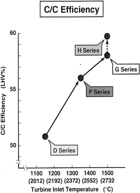
Combustor technology is shifting toward meeting single-digit NOx emissions. The changes occurring under deregulated generation and dispatch also necessitate that the NOx emission levels are met at a broader load range. Other emissions, such as CO, VOC, and particulates, also have to be minimized. The combustion control to stabilize the flame at a lean fuel-to-air ratio is one of the most important challenges for all gas turbine manufacturers.
The thermal efficiency of today’s combined-cycle power plants are much higher than conventional steam power plants. For example, a combined-cycle power plant with the F-class gas turbine having firing temperatures between 1300 and 1400°C attains thermal efficiency of 55–57%. The combined-cycle efficiency has been further improved by raising the firing temperature, as shown in Figure 14–1, and it has even reached 58–60% for the G- and H-class gas turbine.
In order to use valuable clean energy efficiently, several key technologies for efficient and environmentally benign combined-cycle power generation have been applied:
1. Dry, low NOx combustion technology
3. Heat resistant materials and casting technology
4. Aerodynamic design methodology
It has been demonstrated that the development of these key technologies for large frame gas turbines can be made economical by using the knowledge and experience acquired from aeroengine developments. However, in many cases, there are limitations in extrapolating the aeroengine technologies directly to large frame gas turbines due to size and duty cycle differences. For example, casting of large directionally solidified and single-crystal blades is much more difficult than smaller aeroengine blades. Alloy composition and heat treatment are generally altered for improving castability and production yields of the larger industrial castings. Those chemistry alterations also affect the long-term material behavior aspects. In aeroengines, the hold time exposure at peak transient stress and temperature are significantly shorter, typically around two minutes. By comparison, the LCF hold time exposure at peak stress and temperatures are several hours long in industrial applications, for peaking and base load operation. Therefore, the design approach for achieving high reliability in new high-efficiency industrial gas turbines requires retaining the proven designs features and field experience from the frame machines, while transferring aeroengine design technologies and field experience for optimizing stage efficiencies, heat rates, and output.
Design Decisions Influencing Reliability
Key features that are important from the standpoint of reliability are use of proven design structural features, maintaining same scaling procedures, use of proven materials, and extensive verification testing.
Use of Proven Design Structural Features
Figure 14–2 compares rotor cross-sections of the Mitsubishi M501D, M501F, M501G, and M501H gas turbines. There is a striking resemblance between the rotors. Except for the spool-type compressor in the M501D, the compressor and turbine sections in the F, G, and H gas turbines even maintain the exact same bolt count: 12. By retaining the proven design features in the product evolution (see Table 14–1), the design engineers continue to work within the field experience window relative to temperatures and stresses.
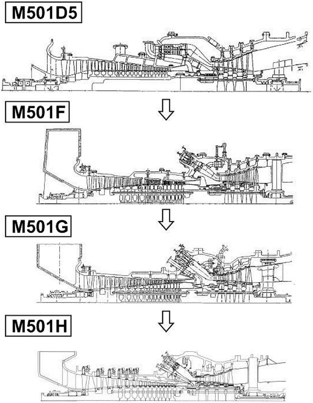
TABLE 14–1
| Feature | 501D5 | 501F | 501G | 501H |
| Cold end generator drive | ✓ | ✓ | ✓ | ✓ |
| 2-Bearing rotor | ✓ | ✓ | ✓ | ✓ |
| 4-Stage turbine | ✓ | ✓ | ✓ | ✓ |
| Individual combustors | ✓ | ✓ | ✓ | |
| Horizontal split casing | ✓ | ✓ | ✓ | ✓ |
| Single row 1 vanes | ✓ | ✓ | ✓ | ✓ |
| Cooled & filtered rotor air | ✓ | ✓ | ✓ | (Steam Cooling) |
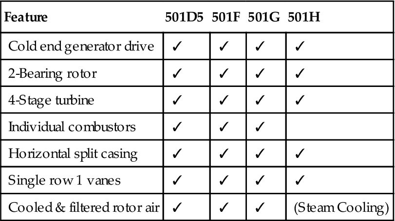
(Source: Mitsubishi Heavy Industries.)
MHI rotor designs make use of “positive torque” features for enhancing torque transmission without slippage. In fact, field experience has proven that the use of radial pins in the compressor and curvic couplings in the turbine enhance the overall resistance to interstage slippage, which is particularly important from a startup/shutdown consideration. Another necessary design feature in advanced design compressors is the provision to replace foreign object damage of compressor blades quickly on site without transporting the rotor to a service overhaul repair facility.
Maintaining Same Scaling Procedures
The scaling procedure from 60 Hz designs to 50 Hz designs has been steadfastly maintained throughout MHI product lines. For example, the first two rows of blades and vanes of the turbine are common across the 60 Hz (M501 series) and 50 Hz (M701 series) versions. Likewise, the combustors are common between the two frame sizes. The field experience and design calibration with this scaling approach is retained across MHI’s D, F, and G classes of gas turbines. By contrast, others have deviated significantly in scaling method, rotor structure, materials, and coatings.
Use of Proven Materials
Table 14–2 compares the materials used in MHI’s F-, G-, and H-class machines. The commonality in materials simplifies transfer of field repair experience and practices. Also, the use of fewer standardized materials makes it possible to concentrate on long-term material properties characterization.
TABLE 14–2
Materials Commonality Retained
| Materials used in F, G, & H | |
| MGA 1400 | Turbine blades rows 1 to 4 |
| MGA 2400 | Turbine vanes rows 1 to 3 |
| Tomilloy | Combustor transition piece |
| Low alloy steel | Rotor |
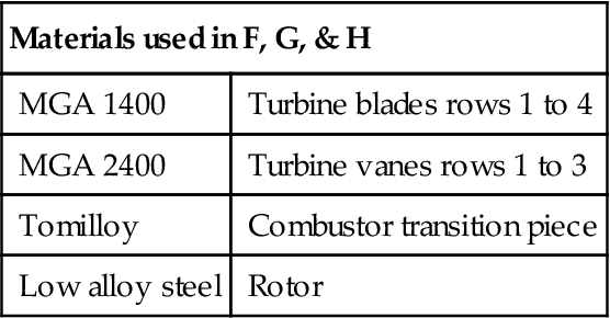
(Source: Mitsubishi Heavy Industries.)
By retaining materials and field proven structural design features, MHI’s design focus has been on improving stage efficiencies in the compressor and turbine through state-of-the-art 3D aerocomputational techniques. Figure 14–3 is a picture of the advanced 3D designed compressor blades in the H machines. The use of such advanced tools has made it possible to achieve a 25:1 pressure ratio, as compared to 20:1 with the G machine. More importantly, the higher pressure ratio is achieved with two fewer stages than the G. Thus, similar rotor spans are maintained for the G and H machines, thereby optimizing on design operating experience and reliability aspects.
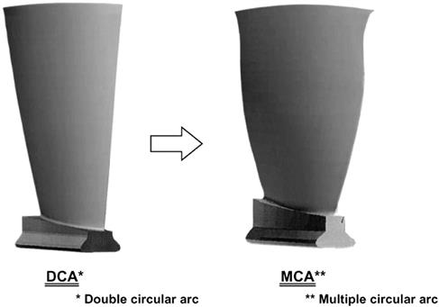
The M501 gas turbine has a 16-can dry premix low NOx combustor to satisfy the worldwide NOx emission regulations. The established concept of the premix combustor is retained, such as the two-stage burner assembly and the bypass valve system. The feature of the combustor is the application of a multiple fuel nozzle system to improve flame stability in lean burning. The combustor has a pilot nozzle in the center and eight surrounding main nozzles supplying the premixed air and fuel. Proper adjustment of fuel flow rates through the pilot and the main nozzles allows the NOx emission to be maintained at a lower level than that of its predecessor in the entire load range. The combustor wall and the transition piece are cooled using efficient double-wall cooling structures developed by Mitsubishi, named MTFIN™. The structures efficiently provide more air to the combustion region for the lean, low-NOx burning. The F-class premix combustor is shown in Figure 14–4.
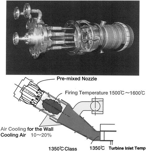
Extensive Verification Testing
Throughout MHI’s almost 40 years as an industrial gas turbine OEM, new technologies have been made commercially available only after full-scale full-load testing at MHI’s internal facilities. Figure 14–5 is a picture of a full-scale MHI combined-cycle power plant at Takasago, called T-Point facility. The facility is operated usually under daily start-stop operation, especially during the summer peak season, and power is transmitted to a local utility. Thus reliability and availability aspects have to be met according to stringent commercial contractual expectations. Thorough inspections following the peak dispatch season enable continuous validation and modifications for enhancing component durability, power plant reliability, and availability. For example, minor design adjustments made during early stages of machine verification and operation resulted in enhancements to cooling circuits, resulting in superior thermal distributions and improved material/coating performance and component durability prior to commercial introduction of G technology. MHI followed a similar approach before commercial introduction of F technology.
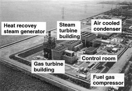
Figures 14–6 through 14–8 show the excellent condition of hardware at the fourth inspection on the M501G machine at T-Point following 10,185 hrs and 561 starts. The facility is also utilized for validating the H machine. For the previously mentioned reason, the common rotor span between the G and H machines makes it possible to use the T-point facility to conduct design validation tests at the facility.
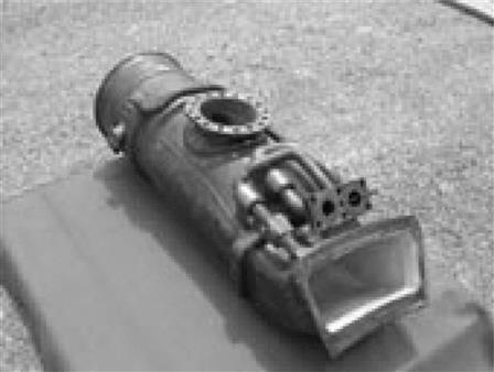
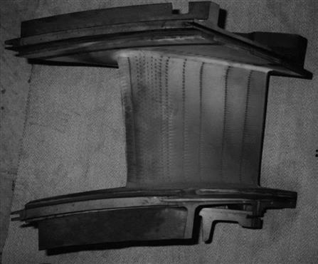
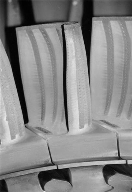
Case Study 2: How Close Is the Measured Performance to the True Output and Heat Rate? The Proof Is in the Testing!15
The huge increase in electrical power demand continues worldwide and especially in the United States. Therefore, an increasing number of existing power plants plan thermal performance tests to check their power output range (not necessarily the same as when they were commissioned), before they commit to any further power deliveries.
A thermal performance test on a new plant is a test where the end user checks that his newly commissioned plant meets the power output guarantees made by manufacturers and contractors. The proper conductance of the test, data collection, and correction to reference conditions have many contractual, technical, and commercial implications for all parties.
The practical aspects of testing, from contract negotiations to field implementation, in which the thermal evaluation of a power plant facility and its major components is carried out, are described as follows.
ASME Performance Test Codes
The American Society of Mechanical Engineers (ASME) performance test codes (PTCs) serve as the guiding documents for all aspects of performance testing. The ASME test codes have achieved worldwide acceptance and are applied in Asia, Australia, South America, and Europe.
In the last six years, to keep up with the rapid technological changes, most of the PTCs have been updated and reissued. PTC-46, Power Plant Performance Test Code (1996), is routinely implemented in combined-cycle facilities. PTC-22, Gas Turbine Performance Test Code, will expand its scope to cover the testing and calculations for exhaust temperature and exhaust flow, in addition to power output and heat rate. This new version is because the industry needs to provide guarantees for exhaust energy and exhaust temperature in combined-cycle applications. The methodology will be based on a complete mass and energy balance around the combustion turbine. A new version of PTC-6, Steam Turbine, was issued in 1996. A committee was formed in 2000 to develop a new PTC-6.2 dealing exclusively with steam turbine performance in combined cycles. A new and comprehensive Measurement Uncertainty Code, PTC-19.1, was issued in 1998. A draft for a new PTC-4.4 for heat recovery steam generators (HRSGs) was released for industry review. PTC-4.4 (HRSGs) and PTC-22 (gas turbines) are being revised in close cooperation so that they use the same methodology for calculating combustion turbine exhaust heat (input source for the HRSG). New codes in the PTC-19 series dealing with measurement techniques are close to publication, of particular interest being PTC-19.5, which covers flow measurement.
Combined-Cycle Guaranteed Values
The testing of combined-cycle power plants, including combustion turbines, HRSG, and steam turbines, requires two measurements:
• The electrical power output on the high side of the transformers
• The fuel heat input—flow and composition—at the facility fence
Accurate evaluation of the thermal performance in a power plant is challenging. Errors in measurement of power output and heat rate could translate to millions of dollars in liquidated damages (LDs). An example of the commercial risks for missing the guarantees even by very small amounts is presented in Table 14–3. A typical 800 MW power plant with a 6000 BTU/kWh heat rate could pay LDs in excess of $1 million for shortages of 0.07% in performance guarantees.
TABLE 14–3
Potential Commercial Liquidated Damages—Typical Case [14-4]
| Guarantee | Error | Error (%) | LDs | LDs | |
| Power Heat rate |
8000,000 kW 6000 BTU/kWh |
500 kW 4 kW |
0.0625 0.06667 |
$1000/kW $150,000/(BTU/kWh) |
$500,000 $600,000 |
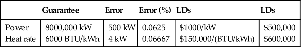
Preparations for test should start at the beginning of a project, when considering conditions and configuration. All of the parameters that might influence the test results need to be properly identified. As part of the contract definitions, all the ambient conditions at the inlet of the combustion turbine and in the vicinity of the heat sink must be stated. One must also define the location of the electrical power metering, auxiliary power measurement, power factor range, fuel quality and heating value, plant configuration during test, makeup water, and blowdown valve positions.
Test Significance
While test codes offer the basic framework, additional practical issues must be resolved to implement code recommendations in real-life situations. Most of the commercial contracts specify that test procedures must be mutually agreed on. Many end users do not realize the true aim of the thermal performance tests and combine other plant acceptance criteria with the thermal evaluation of the plant.
• The thermal performance test is not a reliability or endurance test. Very often, owners and end users request that a lengthy performance test be conducted, far beyond the recommendations of the codes. Requesting a test to be carried out for an excessive number of hours (for example, 8 or 10 hours for a combined cycle) might actually have a negative impact on the results. During these continuous runs, a wide variation in ambient temperature could result in the plant operating at conditions further away from guarantee conditions and thus cause errors.
• Thermal performance tests are used to verify the correction curves. This controversial issue is common with performance testing. In the following paragraph, the issue of correction curves will be discussed. However, plant performance guarantees are usually made for a single point. Often, the test program requires conducting several tests at different ambient conditions and plant configurations. This does not relate to the performance test but is intended to verify if the hardware behaves as correction curves predict. This is a separate task with a different objective than the performance of the equipment. So if the parties involved agree, it should be conducted before the performance test, results should be mutually accepted to by all, and correction curves should be redrawn accordingly.
• Test repeatability is not an acceptance criterion. A facility thermal performance test is a demonstration of the output and heat rate. Conducting repeated tests and comparing the corrected results might not indicate a poor test. Correction curves might be slightly different at different ambient conditions, or random error values could be higher. Verifying the instrumentation and proofing the conversion methodology are part of the pretest preparations and the mutually agreed-on test procedure, not of the test itself.
• Conformance with important design criteria of equipment. One prerequisite of the performance test procedure is to operate the power plant at base load. In most cases, there is not a clear definition of what base load means. It should be mentioned that all parties expect the equipment to perform in accordance with manufacturer’s design criteria for “safe continuous” operation. One of the most contested and difficult issues between owners, bank engineers, contractors, and manufacturers is the definition of the combustion turbine control algorithm, which is considered proprietary by the manufacturer. All of the parties need to ensure that the control algorithm used during the thermal performance test will not be further modified, which could invalidate the results.
• Conductance of the thermal performance test should not be linked to the punch list items. Arguments often arise between the parties because of the component status during the test. For example, a test can be carried out with valves or subsystems operating in manual rather than automatic mode. The performance test scope is to confirm the power output and heat rate guarantees only. As long as the safety and integrity of the equipment are maintained, the actual status of components or system, which could be fixed later as part of the punch list, should not nullify the test.
Measurement Uncertainty and Test Tolerance
The determination of the power output and the heat rate of a power plant is associated with errors in the measuring devices, corrections to guarantees, and inadequate test conductance. A rigorous measurement uncertainty analysis is now required by all PTCs to assess statistically the potential gap between the test results and the “actual true” power output and heat rate of the plant. The analysis, fully described and commented on in PIC-19.1, basically identifies systematic error (an offset from the actual value obtained by nonstatistical methods) and precision errors (random errors derived by statistical methods) of each primary variable, from the sensor to the data acquisition system.
These values are multiplied by a sensitivity coefficient quantifying how each variable influences the result of either power output or heat rate. The square root sum of squares for all parameters is calculated to determine a ± tolerance band. The area, defined by the band applied around the measured test results, creates a domain where there is a 95% confidence level that the “true power output or heat rate” could be found. An example is presented in Table 14–4, where the power output uncertainty is 0.5% and the heat rate uncertainty is 0.87%. For the same example of an 800 MW power plant, the uncertainty for power equals ±4 MW valued at $4 million, using the same LD criteria as in Table 14–3. Respectively, for a heat rate value of 6000 BTU/kWh, a 0.87% uncertainty equals ±52 BTU/kWh and has a value of $7.8 million. Thus, the commercial value of measurement uncertainty equals close to $12 million or 2.8% of the entire typical project cost.
TABLE 14–4
Typical Measurement Uncertainty for a Combined-Cycle Plant [14-4]
| Parameter | Sensitivity | Systematic Uncertainty | Systematic Uncertainty Contribution | Random Uncertainty | Random Uncertainty Contribution |
| Power Output Measurement Uncertainty | |||||
| Ambient temperature | 0.26051 %/°F | 1.33°F | 0.34648°F | 0.20780°F | 0.05413 |
| Facility net output | 1.00000 %/% | 0.258 | 0.25800 | 0.15800 | 0.15800 |
| Barometric pressure | 4.23000 %/psia | 0.039 psia | 0.16497 psia | 0.02000 psia | 0.08460 |
| Ambient RH | –0.00156 %/%RH | 2.0040 | –0.00313 | 0.50000 | –0.00078 |
| Circ. water temp. | 0.01428 %/°F | 4.170°F | 0.05955°F | 1.00000°F | 0.01428 |
| CTG shaft speed | 0.02549 %/rpm | 0.271 rpm | 0.00691 rpm | 0.50000 rpm | 0.01275 |
| CTG gross output | 0.01052 %/% | 0.318 | 0.00335 | 0.20000 | 0.00210 |
| STG gross output | 0.00389 %/% | 0.3260 | 0.00127 | 0.20000 | 0.00078 |
| CTG power factor | 0.01875 %/% | 1.030 | 0.01931 | 0.00800 | 0.00015 |
| STG power factor | 0.00490 %/% | 1.0300 | 0.00504 | 0.00800 | 0.00004 |
| RSS | 0.46674 | 0.18821 | |||
| Total uncertainty | 0.5033 | ||||
| Heat Rate Measurement Uncertainty | |||||
| Gas fuel flow | 1 %/% | 0.801°F | 0.80100 | 0.05000°F | 0.05000 |
| Gas heating value | 1 %/% | 0.150°F | 0.15000 | 0.04000 | 0.04000 |
| Ambient temperature | 0.0056 %/°F | 0.562°F | 0.00315 | 0.20780°F | 0.00116 |
| Facility net output | 1 %/% | 0.258 | 0.25800 | 0.15800 | 0.15800 |
| Barometric pressure | 0.38 %/psia | 0.0039 psia | 0.00148 | 0.02000 | 0.00760 |
| Ambient RH | 0.0023 %/%RH | 2.0000 | 0.00460 | 0.50000 | 0.40115 |
| Circ. water temp. | 0.012 %/°F | 4.170°F | 0.05004 | 1.00000 | 0.01200 |
| CTG shaft speed | 0.0024662 %/rpm | 0.271 | 0.00067 | 0.50000 | 0.00123 |
| CTG gross output | 0.011 %/% | 0.318 | 0.00350 | 0.20000 | 0.00220 |
| STG gross output | 0.0039 %/% | 0.3260 | 0.00127 | 0.20000 | 0.00078 |
| CTG power factor | 0.019 %/% | 1.030 | 0.01957 | 0.00800 | 0.00015 |
| STG power factor | 0.0049 %/% | 1.0300 | 0.00505 | 0.00800 | 0.00004 |
| RSS | 0.85657 | 0.17110 | |||
| Total uncertainty | 0.87344 | ||||
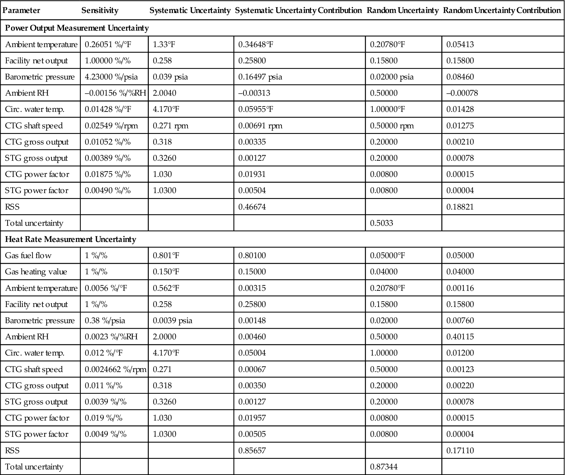
Correction Curves
Power plants are rarely tested at the guaranteed conditions (which usually includes ambient conditions, generator power factor, and other specific plant configuration requirements, such as blowdown). To demonstrate if a test has achieved the guaranteed power output and heat rate, a well-established methodology of correction curves is applied. A correction curve for a specific parameter, for example, ambient temperature, is developed using a computer simulation program, where all of the other variables are kept constant at their guaranteed conditions. Only the parameter in question is allowed to vary, and the impact on power output and heat rate is recorded. A curve is drawn, showing the variation of the power output versus ambient temperature, as shown in the example in Figure 14–9. The curve is then converted to a polynomial equation and further used with other correction curves in a large spreadsheet. The entire process is tedious, time consuming, and expensive.

There are many significant problems with this methodology, which could very significantly skew the test results.
As can be seen from Table 14–5, the use of correction curves started with the simple process of a single homogeneous fluid expansion, which could be depicted quite accurately. As the concept is expanded to more than one thermodynamic process, the correction curves become two and three dimensional.
TABLE 14–5
Thermodynamic Processes [14-4]
| Component to be Tested | Type of Thermodynamic Process | Comments |
| Steam turbine | Adiabatic expansion | Single homogeneous fluid |
| Combustion turbine | Adiabatic compression | Air |
| Combustion | Fuel and air | |
| Adiabatic expansion | Exhaust gases | |
| HRSG | Heat transfer | Steam and exhaust gases |
| Vaporization | ||
| Heat sink | Condensation | Steam |
| Various heat removal methods using phase change | Water and air | |
| Combined cycles | All of the above | |
| All of the above | ||
| Integrated gasification combined cycle (IGCC) | Gasifier Air separation unit |
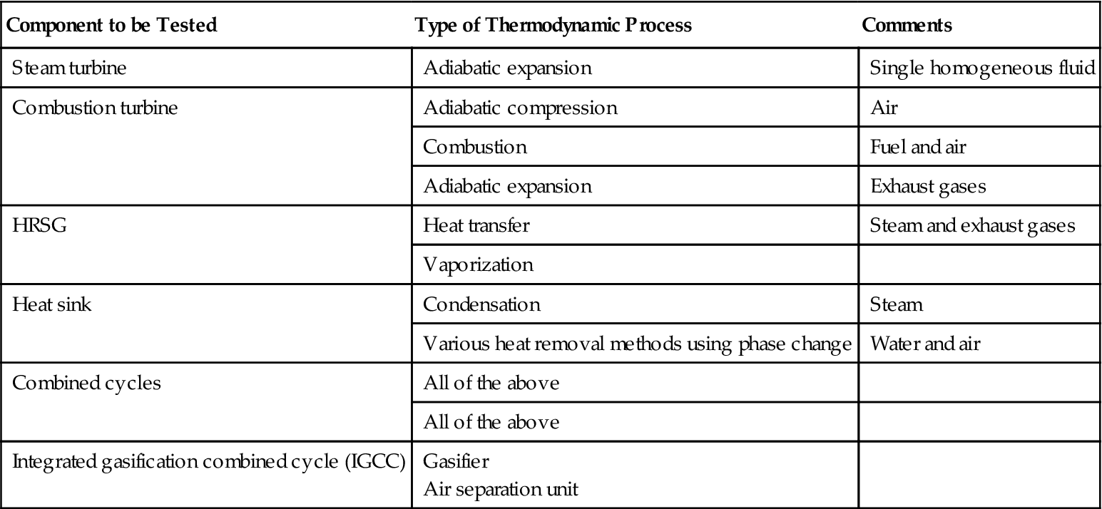
An alternative solution to the problem is to apply a complete computer simulation program for the plant behavior. Thus, all variables can be adjusted simultaneously and all the basic laws for mass, momentum, and energy balance are truly maintained. The correction curve methodology cannot account for secondary effects on the turbomachinery because of the coupled effect of changes in more than one variable. Ambient temperature and relative humidity are the most common examples.
Degradation Curves
The final thermal performance tests of a combined-cycle plant are conducted after all of the components—combustion turbine, HRSG, and steam turbine—are commissioned and fine-tuned, a process that requires a significant number of hours of operation for each of the components. To cover the gap from the “new and clean” performance guaranteed by the manufacturer to the performance measured during the test, equipment degradation curves have been used.
The most influential degradation curve is associated with nonrecoverable degradation of the combustion turbine performance. The combustion turbine manufacturer produces these curves based on the results of the performance fleet and in-house evaluation. Great significance is attached to the shape of the curves for obvious impact on plant performance.
Particularly for new models where fleet experience is not totally applicable, conservative degradation curves are used. Attempts to develop specific curves based on actual tests are extremely difficult because changes in performance for small numbers of operating hours are the same order of magnitude as the measurement uncertainty.
Inlet Cooling Devices
Inlet cooling devices are a safe and profitable means to achieve better performance at low risk and low cost. Evaporative cooling, inlet fogging, inlet air refrigeration using mechanical compression, and absorption systems are popular options. This has created new challenges for testing staff. The performance of the combustion turbine, and the Rankine cycle components, depends not on ambient conditions at the fitter house but on those at the inlet belmouth of the compressor. The methodology to assess the conditions at this particular plane is far more difficult and can create errors for the overall power output and heat rate values.
So is the inlet cooling device an integral part of the power plant? With mechanical chillers, should we include the entire refrigeration unit as part of the power plant?
Manufacturers have created a system of interstage cooling for aeroderivatives. How should we deal with performance testing and corrections under these conditions? Of particular concern is the use of inlet foggers with a water injection amount beyond the 100% relative humidity, commercially called wet compression.
So some recommend that one exclude all the inlet or interstage cooling devices from the applicable control volume of the power plant. Particularly for combustion turbine tests, verification of the guaranteed exhaust flow and exhaust temperature is almost impossible when the inlet-cooling device is running. However, one can conduct tests with the inlet cooling on and then off for comparison purposes.
Case Study 3: Comparative Evaluation of Power Plants with Regard to Technical, Ecological and Economical Aspects16
The final evaluation of power generation technologies is based mainly on its electricity generation costs or life cycle cost. Considering today’s fuel prices and price development projections over the plant lifetimes, the economical analysis performed can serve as a framework for project and investment decisions.
More stringent environmental regulations raise production cost. Long-term planning in power plant capacities has become uncertain as never before. Changing fuel prices are the third parameter that has to be considered before investing in power plants. According to forecasts of the world energy conference and others, the fossil fuels, like coal, oil, and natural gas, will be also in the near future our main energy source for power generation (Figure 14–10).
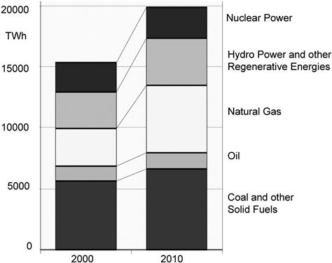
Therefore it is very important to use these nonrenewable energies with great care and burn them only in highly efficient plants. This saves not only our limited reserves but also cuts emissions in order to protect life, environment, and climatic stability.
An overview follows of state-of-the art and future power plant technologies, environmental issues, cost, and economic considerations. We employ the following abbreviations:
PC = Pulverized coal steam power plant
AFBC = Atmospheric fluidized bed combustion
IGCC = Integrated gasification combined cycle
ACFBC = Atmospheric circulating fluidized combustion bed
Available Technologies
Considering the time frame up to the year 2005, no revolutionary new power plant technology will be commercially available. The improvement will be found mainly in higher efficiencies due to enhancement of components and an increase in the upper process temperatures of the well-known processes. For all plant designs, the same boundary conditions have been assumed unless otherwise stated, which are in Table 14–6.
TABLE 14–6
Assumed Boundary Conditions [14-5]
| Ambient temperature | °C/°F | 15/59 |
| Ambient air moisture | % | 60 |
| Ambient air pressure | bar/psi | 1013/14.69 |
| Condenser pressure | mbar/psi | 50/0.725 |
| NOx emission | mg/m3 STP | 150 |
| SOx emission | mg/m3 STP | 100 |
| Dust emission | mg/m3 STP | 50 |
Coal-Fired Power Plants
Due to large reserves and the worldwide availability of coal, both lignite and hard coal, this energy carrier also will play an important role for electricity generation in the future. Although the increase in consumption will be lower than that of natural gas, the relative contribution to the total electricity production will still amount to approximately 33–34%. Therefore, investment in the development of coal technologies also will be of great importance in the future.
Pulverized Coal Power Plants
Today’s atmospheric pulverized coal power plants (Figure 14–11) are characterized by high efficiencies, high availability, and high reliability. They serve a power range from 20–1000 MW per block, whereas the lower capacities up to 300 MW are usually built as atmospheric fluidized bed combustion systems. For large grids, large-sized double units are preferred for cost reasons.
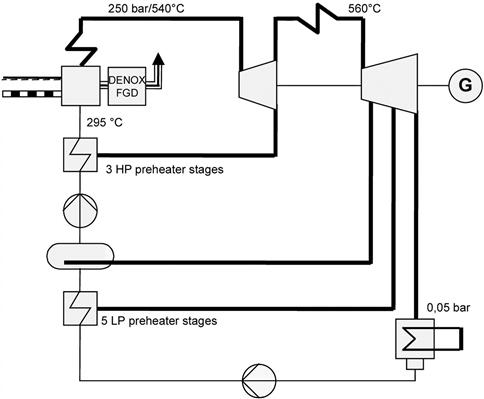
The design points out that net efficiencies for a modern power plant with wet cooling towers and secondary measures for flue gas cleaning can be well above 40% LHV. Due to startup losses and partial load operation, the mean annual net efficiency can be lowered, however, by up to 3 percentage points. For these investigations, only the design points have been considered.
In industrialized countries, newly built large power plants usually have steam conditions of 250 bar and 540°C and are equipped with reheat. In a few cases, power plants with steam conditions of 285 bar and 600°C are under construction. The influence of the steam parameters on the efficiency and investment is shown in Figure 14–12. From this diagram, it can be seen that the investment is increasing more than proportionally compared to the efficiency increase.
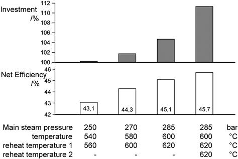
With the help of desulfurization plants (FGD), DENOX, and dust filters, all the emission limits set up by any regulation authority can be met easily. The limits applied in this study (see Table 14–6) are more stringent than any current limits in the world, but they are expected to be relevant in future power plants.
Pressurized Fluidized Bed Power Plant
The power plant with stationary pressurized fluidized bed combustion (PFBC) was introduced into the market in the 1990s. Since then, seven plants have been built and a cumulated operating experience of more than 100,000 hours could be gained. While the first plants had a capacity of only 70 MW, in Japan the first plant with an electrical output of 350 MW is in the test phase.
The advantage of this type of plant is its possibility to reduce the sulfur and nitrogen emissions only by primary measures, thus saving investment for secondary measures. In addition, this plant can be fed a very wide range of coal types with different compositions. Due to the low operating temperature in the steam generator of approximately 850°C, the formation of thermal NOx can be kept at a minimum. The reduction of SOx is being managed by adding limestone directly into the fuel, where it is reacting with the sulfur and bonded in the ash. The degree of reduction can be adjusted by the sulfur/limestone ratio. As long as today’s emission standards are applied, the limit values can be maintained, but for lower values, secondary measures, at least for NOx, have to be taken, such as the SCR installed with the 350 MW Karita plant in Japan. This, however, reduces the cost advantage of this concept.
By means of expansion of the exhaust of the supercharged steam generator (12–18 bar) in a bottoming gas turbine, the high temperature also can be used for power generation and hence reducing exergetic losses. The gas turbine drives the compressor for the combustion air and in addition an electric generator, which produces about 20% of the total power output. In this way, a net efficiency of approximately 42% LHV can be reached.
An improvement of the efficiency by increasing the process temperature is not possible because of the ash melting point. Higher temperatures would make it impossible to reduce the ash content in the flue gas by cyclones, which are needed to protect the bottoming gas turbine against erosion.
Because of the limitation of temperature, this concept cannot take advantage of the highly efficient modern gas turbines with high inlet temperatures. Therefore, the so-called second generation circulating pressurized fluidized bed combustion (Figure 14–13) is being developed.
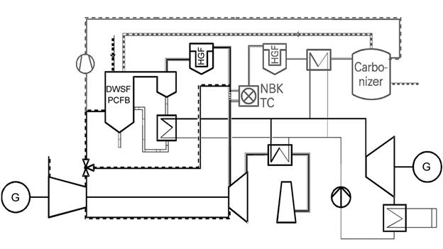
Its higher thermal power density enables very high efficiencies of above 50% LHV. This concept consists of a circulating pressurized fluidized bed combustor (CPFBC) with a pressurized partial gasifier in parallel that generates a syngas. The gasifier converts only 60–80% of the carbon, and the rest is burned completely in the CPFBC. After cleaning the flue gas from particles in two filter stages, its temperature can be raised to gas turbine inlet temperature by means of the syngas of the gasifier. The exhaust gas of the gas turbine can be utilized in a steam process in the same way as it is done in a conventional combined-cycle plant.
To maintain today’s emission standards, an adequate sulfur bonding can be reached by admixing additives into the fuel. Because of the high process temperature, an SCR plant for NOx reduction will be necessary.
This concept is still under development, and it has to be demonstrated that the particles in the flue gas can be kept below the permissible values of the gas turbine.
Integrated Coal Gasification Combined Cycle
The concept of an integrated gasification combined-cycle plant incorporates an oxygen or air-blown gasifier operating at high pressure and producing raw gas, which is cleaned of most pollutants and burned in the combustion chamber of the gas turbine (Figure 14–14). The sensible heat of the raw gas and the hot exhaust gas of the gas turbine are used to generate steam, which is expanded in a steam turbine. The mechanical energy of the gas turbine as well as the steam turbine is used to produce electric power.
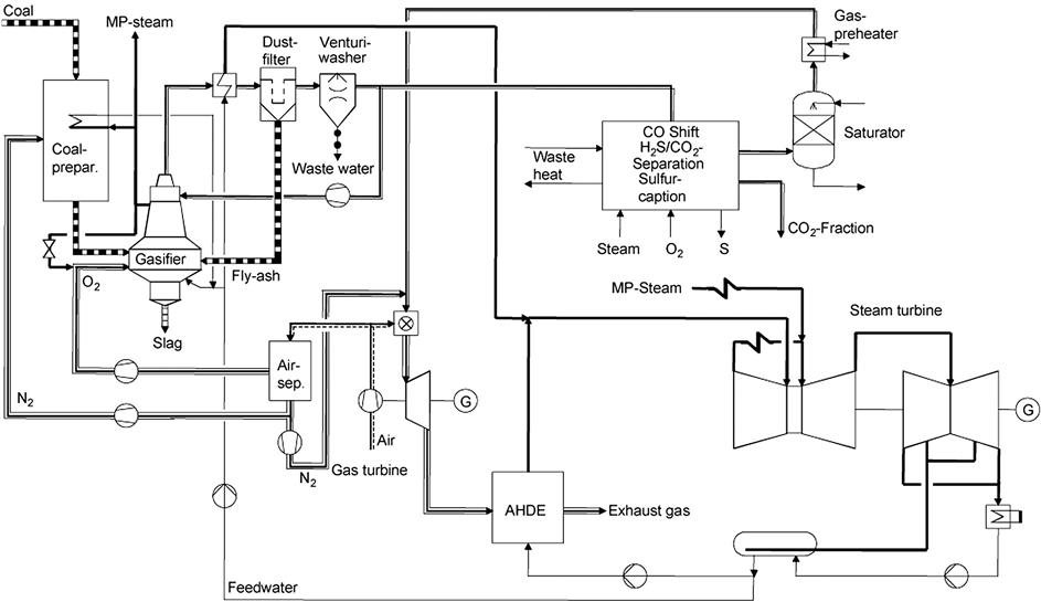
While the power plant systems are well known and commercially available, the different gasification processes, including their auxiliary systems, are still at the beginning of commercial-scale production.
The potential of a high net efficiency of more than 50% LHV and very low sulfur and dust emissions—they are removed before passing the combustion process—make it an attractive option for future power generation.
Until 1998, five demonstration plants for coal gasification with outputs of between 100 and 300 MW have been put into operation worldwide.
Gas-Fired Power Plants
Because of the quick gas turbine development, driven by strong competition, during the past 10 years, the conventional gas-fired steam plants are no more of interest. This is not only due to their relatively low efficiency but also due to their relatively high investment.
The outstanding performance of natural gas-fired combined-cycle (CC) plants (Figure 14–15) has led to the situation in which many of the old conventional power plants have been shut down in favor of new CC plants.
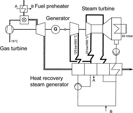
These CC plants are available in a wide power range from 50 MW up to 800 MW per block. The large units reach a net efficiency level of approximately 56–58% today. Even the small plants rated at about 100 MW are still well above 50%. New plants, which are already under development and in construction, are supposed to reach the target value of 60% by the year 2002.
Besides high efficiencies, combined-cycle plants are characterized by low investment, low service cost, and outstanding environmental behavior. The only negative aspect in the row of benefits is the availability of the gas and the gas price, which is very sensitive to market alterations.
Efficiencies
The comparison of efficiencies (Figure 14–16) shows that the whole range of modern base-load power plants is able to reach a net efficiency of more than 40%. The outstanding performance of the combined-cycle plants is not only due to its technology but also a result of the use of a high-valued clean fuel.
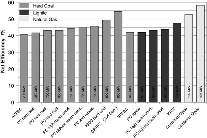
The conventional coal-fired steam power plants have only a limited potential in increasing its efficiency by raising the steam parameters or adding a second reheat stage.
Only the new technologies like IGCC and CPFBC are able to overcome the limitations that restrict conventional steam turbine cycles. These technologies, such as the natural-gas-fired CC plants, use a combination of gas turbine and steam turbine and hence are able to use the entire temperature gradient from the combustion chamber.
These technologies are very attractive since they run on almost any type of coal, which is the longest lasting fossil fuel source.
Emissions
The consciousness of a benign environment is more and more important to the people all over the world. Power plants are besides the traffic the branch with the highest output of gaseous emissions. Several ecological anomalies, like acid rain, the greenhouse effect, and overheating of rivers, can be attributed to power plants.
In the meantime, government and industry in many countries have been responding with emission regulations and the positive results can be seen already in many areas. Basically all emissions are reduced by increasing plant efficiency. That means less fuel is required to generate the same amount of electricity and thus also less pollution is efficient. But this is not enough, and other measures have to be taken to limit the amount of pollutants.
Dust filters are now standard equipment in many of the power plants all over the world, admittedly with differing limit values. Certainly, a lot more can be done for a cleaner environment.
The reduction of SOx and NOx is technically somewhat more complicated and more costly. Therefore, only industrialized countries have been ready so far to invest in these technologies. Flue gas desulfurization plants and DeNOx plants are state of the art and enough experience exists for reliable operation without too much influence on the power plant performance. A reduction down to a concentration of 100 mg of SOx or NOx per m3 of flue gas with secondary measures is easily achievable.
Fluidized bed combustion systems are able to reduce SOx by primary measures only down to approximately 150 mg/m3 STP by means of adding dolomite directly into the coal feed where it reacts with the sulfur to form CaSO4 (gypsum), with the result that no further bonding agent is required for the ash product to set when water is added. Due to the low combustion temperature of approximately 850°C in FBC systems, the formation of thermal NOx can be avoided right on the spot. This leads to NOx emissions of only approximately 150 mg/m3 STP, eliminating the need for secondary equipment. Only the CPFBC needs an SCR system, because it makes use of the advanced gas turbines with high inlet temperatures.
The desulfurization process in gasification systems is the most effective one, because the sulfur is captured already in the raw gas of the gasifier, where elemental sulfur, a saleable product, can be produced.
The use of the clean fuel “natural gas” in the combined cycle results neither in SO2 output nor in any output of waste.
To make the different power plant technologies comparable regarding their main pollutants and wastes, shown in Figures 14–17 and 14–18, the various pollutants are related to 1 kWh of electricity output.
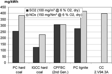
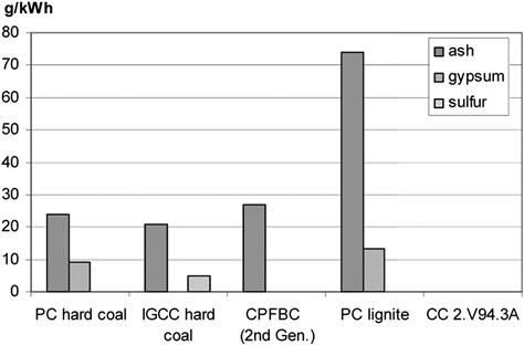
The emission of the greenhouse gas CO2 from power plants is dependent on the type of fuel and the efficiency (Figure 14–19). The capture of CO2 is technically feasible and there are even solutions for the long-term deposit of the CO2, such as in the oceans or in depleted oil fields, but economical reasons make a realization of these ideas today impossible.
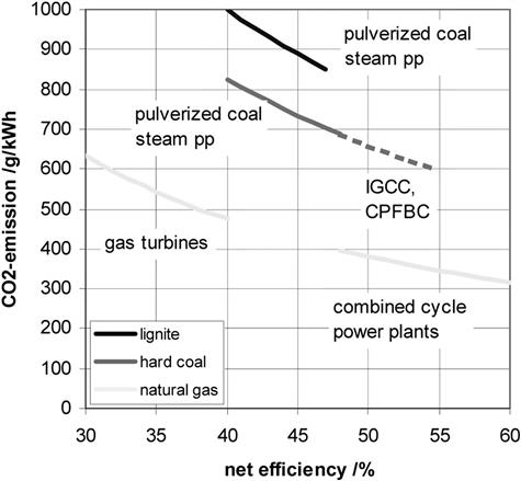
Power Plant Investment
Figure 14–20 shows 18 power plant concepts classified according to fuel type. For the pulverized-coal-fired power plants both the influence on capacity size and the additional cost for higher steam parameters are given. All costs include the necessary environmental equipment to reach the standard as specified in Table 14–6.
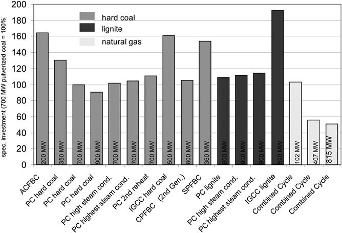
The cost data specified for the emerging technologies have to be understood as target costs for the coming years, when enough design experience exists to cut costs considerably. Their cost accuracy can be assumed to be within 15–20%.
The investment for lignite-fired power plants is approximately 20 percentage points above that of hard-coal-fired power plants because of the larger steam generator and the higher expenditure for coal feed and ash removal systems. Because of the low BTU fuel, which would cause very high transportation cost, these plants are usually built as mine-mouth plants.
The natural-gas-fired combined-cycle plants are attractive not only because of their outstanding high efficiency but also by their very low investment, which is only about 40% of a hard-coal-fired power plant. But one never should forget that it consumes only high-priced, noble fuels, such as natural gas or light fuel oil with limited reserves.
Economic Evaluation
Besides the plant investment, the fuel price is the most influential portion of electricity generation cost. Furthermore, the fuel price can be subject to relatively large changes over time. Therefore it is the most critical factor for long-term planning.
For this study the fuel prices according to Table 14–7 have been assumed, which represents an estimation of average prices in Europe.
TABLE 14–7
| Prices as of Year | Fuel Price | Price Increase | |
| EUR/GJ | $/MMBTU | %/a (real) | |
| Hard coal | 1.3 | 1.3 | 0.5 |
| Lignite | 1.5 | 1.5 | 0.0 |
| Natural gas | 3.1 | 3.2 | 1.0 |
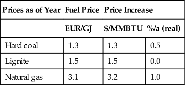
Selections of additional important boundary conditions that have been used for the economic evaluation are given in Table 14–8. Operation and maintenance costs have been assumed individually for each plant.
TABLE 14–8
Economic Boundary Conditions [14-5]
| Price basis | Year | 2000 |
| Start of operation | Year | 2005 |
| Interest rate | %/a | 8 |
| Depreciation period | a | 15 |
| Full-load operating hours | h/a | 7000 |
The resulting power generation costs show clearly the advantage of the natural gas-driven combined-cycle plants. Only the pulverized-coal-fired plant of high capacity can compete with them. The “second generation” circulating pressurized FBC plant is in the same cost range, but this plant has to prove whether the assumed low investment can be reached after successful market introduction. All these plants come out with lower generation costs than the pulverized-coal-fired reference plant of the 600 MW class and moderate steam conditions (Figure 14–21). Evidently, on the basis of the low coal price, advanced steam conditions do not justify their higher investment. Also lignite-fired power plants, generally of higher investment costs compared to hard coal power plants, come out with 12% higher generation cost than the reference plant. A price increase of natural gas of only 13% equals the generation costs of the reference coal power plant and the CC plant.
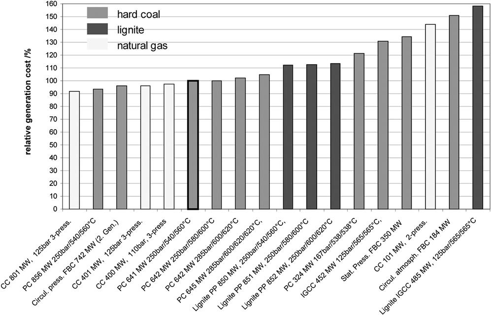
IGCC plants as well as pressurized FBC plants with their relatively high efficiency do not appear economical at today’s low coal prices.
Power generation in small capacity power plants (100–200 MW) result in approximately 40–50% higher generation costs.