
Gas Turbines
An Introduction and Applications
Abstract
The gas turbine is the most versatile item of turbomachinery today. It can be used in several different modes in critical industries such as power generation, oil and gas, process plants, aviation, as well domestic and smaller related industries. A gas turbine essentially brings together air that it compresses in its compressor module, and fuel, which are then ignited. Resulting gases are expanded through a turbine. That turbine’s shaft continues to rotate and drive the compressor, which is on the same shaft, and operation continues. A separate starter unit is used to provide the first rotor motion until the turbine’s rotation is up to design speed and can keep the entire unit running. The compressor module, combustor module, and turbine module connected by one or more shafts are collectively called the gas generator. The first half of this chapter looks at some typical examples of land, air, and sea use. The second half of this chapter deals in more detail with different applications and their subdivisions.
Keywords
Gas turbine; turbomachinery; oil and gas process plants; gases; land; air; sea applications; shaft power
“The farther backwards you can look, the farther forward you are likely to see.”
—Winston Churchill
The gas turbine is the most versatile item of turbomachinery today. It can be used in several different modes in critical industries such as power generation, oil and gas, process plants, aviation, as well domestic and smaller related industries.
A gas turbine essentially brings together air that it compresses in its compressor module, and fuel, which are then ignited. Resulting gases are expanded through a turbine. That turbine’s shaft continues to rotate and drive the compressor, which is on the same shaft, and operation continues. A separate starter unit is used to provide the first rotor motion until the turbine’s rotation is up to design speed and can keep the entire unit running. The relationship between pressure, volume and temperature is discussed later in this chapter. Note that this relationship is common to gas turbines regardless of the application.
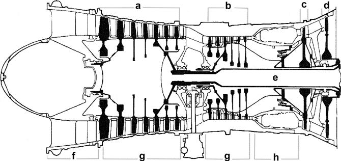
The compressor module, combustor module, and turbine module connected by one or more shafts are collectively called the gas generator. Figure 1–1 illustrates a typical gas generator in schematic format.
The second half of this chapter will deal in more detail with different applications and their subdivisions. At this time, we will look at some typical examples of land, air, and sea use.
Gas Turbines on Land
The gas turbine itself operates essentially in the same manner, regardless of whether it is on land, in the air, or at sea. However, the operating environment and criticality of the application in question may make design and system modifications necessary. For instance, the gas generator shown in Figure 1–1 may be operating in mechanical drive service to drive compressors that move gas down a pipeline. Essentially the same machine can be used to generate power. It can also be used as a power plant on an aircraft. However, the layout, the other turbomachinery supplied with the gas turbine, and optional systems will vary in each case.
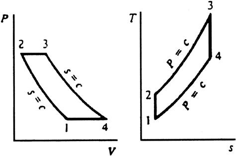
Let us first look at the basic gas turbine cycle (see Figure 1–2).
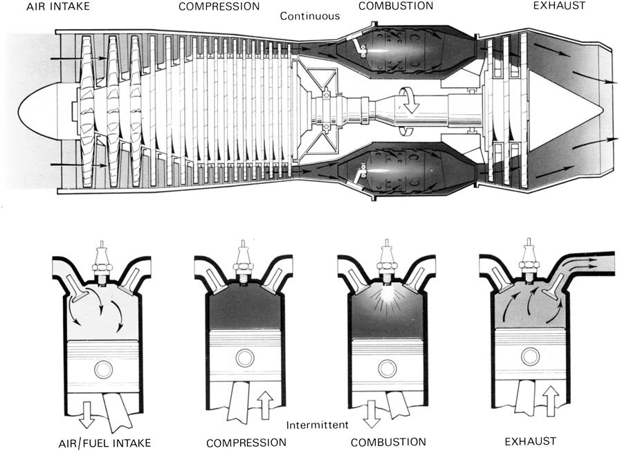
A comparison can be drawn between the gas turbine’s operating principle and a car engine’s (see Figure 1–3). A car operates with a piston engine (reciprocating motion) and typically handles much smaller volumes than a conventional gas turbine.
Direct Drive and Mechanical Drive
With land-based industries, gas turbines can be used in either direct drive or mechanical drive application.
With power generation, the gas turbine shaft is coupled to the generator shaft, either directly or via a gearbox: “direct drive” application. A gearbox is necessary in applications where the manufacturer offers the package for both 60 and 50 cycle (Hertz, Hz) applications. The gearbox will use roughly 2% of the power developed by the turbine in these cases.
Power generation applications extend to offshore platform use. Minimizing weight is a major consideration for this service and the gas turbines used are generally “aeroderivatives” (derived from lighter gas turbines developed for aircraft use).
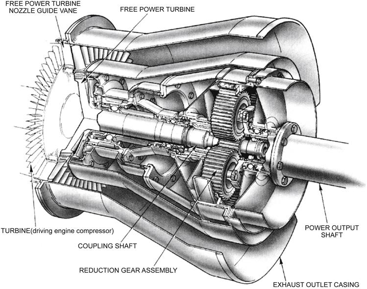
For mechanical drive applications, the turbine module arrangement is different. In these cases, the combination of compressor module, combustor module, and turbine module is termed the gas generator. Beyond the turbine end of the gas generator is a freely rotating turbine. It may be one or more stages. It is not mechanically connected to the gas generator, but instead is mechanically coupled, sometimes via a gearbox, to the equipment it is driving. Compressors and pumps are among the potential “driven” turbomachinery items (see Figure 1–4).
In power generation applications, a gas turbine’s power/size is measured by the power it develops in a generator (units watts, kilowatts, megawatts). In mechanical drive applications, the gas turbine’s power is measured in horsepower (HP), which is the torque developed multiplied by the turbine’s rotational speed.
In aircraft engine applications, if the turbine is driving a rotor (helicopter) or propeller (turboprop aircraft), then its power is measured in horsepower. This means that the torque transmission from the gas turbine shaft is, in principle, a variation of mechanical drive application. If an aircraft gas turbine engine operates in turbothrust or ramjet mode (i.e., the gas turbine expels its exhaust gases and the thrust of that expulsion propels the aircraft forward), its power is measured in pounds of thrust. The following are examples of operational specifications for land-based gas turbines.
Applications Versatility with Land-Based Gas Turbines
The gas turbine’s operational mode gives it unique size adaptation potential. The largest gas turbines today are over 200 MW (megawatts), which then places gas turbines in an applications category that until recently only steam turbines had owned.
The smallest gas turbines are microturbines. The smallest commercially available microturbines are frequently used in small power generation (distributed power) applications and can be as small as 50 kW (kilowatts). Work continues on developing microturbines that will be thumbnail size. The world of “personal turbines” where one might plug this turbine into a “drive slot” in their car, come home from work and plug it into a “household slot” for all one’s household power is a discernible, if as yet unpredictable, target.
Understanding the gas turbine’s historical origins and other applications gives the gas turbine community a better handle on optimized design, operation, and maintenance. Gas turbines came into their own in the Second World War. In peacetime, NASA took over the research that led to better alloys, components, and design techniques. This technology was then handed down to military aviation, then commercial aviation.
However, the same manufacturers generally also make gas turbines for land and marine use. So “aeroderivative” gas turbines were a natural offshoot of their flying forerunners.
Aeroderivative gas turbines are essentially aviation gas turbines that are installed on a light frame on a flat surface (ground-based, marine craft, or offshore platform). Aeroderivatives are commonly used in power generation service, particularly where a relatively light package is required, such as in offshore service.
The Rolls Royce Spey and Olympus engines, for instance, are both aeroengines but are also popular when packaged as aeroderivatives in land-based and offshore platform service.
Pratt and Whitney’s (PW) JT-8D was once the largest aircraft engine family in existence. The engine first made its appearance in the 1950s and delivered about 10,000 pounds of thrust even then. Several variations on the basic core produced a version that delivered roughly 20,000 pounds of thrust about twenty years later. This incremental power development around the same basic design saves on development costs, spares stocking costs, and maintenance. PW’s FT-8D is their aeroderivative equivalent used in both power generation and mechanical drive application.
Alstom’s GT 24/GT 26 (188 MW 60 Hz, 281 MW 50 Hz). Both Used in Simple Cycle, Combined Cycle, and Other Cogen Applications
| GT24 (ISO 2314;1989) | |
| Fuel | Natural gas |
| Frequency | 60 Hz |
| Gross electrical output | 187.7 MW∗ |
| Gross electrical efficiency | 36.9% |
| Gross heat rate | 9251 Btu/kWh |
| Turbine speed | 3600 rpm |
| Compressor pressure ratio | 32:1 |
| Exhaust gas flow | 445 kg/s |
| Exhaust gas temperature | 612°C |
| NOx emissions (corr. to 15% O2, dry) | <25 vppm |
| GT26 (ISO 2314;1989) | |
| Fuel | Natural gas |
| Frequency | 50 Hz |
| Gross electrical output | 281 MW∗ |
| Gross electrical efficiency | 38.3% |
| Gross heat rate | 8910 Btu/kWh |
| Turbine speed | 3000 rpm |
| Compressor pressure ratio | 32:1 |
| Exhaust gas flow | 632 kg/s |
| Exhaust gas temperature | 615°C |
| NOx emissions (corr. to 15% O2, dry) | <25 vppm |
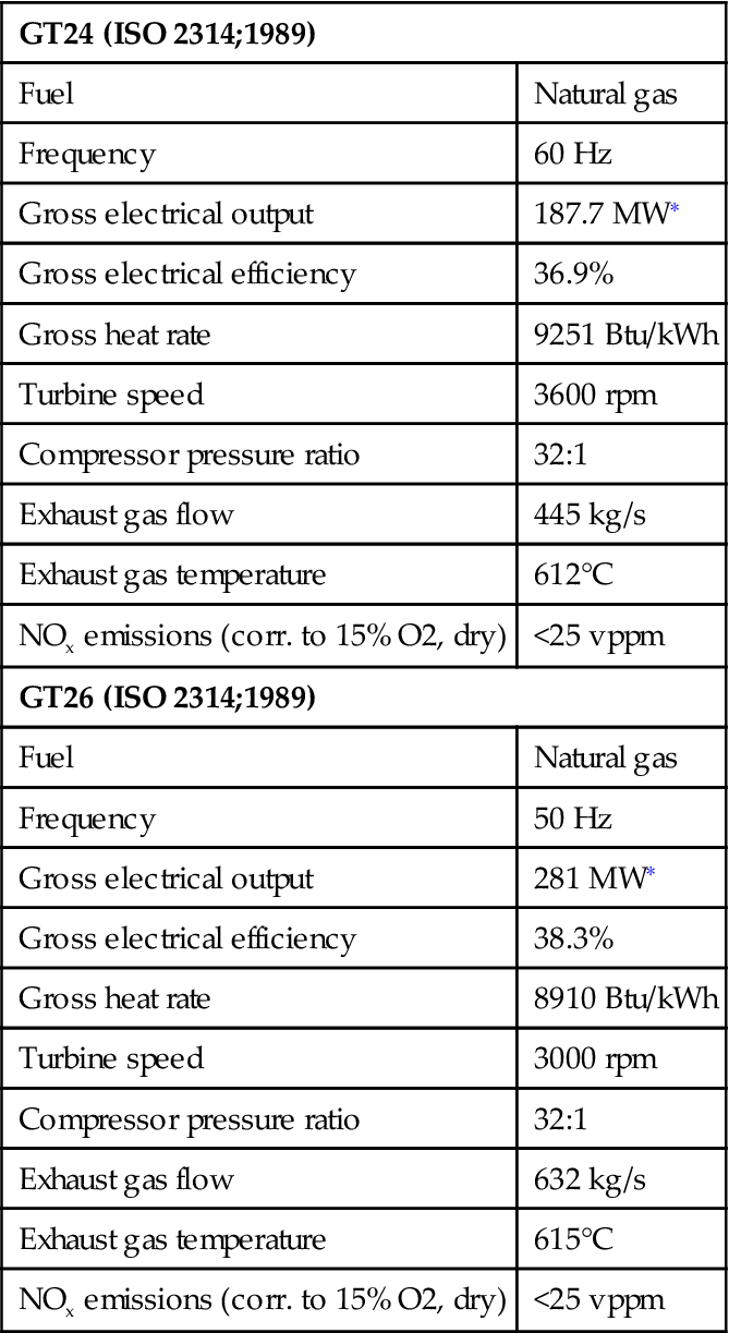
∗In a combined cycle, approximately 12 MW (GT26) or 10 MW (GT24) is indirectly produced via the steam turbine through heat released in the gas turbine cooling air coolers into the water steam cycle.
(Source: Alstom Power.)
Alstom’s GT 11N2, Either 60 Hz or 50 Hz (with a gearbox). Used in Simple Cycle, Combined Cycle, and Other Cogeneration Applications
| GT11N2 (50Hz) | |
| Fuel | Natural gas |
| Frequency | 50 Hz |
| Gross electrical output | 113.6 MW |
| Gross electrical efficiency | 33.1% |
| Gross heat rate | 10,305 Btu/kWh |
| Turbine speed | 3600 rpm |
| Compressor pressure ratio | 15.5:1 |
| Exhaust gas flow | 399 kg/s |
| Exhaust gas temperature | 531°C |
| NOx emissions (corr. to 15% O2, dry) | <25 vppm |
| GT11N2 (60Hz) | |
| Fuel | Natural gas |
| Frequency | 60 Hz |
| Gross electrical output | 115.4 MW |
| Gross electrical efficiency | 33.6% |
| Gross heat rate | 10,150 Btu/kWh |
| Turbine speed | 3600 rpm |
| Compressor pressure ratio | 15.5; 1 |
| Exhaust gas flow | 399 kg/s |
| Exhaust gas temperature | 531°C |
| NOx emissions (corr. to 15% O2, dry) | <25 vppm |
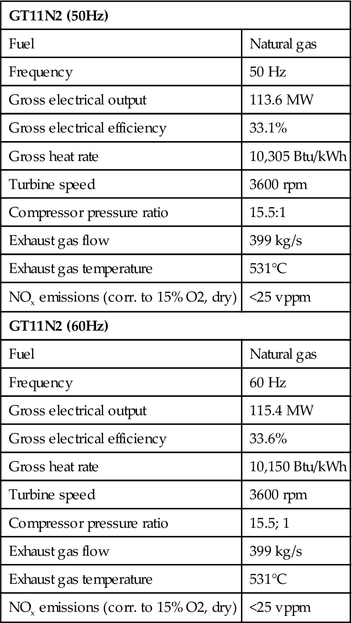
(Source: Alstom Power.)
SGT-600 Industrial Gas Turbine—25 MW (Former Designation, Alstom’s GT10)
| Technical specifications: | |
| Dual fuel | Natural gas and liquid |
| Frequency | 50/60 Hz |
| Electrical output | 24.8 MW |
| Electrical efficiency | 34.2% |
| Heat rate | 10,535 kJ/kWh |
| Turbine speed | 7700 rpm |
| Compressor pressure ratio | 14.0:1 |
| Exhaust gas flow | 80.4 kg/s |
| Exhaust gas temperature | 543°C |
| NOx emissions (corr. to 15% O2, dry) | <25 vppm |
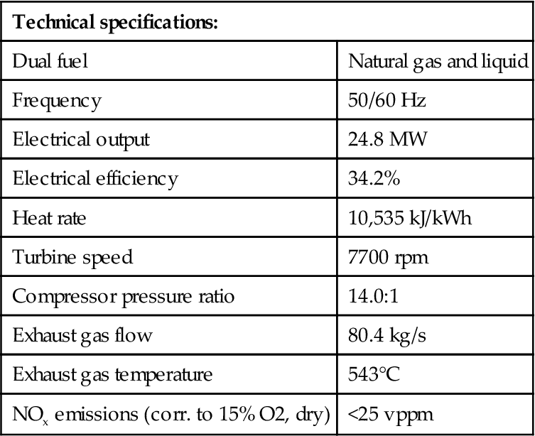
(Source: Siemens Westinghouse.)
Similarly, General Electric’s (GE’s) LM2500 and LM6000 family (aeroderivative) are essentially CF6-80C2 aeroengines that have been adapted for land-based use. What was ABB’s GT35 (land-based), then Alstom’s GT35 (change of corporate ownership), then Siemens Westinghouse’s SGT500 (yet another corporate purchase) is another example of an aeroderivative. Most aeroderivatives can also be used in marine (ferry, ship) applications. Some of them are also used on mobile land applications, such as in military tanks.
Aero- and aeroderivative gas turbine engines are likely to be built in modular construction. This means that one module of the gas turbine engine may be removed from service and the other modules left in place. A substitute module may be inserted in place of the removed module so the gas turbine can resume service. An industrial engine is more likely to be constructed in a non-modular format. If part of an industrial engine has serious problems, it is likely that the entire engine will be “down for maintenance.”
The term “industrial” gas turbine implies a heavier frame and a gas turbine model that was not intended for service where the mass (weight) to power ratio (in other words, weight minimization for the power plant) was of paramount concern. That said, the metallurgical selections for contemporary industrials reflect the best developments in metallurgical selections. The gas turbine field is a highly competitive one, and the highest turbine inlet temperatures (TITs) that can be tolerated by the metallurgical and fuel selections are sought, as this optimizes the gas turbine’s peak power rating. In other words, GE’s industrial Frame 7s and 9s (be they “-F”, “-G”, or “-H” technology) may incorporate similar metallurgy to that used on their aircraft engines. The letters F, G, and H refer to temperature ceilings and therefore imply higher power (with “later” alphabet letters).
Some turbine model designations can appear confusing in terms of their corporate ownership. This is partly due to the fact that the OEM (original equipment manufacturer) gas turbine scene changes constantly with corporate mergers, partial mergers, buyouts of specific divisions, and joint ventures. This section and the one on combined cycles therefore have several notes about specific engines’ model designation history and previous ownership. This has considerable relevance when it comes to noting the finer points of any gas turbine’s design. This is critical to operators as they can then make better decisions regarding the overhaul, performance optimization, component updates, and retrofit systems on their turbine systems.
Any Application of a Gas Turbine could have a Great Deal to Offer End-Users in other Industrial Sectors
Power generation is often the least demanding application for a given gas turbine, unless it is used in variable load/peaking service. Mechanical drive units are more likely to experience load swings. One example would be turbines driving pumps that reinject (into the soil) varying volumes of seawater that accompany “mixed field” (oil, gas, and seawater deposits) oil and gas production.
Aircraft engine turbines may see varying stresses depending on their service. If, for instance, one considers an aerobatic squadron, one needs to be aware that the engines on the planes trying to stay a fixed distance from the wing tip of the formation’s leader may accumulate life cycle losses of twenty times that of the formation leader’s engines.
In other words, the variations in all parameters that pertain to a gas turbine’s overall life, component lives, or time between overhauls (TBOs) offer insight to gas turbine operators regardless of whether that turbine operates in “their” industry or not. Lessons learned in one sector of industry on gas turbine metallurgy and operating systems, such as controls or condition monitoring, can be applied in some way to other gas turbine applications.
As we will see in Chapter 2, gas turbine historians can argue that the aircraft gas turbine engine was developed well before its land-based counterpart, or vice versa. Different schools of thought will be presented on that subject so the reader can draw his or her own conclusions. What is undisputed, however, is that the gas turbine is also a versatile propulsion mechanism in terms of aviation applications.
Aeroengine Gas Turbines
One way to subdivide aeroengines is by whether they have a centrifugal compressor or an axial compressor. In very general terms, the former type offers more in terms of simplicity and ruggedness. The axial compressor, however, is used in most high performance, more complex designs.
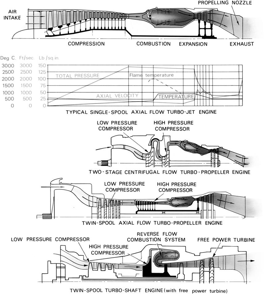
Another subdivision that can be made is whether the aeroengine drives a propeller (via the gas generator shaft or a free power turbine) and just basically pushes its exhaust gases out its exhaust section and thus pushes the plane forward (jet propulsion). This operational mode (turboshaft or turbojet) is independent of what type of compressor the gas turbine has, as we see in the family tree figure (see Figure 1–5). A turboshaft, which also has a large fan at the front (air intake) end, is called a turbofan engine.
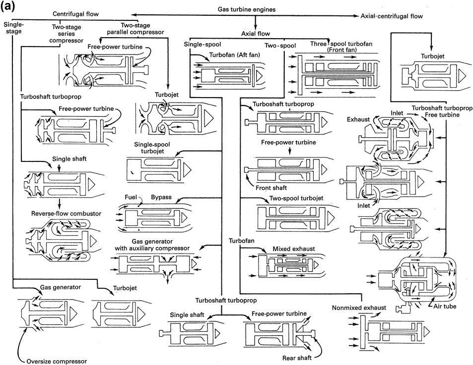
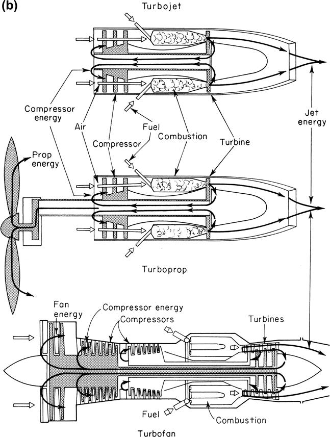
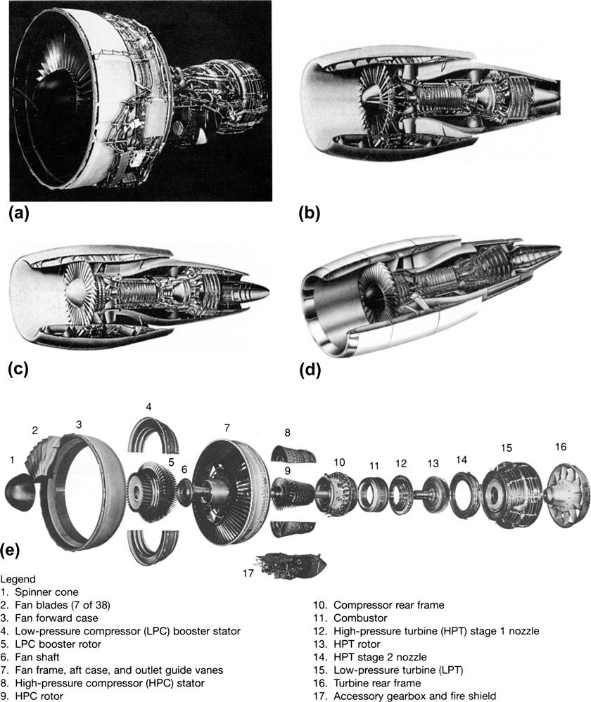
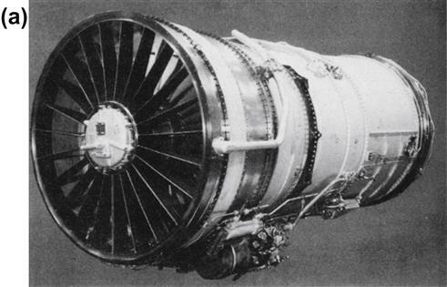
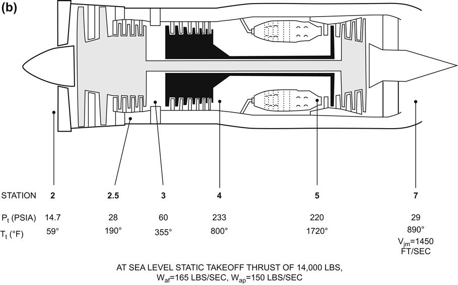
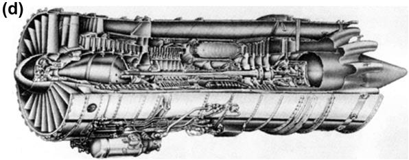
Examples of turbofan engines are the Trent engine family (Rolls Royce), the CF-6 engine family (General Electric), and the JT-8D engine family (Pratt and Whitney) (Figures 1–6 to 1–10).
Relationships Between Pressure, Volume, and Temperature1
Note that these Relationships are Essentially the Same Regardless of Whether the Gas Turbine is Used in Land, Sea, or Air Applications.
During the working cycle of the turbine engine, the airflow or “working fluid” receives and gives up heat, so producing changes in its pressure, volume, and temperature. These changes as they occur are closely related, for they follow a common principle that is embodied in a combination of the laws of Boyle and Charles. Briefly, this means that the product of the pressure and the volume of the air at the various stages in the working cycle is proportional to the absolute temperature of the air at those stages. This relationship applies for whatever means are used to change the state of the air. For example, whether energy is added by combustion or by compression, or is extracted by the turbine, the heat change is directly proportional to the work added or taken from the gas.
There are three main conditions in the engine working cycle during which these changes occur. During compression, when work is done to increase the pressure and decrease the volume of the air, there is a corresponding rise in the temperature. During combustion, when fuel is added to the air and burned to increase the temperature, there is a corresponding increase in volume while the pressure remains almost constant. During expansion, when work is taken from the gas stream by the turbine assembly, there is a decrease in temperature and pressure with a corresponding increase in volume.
Changes in the temperature and pressure of the air can be traced through an engine by using the airflow diagram in Figure 1–11. With the airflow being continuous, volume changes are shown up as changes in velocity.
The efficiency with which these changes are made will determine to what extent the desired relations between the pressure, volume, and temperature are attained. For the more efficient the compressor, the higher the pressure generated for a given work input; that is, for a given temperature rise of the air. Conversely, the more efficiently the turbine uses the expanding gas, the greater the output of work for a given pressure drop in the gas.
When the air is compressed or expanded at 100% efficiency, the process is said to be adiabatic. Since such a change means there is no energy loss in the process, either by friction, conduction, or turbulence, it is obviously impossible to achieve in practice; 90% is a good adiabatic efficiency for the compressor and turbine.
Changes in Velocity and Pressure
During the passage of the air through the engine, aerodynamic and energy requirements demand changes in its velocity and pressure. For instance, during compression, a rise in the pressure of the air is required and not an increase in its velocity. After the air has been heated and its internal energy increased by combustion, an increase in the velocity of the gases is necessary to force the turbine to rotate. At the propelling nozzle a high exit velocity is required, for it is the change in the momentum of the air that provides the thrust on the aircraft. Local decelerations of airflow are also required, for instance, in the combustion chambers, to provide a low velocity zone for the flame to burn.
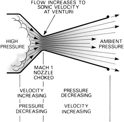
These various changes are effected by means of the size and shape of the ducts through which the air passes on its way through the engine. Where a conversion from velocity (kinetic) energy to pressure is required, the passages are divergent in shape. Conversely, where it is required to convert the energy stored in the combustion gases to velocity energy, a convergent passage or nozzle (Figure 1–12) is used. These shapes apply to the gas turbine engine where the airflow velocity is subsonic or sonic, i.e., at the local speed of sound. Where supersonic speeds are encountered, such as in the propelling nozzle of the rocket, athodyd, and some jet engines, a convergent-divergent nozzle or venturi (Figure 1–13) is used to obtain the maximum conversion of the energy in the combustion gases to kinetic energy.
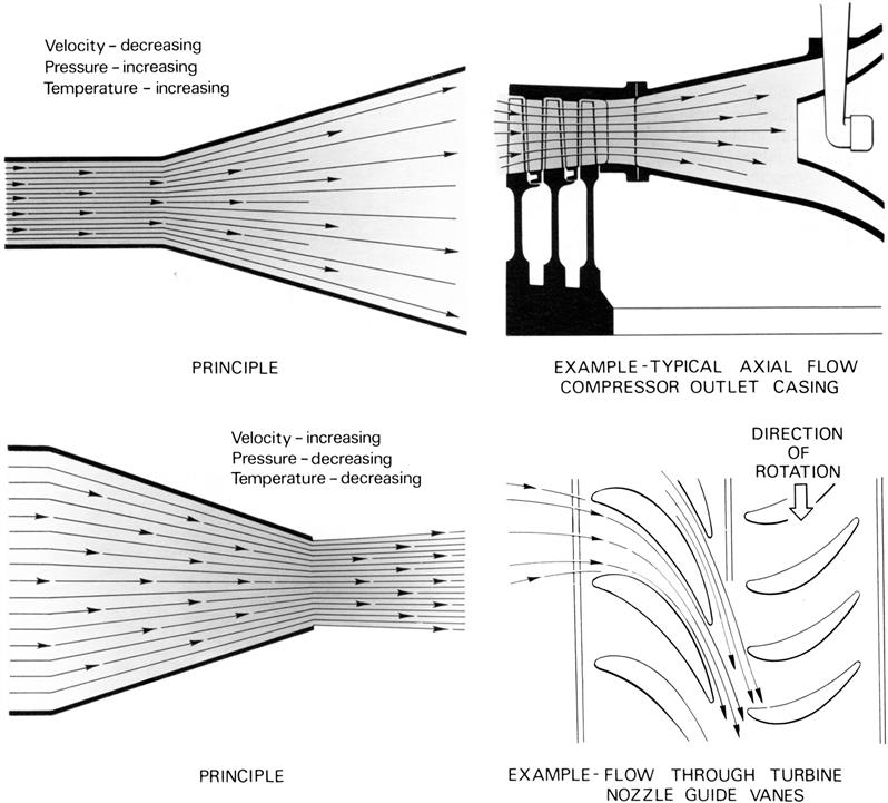
The design of the passages and nozzles is of great importance, for upon their good design will depend the efficiency with which the energy changes are effected. Any interference with the smooth airflow creates a loss in efficiency and could result in component failure due to vibration caused by eddies or turbulence of the airflow.
Airflow
The path of the air through a gas turbine engine varies according to the design of the engine. A straight-through flow system (Figure 1–11) is the basic design, as it provides for an engine with a relatively small frontal area and is also suitable for use of the bypass principle. In contrast, the reverse flow system gives an engine with greater frontal area, but with a reduced overall length. The operation, however, of all engines is similar. The variations due to the different designs are described in the subsequent paragraphs.
The major difference of a turbo-propeller engine is the conversion of gas energy into mechanical power to drive the propeller. Only a small amount of “jet thrust” is available from the exhaust system. The majority of the energy in the gas stream is absorbed by additional turbine stages, which drive the propeller through internal shafts.
As can be seen in Figure 1–11, the bypass principle involves a division of the airflow. Conventionally, all the air taken in is given an initial low compression and a percentage is then ducted to bypass, the remainder being delivered to the combustion system in the usual manner. This principle is conducive to improved propulsive efficiency and specific fuel consumption.
An important design feature of the bypass engine is the bypass ratio; that is, the ratio of cool air bypassed through the duct to the flow of air passed through the high-pressure system. With low bypass ratios, i.e., in the order of 1:1, the two streams are usually mixed before being exhausted from the engine. The fan engine may be regarded as an extension of the bypass principle, and the requirement for high bypass ratios of up to 5:1 is largely met by using the front fan in a twin or triple-spool configuration (on which the fan is, in fact, the low-pressure compressor) both with and without mixing of the airflows. Very high bypass ratios, in the order of 15:1, are achieved using propfans. These are a variation on the turbo-propeller theme but with advanced technology propellers capable of operating with high efficiency at high aircraft speeds.
On some front fan engines, the bypass airstream is ducted overboard either directly behind the fan through short ducts or at the rear of the engine through longer ducts; hence the term “ducted fan.” Another, though seldom used, variation is that of the aft fan.
Gas Turbines at Sea
In marine applications, the gas turbine is generally driving the ship’s or ferry’s propellers, via a gearbox, if it is providing the vessel’s propulsion. However, it may also be used to generate onboard power, as in the example below.
The gas turbine used is essentially the “same” machine as would be used for land service. The aeroderivative GT35 (now the SGT-500 under Siemens ownership) shown in a marine application in Figure 1–14 is also used in land-based service.
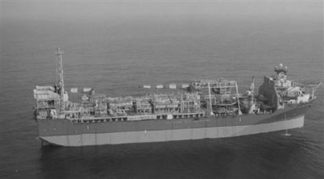
In Figure 1–14, this vessel is an FPSO (floating production, storage, and offloading) vessel, and power on board is provided by two SGT-500 gas turbines. One WHRG (waste heat recovery generator) for each gas turbine heats process water. The SGT-500 is a lightweight, high-efficiency, heavy-duty industrial gas turbine. Its special design features are high reliability and fuel flexibility. It is also designed for single lift, which makes the unit suitable for all offshore applications. The modular, compact design of the GT35C facilitates on-site modular exchange.
Gas Turbines: Details of Individual Applications
In the previous section we saw some basic examples of the gas turbine’s role in industry. In this section we will look at more detailed specifics of the individual applications in land, sea, and air usage.
Of all the industries today, power generation is by far the largest and also experiences the most growth.
Major Classes of Power Generation Application2
Table 1–1 summarizes the main classes of power generation application for which the gas turbine is a candidate, including examples of actual engines used. The descriptions that follow refer to items provided in Table 1–1.
TABLE 1–1
Main Classes of Power Generation Application
| Item | Plant Type | Examples of Applications | Examples of Engine | Power per Engine (MW) |
| 1 | Standby generator, simple cycle gas turbine | Office block Hospital |
Yanmar AT36C, 60C, 180C Turbomeca Astazou |
0.25–1.5 |
| 2 | Standby generator, diesel engine | Office block Hospital |
Caterpillar 352 V12 MTU 396 |
0.25–1.5 |
| 3 | Small-scale CHP, gas turbine | Hospital Small process factory |
EGT Hurricane NP PGT2 Allison 501 Solar mars EGT Tempest |
0.5–10 |
| 4 | Small-scale CHP, diesel, or natural gas-fired piston engine | Hospital Small process factory |
Petter A MB 190 |
0.5–10 |
| 5 | Large-scale CHP, gas turbine | Electricity and district heating for town of up to 25,000 people Large process factory, exporting electrical power |
ABB STAL GT10 GE LM2500 Coberra 6000 |
10–60 |
| 6 | Peak lopping units, simple cycle gas turbine | Supply to grid | ABB GT10 RR RB211 |
20–60 |
| 7 | Mid-merit power station, simple cycle gas turbine | Supply to grid | GE LM6000 RR Trent |
30–60 |
| 8 | Base load power station, gas turbine in combined cycle with steam plant | Supply to grid | WEC 50W GE PG9331(FA) |
50–450 |
| 9 | Base load power station, coal-fired steam plant | Supply to grid | 200–800 | |
| 10 | Base load power station, nuclear powered steam plant | Supply to grid | 800–2000 |

MTU = Motoren Turbinen Union; EGT = European Gas Turbines; NP = Nuovo Pignone;
MB = Mirrlees Blackstone; ABB = Asea Brown Broveri; GE = General Electric; RR = Rolls Royce;
WEC = Westinghouse Electric Company (now part of Siemens); CHP = Combined heat and power.
To convert MW to hp, multiply by 1341.
(Source: Rolls Royce.)
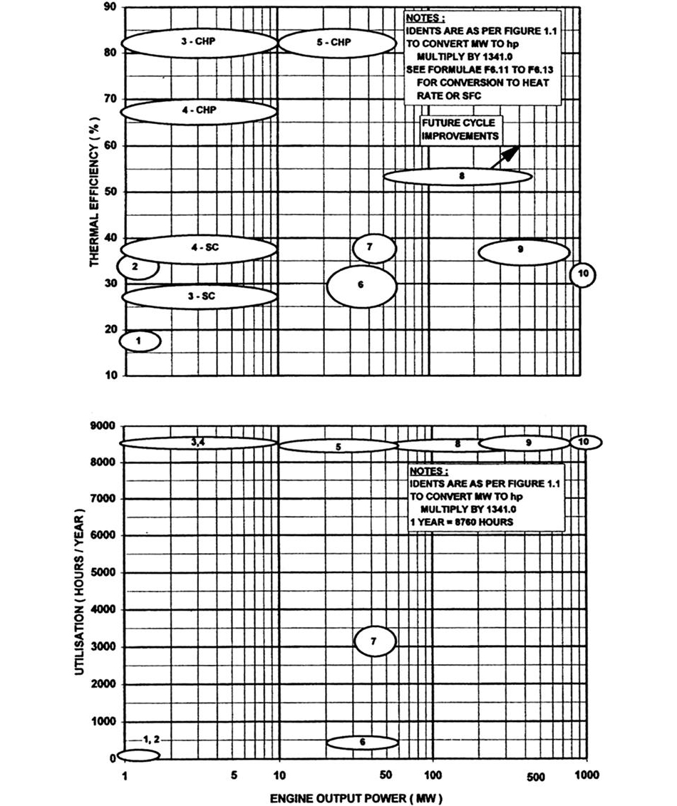
Figure 1–15 presents thermal efficiency and utilization for these applications in graphical form, again using the item numbers from Table 1–1. Utilization is the number of hours per year the application is typically fired.
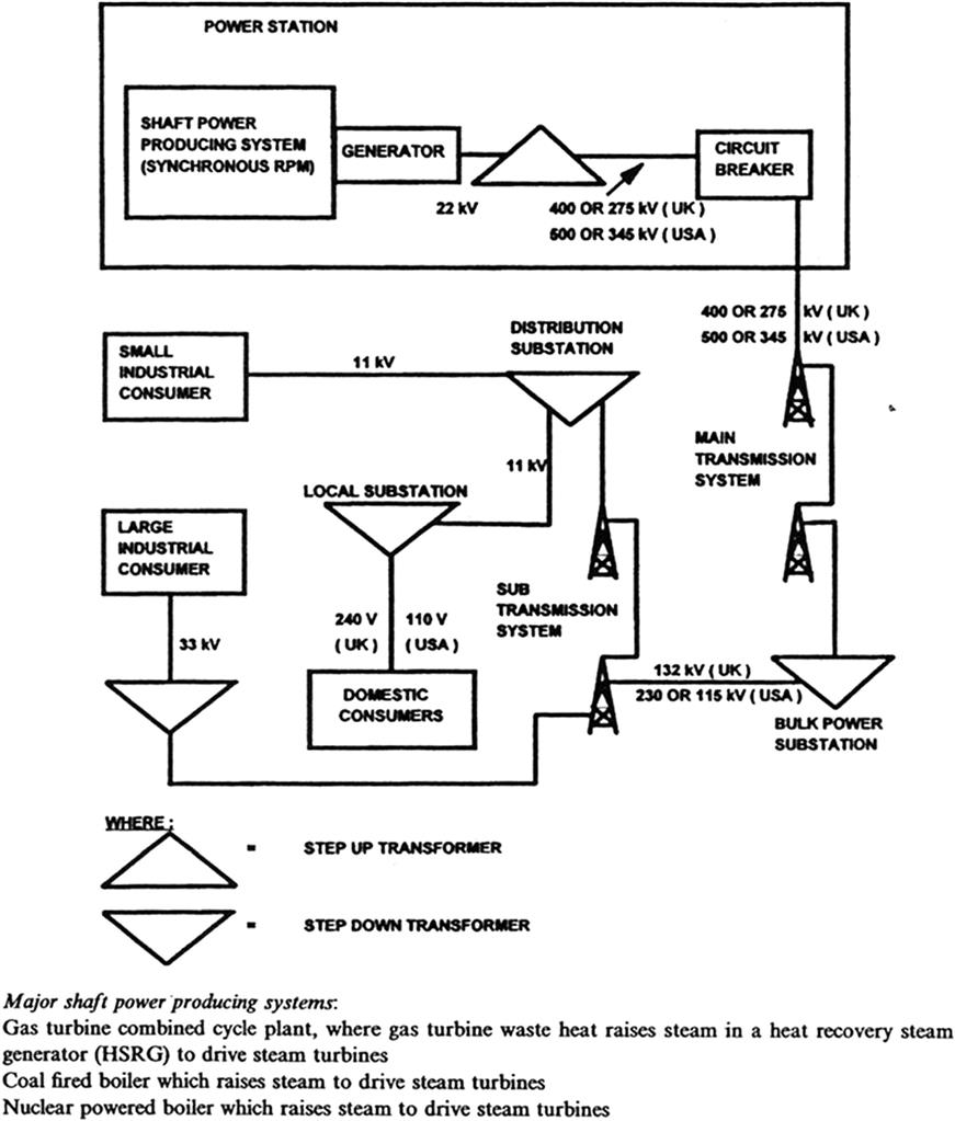
Grid System
Figure 1–16 illustrates a typical grid system for distribution of electrical power, showing voltages at key points. The shaft power system must operate at a constant synchronous speed to deliver electrical power at fixed frequency via an alternator. Frequencies are usually 50 Hz or 60 Hz depending upon the country.
Until recently the trend was for grids to be supplied by a few large power stations. More flexible distributed power systems are now becoming popular, however, due largely to the gas turbine’s viability even at smaller sizes. Here electricity is generated locally to the consumers whether by a CHP (combined heat and power) plant, or to a lesser extent the mid-merit power stations described later. Excess power is exported to the grid.
To illustrate the levels of power that must be transported, a city of one million people may have a peak demand of up to 2 GW. The average and peak consumption in a home for a family of four is around 1 kW and 6 kW, respectively, excluding space heating.
Standby Generators (Items 1 and 2, Table 1–1)
Standby generators are employed for emergency use, where there may be a loss of main supply that cannot be tolerated. Examples include hospitals and other public buildings in areas such as Japan, which may be prone to earthquakes. The power generated is used locally and the units are not connected to the grid system. Usually the fuel type is diesel. Key requirements are predominantly driven by the low utilization, and are outlined below in order of importance:
• Often low unit weight and volume are crucial (see below)
• Fast start and acceleration to rated power times may be very important
• Thermal efficiency and emissions levels are of secondary importance
The diesel engine is most popular, primarily due to the plethora of automotive and marine engines in the required power bracket, which reduces unit cost via high production volume. The gas turbine has made some inroads, particularly where weight and volume must be limited, for instance, if the standby generator is located on the roof of an office block with limited load-bearing capability.
Gas turbine engines in this sector are usually simple cycle, single spool rather than free power turbine engines. This is because the reduced number of components reduces unit cost and because part speed torque is unimportant. Following the start sequence the engine remains at synchronous speed to ensure constant electrical frequency. Centrifugal compressor systems with pressure ratios of 5:1–10:1 are employed to minimize unit cost, and because the efficiency of axial flow compressors at such low flow rates is poor. The turbine blades, and usually the nozzle guide vanes, are uncooled, leading to SOT (stator outlet temperature) levels of typically 1100–1250 K.
Major Shaft Power Producing Systems
• A gas turbine combined cycle plant, where gas turbine waste heat raises steam in a heat recovery steam generator (HRSG) to drive steam turbines.
• A coal-fired boiler also generates steam to drive steam turbines.
• A nuclear powered boiler that raises steam to drive steam turbines.
Small-Scale Combined Heat and Power—CHP (Items 3 and 4, Table 1–1)
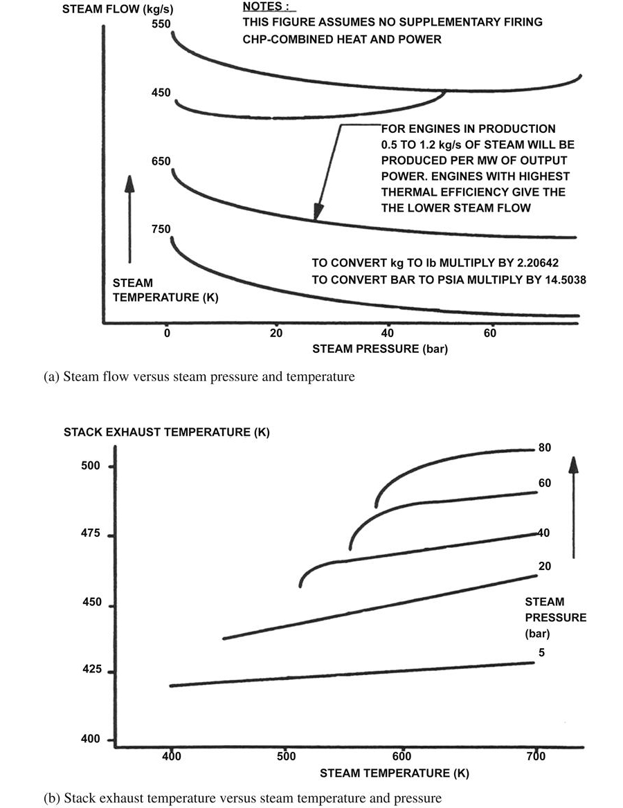
In this application the waste heat is typically utilized in an industrial process. The heat may be used directly in drying processes or more usually it is converted by an HRSG (heat recovery steam generator) into steam for other uses. Table 1–1 shows the presentation manufacturers usually employ to publish the steam raising capability of an engine. Most CHP systems burn natural gas fuel. The electricity generated is often used locally, and any excess exported to the grid. The key power plant selection criteria in order of importance are:
1. Thermal efficiency, for both CHP and simple cycle operation. The latter becomes more significant if for parts of the year there is no use for the full exhaust heat.
2. Heat to power ratio is important as electricity is a more valuable commodity than heat. Hence a low ratio is an advantage as the unit may be sized for the heat requirement and any excess electricity sold to the grid.
3. The grade (temperature) of the heat is very important in that the process usually demands a high temperature.
4. Owing to the high utilization, low unit cost, start, and acceleration times are all of secondary importance, as are weight, volume, and part speed torque.
The attributes of the gas turbine engine best meet the above criteria, and hence it is the market leader. The diesel engine still retains a strong presence, however, particularly for applications where substantial low-grade heat is acceptable, or where the importance of simple cycle thermal efficiency is paramount.
Gas turbines for this application are usually custom designed and tend to be single spool. Below 3 MW centrifugal compressors are used exclusively, with pressure ratios of between 8:1 and 15:1. This is a compromise between unit cost and simple cycle and CHP thermal efficiencies. At the lower end of the power bracket SOT tends to be 1300–1400 K, which requires only the first stage turbine nozzle guide vanes to be cooled. At the higher end of the power bracket the first stage rotor blades may also be cooled, allowing SOT levels of up to 1450 K. This becomes viable because of the increased size of the blades, and because the increased unit cost may be supported at the higher power.
Large-Scale CHP (Item 5, Table 1–1)
Here the waste heat is almost exclusively used to raise steam, which is then used in a large process application such as a paper mill, or for district heating. Again, the electricity generated may be used locally or exported to the grid. The importance of performance criteria to engine selection are as for small-scale CHP, except that emissions legislation is more severe at the larger engine size (Figure 1–17).
Here gas turbines are used almost exclusively. High-grade heat is essential and the weight and volume of diesel engines prohibitive at these power outputs. Furthermore, the gas turbines used are often applicable to other markets, such as oil and gas and marine, which reduces unit cost. Aeroderivative gas turbines are the most common, though some heavyweight engines are used. Aeroderivatives usually employ the core from a large civil turbofan as a gas generator, with a custom designed free power turbine for industrial use. Heavyweight engines are designed specifically for industrial applications and as implied are far heavier than aeroderivatives, their low cost construction employing solid rotors, thick casings, etc.
The gas turbine configuration is usually a free power turbine. While this is not necessary for CHP applications, it is essential to also allow use in oil and gas and marine. Axial flow compressors are used exclusively with overall pressure ratios between 15:1 and 25:1. The aeroderivatives are at the top end of this range as this pressure ratio level results from a civil turbofan core. This pressure ratio is a compromise between that required for optimum CHP thermal efficiency of 20:1 and the 35:1 for optimum simple cycle efficiency. These values apply to the typical SOT of between 1450 K and 1550 K. Advanced cooling systems are employed for at least both the HP turbine first stage nozzle guide vanes and blades.
Applications that Supply Solely to a Grid System (Items 6 to 10, Table 1–1)
Power plants supplying a grid fall into three categories:
1. Peak lopping engines have a low utilization, typically less than 10%. They are employed to satisfy the peak demand for electrical power that may occur on mid-weekday evenings as people return home and switch on a multitude of appliances.
2. Base load power plants achieve as near to 100% utilization as possible to supply the continuous need for electrical power.
3. Mid-merit power plants typically have 30–50% utilization. They serve the extra demand for electricity that is seasonal, such as the winter period in temperate climates where demand increases for domestic heating and lighting.
The considerations in selecting the type of power plant for a base load power station are as follows:
1. Thermal efficiency and availability are paramount.
2. Unit cost is of as high importance as the capital investment and period of time before the power station comes on line to generate a return on the investment are large.
3. Cost of electricity is a key factor in selecting the type of power plant and fuel price is a major contributor to this. Coal, nuclear, and oil-fired plants all compete with the gas turbine.
In all cases weight and volume are of secondary importance. Other specific comments are as follows:
• For base load plants, start and acceleration times are unimportant.
• For peak lopping power stations unit cost is crucial, time onto full load is very important, and thermal efficiency relatively unimportant.
• Mid-merit power stations are a compromise with some unit cost increase over and above peak loppers being acceptable in return for a moderate gain in thermal efficiency.
Peak loppers are mostly simple cycle gas turbines burning either diesel or natural gas, and some diesel engines are used at the lower power end. This is because the unit cost and time onto load are far lower than for other available alternatives, which involve steam plant. Both aeroderivative and heavyweight gas turbines are employed as peak loppers, either single spool or free power turbine, and with pressure ratios between 15:1 and 25:1. SOT may be as high as 1500 K, particularly where the unit is also sold for CHP and mechanical drive applications that demand high thermal efficiency.
For base load applications the gas turbine is used in combined cycle, to achieve the maximum possible thermal efficiency. It competes here with coal- and the nuclear-fired steam plants.
Historically, coal-fired plants have always had the biggest market share. In recent years the combined cycle as turbine has taken an increasing number of new power station orders due to the availability of natural gas leading to a competitive fuel price, higher thermal efficiency, and lower emissions, and the fact that the power stations may often be built with a lower capital investment. This has been supported by advances in gas turbine technology, which have increased both thermal efficiency and the feasible power output from a single engine. In particular, improvements in mechanical design have allowed SOT, and the last stage turbine stress level, to increase significantly. This particular stress is a limiting feature for large single spool engines in that as mass flow is increased at synchronous speed, so too must the turbine exit area to keep to an acceptable Mach number.
In some countries a relatively modern coal-fired plant has even “slid down the merit table” and is now only being used in mid-merit applications. However, in parts of the world where there is no natural gas and an abundance of coal, coal-fired steam plants will continue to be built for the foreseeable future. For nuclear power the case is complex, depending upon individual government policies and subsidies.
For base load applications above 50 MW the gas turbines are almost exclusively custom designed, single spool heavyweight configurations. The chosen pressure ratio is the optimum or combined cycle thermal efficiency at the given SOT, though this curve is relatively flat over a wide range of pressure ratios. Usually the higher pressure ratio on this flat portion is chosen to minimize steam plant entry temperature for mechanical design considerations. Engines currently in production are in the 1450–1550 K SOT range, and pressure ratios range from 13:1–16:1. For a number of concept engines SOT levels of 1700–1750 K are under consideration, with pressure ratios of 19:1–25:1. These employ advanced cycle features such as steam cooling of NGVs and blades. These engines are targeted at a combined cycle thermal efficiency of 60%. Aeroderivative gas turbines are currently limited to around 50 MW due to the size of the largest aeroengines. In this power bracket they are competitive in combined cycle, particularly at higher SOT levels.
Mid-merit power stations employ simple cycle gas turbines of a higher technology level than those used for peak lopping. The higher unit cost is justified by the higher thermal efficiency, given the higher utilization. Most engines are aeroderivative but at pressure ratios of the order of 25:1–35:1 for optimum simple cycle thermal efficiency. Corresponding SOT levels are 1500–1600 K.
Closed Cycles
Here the working fluid, often helium, is recirculated from turbine exit to compressor entry via pre-cooling heat exchangers. Advantages of a closed, as opposed to open, cycle include the following:
• No inlet filtration requirements or blade erosion problems.
• Reduced turbomachinery size, due to the working fluid being maintained at a high pressure and density. In addition, helium offers a high specific heat.
• The use of energy sources unsuited to combustion within an open gas turbine cycle, such as nuclear reactors or alternative fuels such as wood and coal. Helium offers a short half-life for use in radioactive environments.
• A flat SFC characteristic at part power as compressor entry pressure may be modulated, preserving cycle pressure ratio and SOT.
However, few closed cycle plants have been manufactured despite numerous studies for power generation and submarine propulsion. This is because the above advantages have been offset by high unit cost and modest thermal efficiency due to the SOT limit of around 1100 K dictated by nuclear reactor or heat exchanger mechanical integrity limits. The high unit cost results from the plant complexity and the implications of designing for very high pressures.
Industrial Mechanical Drive Applications
Here the engine is used to drive a pump or compressor. The most prolific example is the gas and oil industry that typically orders 1 GW per year of new engines. The majority of engines are installed onshore, although there is an offshore sector where engines are located on platforms.
This industry also has the need for some local primary power generation and emergency power generation. The requirements here are as per conventional power generation but the importance of low weight and volume is amplified.
The Gas and Oil Pipeline System
Figure 1–18 shows the configuration of a natural gas pipeline system, in which gas is pumped from a well head to industrial and domestic consumers. Pipelines have diameters of typically 915 mm (36 in) to 1420 mm (56 in), and are usually underground. A notable exception is in permafrost areas where they must be raised to avoid melting the permafrost. These systems may extend over thousands of kilometers, with compression stations approximately every 200 km. For example, the trans-Canada pipeline runs from the Alberta province in Canada to the east coast of the United States. The power plant burns natural gas tapped off the pipeline, and drives a centrifugal compressor. Figure 1–18 also shows the typical flow rate of natural gas versus pumping power, and the pipeline compressor pressure ratio. For comparison, a family of four may consume up to 10 standard cubic meters per day in the winter period. A further use for gas turbines is to pump water into depleted natural gas fields to increase gas extraction.
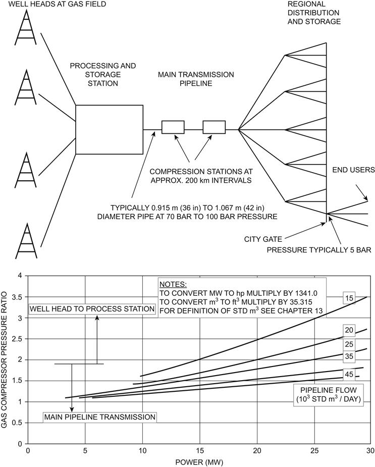
Oil pipelines are less complex. Oil is pumped from a well head to a refinery, and occasionally distillate fuels are then pumped to large industrial users. Extracting oil from the well may involve pumping gas down to raise pressure and to force oil up the extraction pipe by bubbling gas through it.
Engine Requirements
The major power blocks required are around 6–10 MW, 15 MW, and 25–30 MW. These power levels are generally beyond the practical size for a high-speed diesel engine given the requirements outlined below, and hence gas turbines are used almost exclusively. In order of importance these requirements are:
1. Low weight, as the engines often have to be transported to remote locations, where it also may be difficult and costly to build substantial foundations.
2. Good base load thermal efficiency, since utilization is as near 100% as possible.
3. Reasonable part power torque, to respond to load changes on the gas compressor. However, a fast start time is not essential, and a loading rate of 2 minutes from idle to full power is typical.
For offshore well heads the engine must be located on a platform; hence the importance of low weight is amplified and low volume essential. While the gas or oil may have a high pressure as it comes out of the ground it invariably needs further pressurization to pipe it back onshore. The engine may drive the compression unit mechanically as described above, or sometimes via an electric motor. In the latter instance a CHP arrangement supplies power for other needs, such as electricity for the drill and heat for uses such as natural gas processing or space heating.
For the middle and higher power bracket, simple cycle, free power turbine aeroderivatives best meet the above criteria, and are used almost exclusively. Pressure ratios of 20:1–25:1 and SOT levels of 1450–1550 K are typical, leading to thermal efficiency levels in the mid to high thirties. Engines include the Cooper Rolls Coberra 6000 and the GE LM2500, which are also utilized in power generation applications. For the lower power bracket, both custom designed industrial engines such as the Solar Mars, and aeroderivatives such as the Allison 501, are used with lower pressure ratio and SOT levels leading to thermal efficiencies in the low thirties.
Automotive Applications
The Gas Turbine Versus Reciprocating Engines
The first gas turbine propelled automotive vehicle was the Rover JETI produced in the U.K. in 1950, the design team being led by Maurice Wilks and Frank Bell. The engine had a free power turbine and produced 150 kW from a simple cycle; the vehicle fuel consumption was 5.4 km/liter (15.2 mpg). Over the ensuing decades significant effort has been spent on automotive programs; however, the diesel and gasoline engines have continued to dominate, with the gas turbine only achieving a presence in specialist applications. The contributory issues are explored in this section, but there are three key reasons:
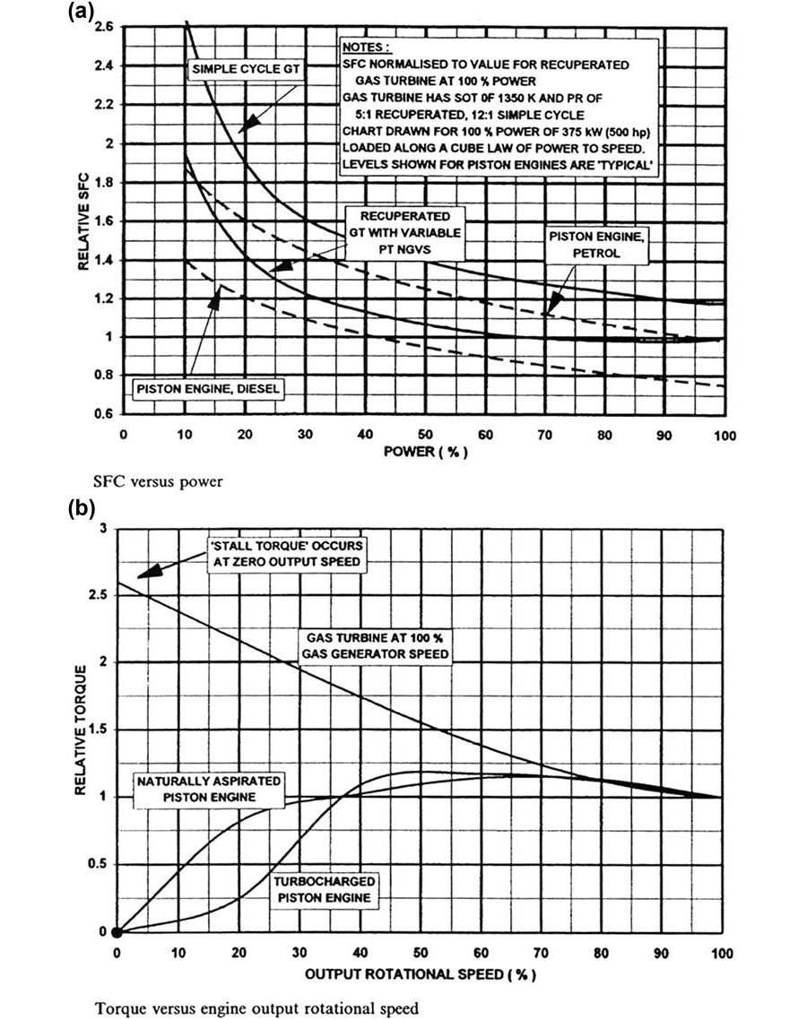
1. The poor part load thermal efficiency of the gas turbine, despite the use of a recuperated cycle with variable area nozzle guide vanes. To improve thermal efficiency, ceramic turbine technology has been researched for decades, but progress towards a production standard has been frustratingly slow.
2. There is a relatively long acceleration time of the gas turbine gas generator spool from idle to full load.
3. Huge capital investment would be required in gas turbine manufacturing facilities.
These disadvantages have mostly outweighed the benefits of the gas turbine, which are:
• Better part speed torque capability as described in Figure 1–20, which reduces the need for varying gear ratios.
One other use for gas turbine engines has been in thrust-propelled vehicles for attempts on the world land speed record. In 1983 Richard Nobel’s “Thrust 2” achieved 1019 km/h (633 mph) using a Rolls Royce Avon turbojet. In 1997 his “Thrust SSC” piloted by Andrew Green exceeded the speed of sound, and set a new world land speed record of 1220 km/h (763 mph), using two Rolls Royce Spey turbofans.
The Gasoline Engine Versus the Diesel Engine
Figure 1–19 includes curves of thermal efficiency and torque versus part load power for the gasoline engine. Overall it has worse SFC than the diesel engine because to avoid pre-ignition its compression ratio is lower, typically 10:1, contrasting with 15:1–20:1 for diesels. Whereas the Otto cycle in a gasoline engine has combustion at constant volume, producing increased pressure, in a diesel engine it is at constant pressure. Both engines can be turbocharged to increase power by raising inlet density and hence air mass flow. The weight and size saving can be significant, though with some expense in terms of response time, due to turbo lag as the turbocharger spool accelerates.
The main advantage of the gasoline engine is that it has lower weight and volume, which approach those for the gas turbine at the 50 kW required for a typical family sedan. Hence gasoline engines are used where fast vehicle acceleration is essential, space is at a premium, and worsening of SFC is acceptable. Diesel engines dominate for applications such as trucks where fuel consumption is paramount due to high utilization, engine weight and volume relative to the vehicle are low, and high vehicle acceleration is not a priority.
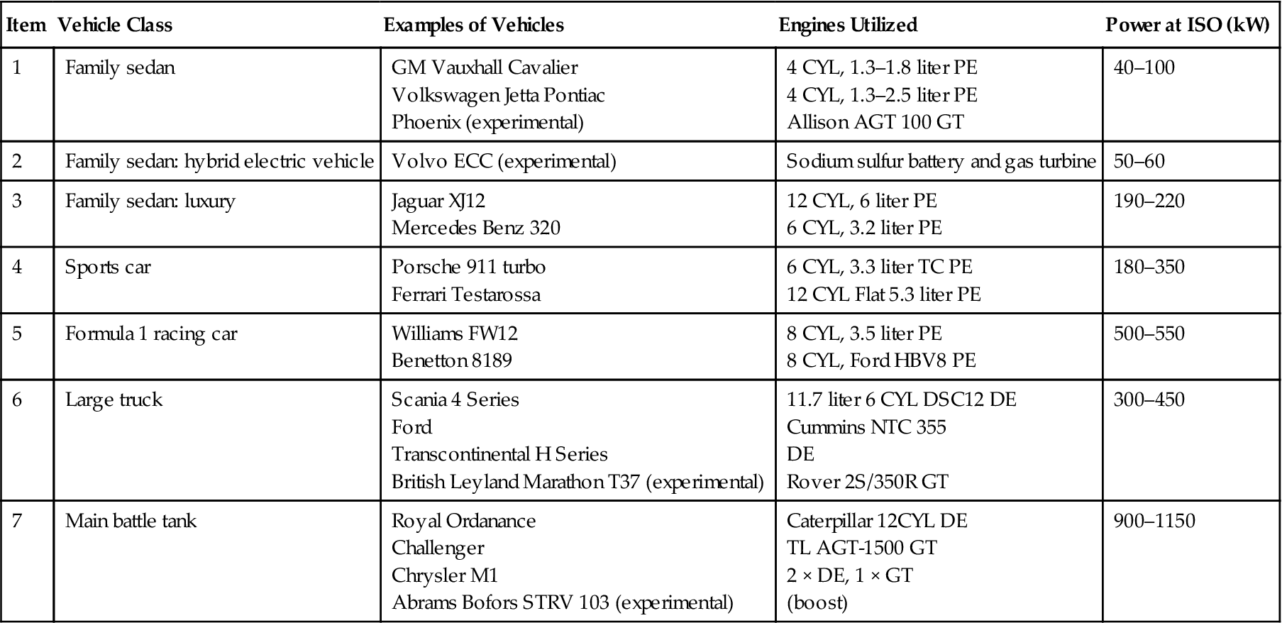
Table 1–2 lists the major categories of the automotive vehicle and the engines used in them.
TABLE 1–2
Major Categories of Automotive Vehicle. Examples and Engine Types
| Item | Vehicle Class | Examples of Vehicles | Engines Utilized | Power at ISO (kW) |
| 1 | Family sedan | GM Vauxhall Cavalier Volkswagen Jetta Pontiac Phoenix (experimental) |
4 CYL, 1.3–1.8 liter PE 4 CYL, 1.3–2.5 liter PE Allison AGT 100 GT |
40–100 |
| 2 | Family sedan: hybrid electric vehicle | Volvo ECC (experimental) | Sodium sulfur battery and gas turbine | 50–60 |
| 3 | Family sedan: luxury | Jaguar XJ12 Mercedes Benz 320 |
12 CYL, 6 liter PE 6 CYL, 3.2 liter PE |
190–220 |
| 4 | Sports car | Porsche 911 turbo Ferrari Testarossa |
6 CYL, 3.3 liter TC PE 12 CYL Flat 5.3 liter PE |
180–350 |
| 5 | Formula 1 racing car | Williams FW12 Benetton 8189 |
8 CYL, 3.5 liter PE 8 CYL, Ford HBV8 PE |
500–550 |
| 6 | Large truck | Scania 4 Series Ford Transcontinental H Series British Leyland Marathon T37 (experimental) |
11.7 liter 6 CYL DSC12 DE Cummins NTC 355 DE Rover 2S/350R GT |
300–450 |
| 7 | Main battle tank | Royal Ordanance Challenger Chrysler M1 Abrams Bofors STRV 103 (experimental) |
Caterpillar 12CYL DE TL AGT-1500 GT 2 × DE, 1 × GT (boost) |
900–1150 |
PE = Petrol engine; TC = Turbocharged; RR = Rolls Royce; GM = General Motors; DE = Diesel engine; GT= Gas turbine; TL = Textron Lycoming;
ISO = Standard ambient, at sea level; CYL = Cylinder.
To convert kW to hp, multiply by 1.341.
(Source: Rolls Royce.)
The Hybrid Electric Vehicle
Stringent emissions legislation is creating a niche market in certain parts of the world, such as California. Pure electric vehicles have limited performance and range before battery recharging is required, even those using the most advanced battery systems such as sodium sulfur. To overcome this, a heat engine may also be fitted in one of two possible hybrid configurations, currently the subject of many development studies.
Figure 1–20 describes the various modes in which the two hybrid electric vehicle configurations may operate. For a range extender there are two modes of operation. Mode A is that of a conventional electric vehicle, where the battery provides traction power to the wheel motors via power electronics. In mode B the heat engine drives a generator that provides power to charge the battery. In this application when operative the gas turbine runs at maximum power, where response is unimportant and the SFC difference versus piston engines is lowest.
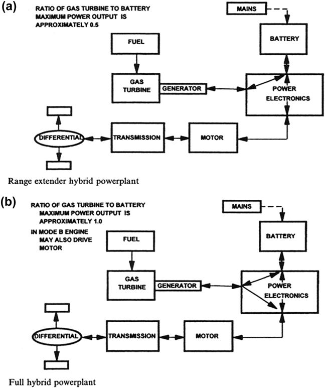
For a full hybrid power plant, in mode B the engine may also drive the motor.
Marine Applications
Marine propulsion uses diesel engines, gas turbines, or oil- or nuclear-fired steam plants. Diesel engines are split into two main types. The smaller high speed (1500 rpm) variety burn a highly refined light diesel fuel as per marine gas turbines. Larger low speed or cathedral diesels burn far heavier diesel oil, the low speed (120 rpm) and indirect injection not requiring rapid fuel vaporization for combustion. While most marine propulsion uses diesel engines the gas turbine is popular in certain applications.
The first instance of naval propulsion using gas turbines was in 1947 in the U.K. using a Metrovick “Gatric” engine in a modified gun boat. This was based on the F2 jet engine but with a free power turbine in the tail pipe and burning diesel. Sea trials lasted four years and convinced skeptics that operation of a simple cycle lightweight engine at sea was practical. Metopolitan Vickers was later taken over by Rolls Royce.
Another early development was the Rolls Royce RM60 double intercooled and recuperated engine, of 4.0 MW. This had a flat SFC curve and was intended as a single engine for small ships, and as a cruise engine for larger ones. It was fitted to HMS Grey Goose in 1953, which became the world’s first solely gas turbine propelled ship and spent four years at sea. Though mostly technically successful, the engine did not see production, being too complex for the patrol boat role and inferior to diesels as a cruise engine.
The first operational case was the use of three Bristol Engine Company (again later taken over by Rolls Royce) Proteus engines in a fast patrol boat in 1958.
Marine propulsion system requirements differ significantly from land-based units. Owing to the large vessel inertia engine, acceleration time is generally not critical. Also the impact of current emissions legislation is negligible, particularly out at sea where pollution concentrations are low. The International Maritime Organization (IMO) is reluctant to introduce stringent legislation that a gas turbine could meet but diesel engines could not.
Major Classes of Marine Vessel
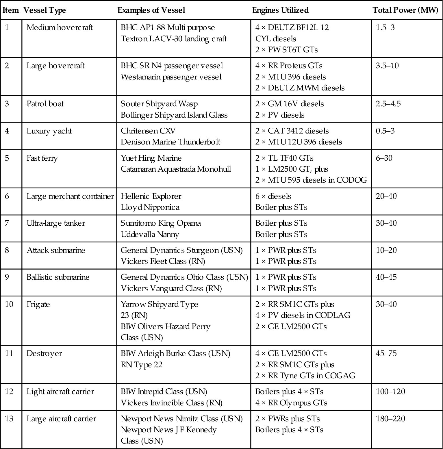
The major classes of marine vessel for which gas turbine engines are candidates are summarized in Table 1–3. Examples of actual vessels and the engines used are provided. The gas turbine competes with the diesel engine and nuclear power plant utilizing boilers and steam turbines. At the time of writing the oil-fired steam plant is becoming rare in new vessels, but remains in service.
TABLE 1–3
Major Classes of Marine Vessels
| Item | Vessel Type | Examples of Vessel | Engines Utilized | Total Power (MW) |
| 1 | Medium hovercraft | BHC AP1-88 Multi purpose Textron LACV-30 landing craft |
4 × DEUTZ BF12L 12 CYL diesels 2 × PW ST6T GTs |
1.5–3 |
| 2 | Large hovercraft | BHC SR N4 passenger vessel Westamarin passenger vessel |
4 × RR Proteus GTs 2 × MTU 396 diesels 2 × DEUTZ MWM diesels |
3.5–10 |
| 3 | Patrol boat | Souter Shipyard Wasp Bollinger Shipyard Island Glass |
2 × GM 16V diesels 2 × PV diesels |
2.5–4.5 |
| 4 | Luxury yacht | Chritensen CXV Denison Marine Thunderbolt |
2 × CAT 3412 diesels 2 × MTU 12U 396 diesels |
0.5–3 |
| 5 | Fast ferry | Yuet Hing Marine Catamaran Aquastrada Monohull |
2 × TL TF40 GTs 1 × LM2500 GT, plus 2 × MTU 595 diesels in CODOG |
6–30 |
| 6 | Large merchant container | Hellenic Explorer Lloyd Nipponica |
6 × diesels Boiler plus STs |
20–40 |
| 7 | Ultra-large tanker | Sumitomo King Opama Uddevalla Nanny |
Boiler plus STs Boiler plus STs |
30–40 |
| 8 | Attack submarine | General Dynamics Sturgeon (USN) Vickers Fleet Class (RN) |
1 × PWR plus STs 1 × PWR plus STs |
10–20 |
| 9 | Ballistic submarine | General Dynamics Ohio Class (USN) Vickers Vanguard Class (RN) |
1 × PWR plus STs 1 × PWR plus STs |
40–45 |
| 10 | Frigate | Yarrow Shipyard Type 23 (RN) BIW Olivers Hazard Perry Class (USN) |
2 × RR SM1C GTs plus 4 × PV diesels in CODLAG 2 × GE LM2500 GTs |
30–40 |
| 11 | Destroyer | BIW Arleigh Burke Class (USN) RN Type 22 |
4 × GE LM2500 GTs 2 × RR SM1C GTs plus 2 × RR Tyne GTs in COGAG |
45–75 |
| 12 | Light aircraft carrier | BIW Intrepid Class (USN) Vickers Invincible Class (RN) |
Boilers plus 4 × STs 4 × RR Olympus GTs |
100–120 |
| 13 | Large aircraft carrier | Newport News Nimitz Class (USN) Newport News J F Kennedy Class (USN) |
2 × PWRs plus STs Boilers plus 4 × STs |
180–220 |
131-1C = British Hovercraft Co; RR = Rolls Royce; TL = Textron Lycoming; PW = Pratt & Whitney;
GM = General Motors; PV = Paxman Valenta; CAT = Caterpillar; PWR = Pressurized water reactors;
GTs = Gas turbines; STs = Steam Turbines; BIW = Bath Iron Works; RN = UK Royal Navy; USN = US Navy.
(Source: Rolls Royce.)
Marine Vessel Propulsion Requirements
Figure 1–21 illustrates and quantifies the elements that comprise the total power requirement for vessel forward motion. A vessel moving through calm water creates two waveforms, one with a high water pressure at the bow, the other a reduced pressure at the stern. The energy to create this wave system is derived from the vessel via the wave making resistance. At high speed the wave resistance is dominant. Indeed for a given hull design a critical hull speed for wave making resistance is reached, where the vessel literally climbs a hill of water, with the propulsion thrust tilting upward, and it is uneconomical to go beyond this speed. The sinusoidal effect visible superimposed on the curve of wave making resistance is due to interactions of the bow and stern wave systems. The skin friction resistance, or friction form resistance, is also a major contributor to the total resistance. This is the friction between the hull and the water.
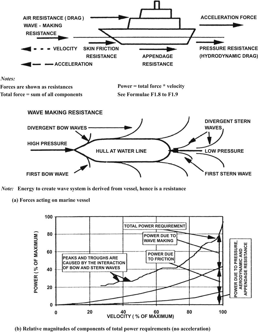
The pressure resistance, hydrodynamic drag, or form drag is due to flow separations of the water around the hull creating an adverse pressure field. Any resulting eddies or vortices are in addition to the waves created by the wave making resistance.
The air resistance due to the drag of the vessel above the water line contributes less than 5% of the total resistance. Often for low speed vessels little effort is spent in aerodynamic profiling.
The above four resistances comprise the naked resistance. The appendage resistance must then be added to evaluate the total resistance. This is the loss incurred by rudders, bilge keels, propellers, etc., and is less than 10% of the total resistance.
Traditionally these resistances for a vessel design are evaluated by model testing in a water tank and then using non-dimensional groups to scale up the resulting formulae and coefficients to the actual vessel size. This process is complex. The power requirement approximates to a cube law versus vessel velocity for displacement hulls, which support weight by simple buoyancy. Resistance is also dependent on vessel displacement (i.e., weight). Power approaches a square law for semi-planing hulls, which produce lift hydrodynamically.
Engine Load Characteristics
Ship engines drive either a conventional propeller or a waterjet via a gearbox. The latter consists of an enclosed pump that sends a jet of water rearwards. Since both devices pump incompressible water, power versus shaft speed adheres closely to a fluid dynamics cube law. For a propeller the vessel speed determines the shaft speed; in the absence of propeller blade slippage these are uniquely related. As the number of engines driving changes, engine operation moves between different possible cube laws, with slippage likely for fewer propellers driving. In the engine concept design phase cube laws are a reasonable assumption, but at the earliest opportunity the law(s) for the actual propeller or waterjet should be obtained from the manufacturer. Variable pitch propellers are often employed, which mainly affect the lowest speed characteristics.
Also shown are the resulting characteristics of engine speed versus ship speed. The cube laws for power versus ship speed, and power versus engine output speed combine to make engine output speed directly proportional to ship speed. With one engine driving, however, engine output speed is almost 20% higher than with two to achieve a given ship speed, hence propeller speed, due to slippage of the loaded propeller. These multiple load characteristics must be considered when designing a gas turbine for a multi-engine vessel.
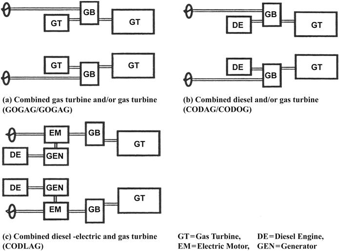
CODAG, CODOG, COGAG, and CODLAG Propulsion Systems
Figure 1–22 presents schematic diagrams of the above systems.
• In CODAG (COmbined Diesel And Gas turbine) systems a diesel engine provides propulsive power at low ship speed, but at high speeds the gas turbine is fired providing the relatively large additional power requirement dictated by the cube law.
• In CODOG (COmbined Diesel Or Gas turbine) systems the gearing is arranged such that only the diesel or gas turbine may drive the propeller or water jet at a given time.
• COGAG (COmbined Gas turbine And Gas turbine) and COGOG systems use a small gas turbine at low ship speed and/or a larger engine for high ship speeds.
• CODLAG (COmbined Diesel eLectric And Gas turbine) systems use an electric motor and diesel powered generator for low speeds. An important feature is low noise for anti-submarine work.
• IED (Integrated Electric Drive) or FEP (Full Electric Propulsion) is the subject of serious study for large naval vessels. Here the gas turbine drives a generator to provide electrical power for propulsion, ship services or, crucially, future weapons systems. A constant output speed of 3600 rpm is likely, though a gearbox or even new high power frequency converters may be employed. Such electric propulsion has long been employed on merchant vessels, but not to date on gas turbine warships.
Hovercraft (Items 1 and 2, Table 1–3)
Hovercraft use a fan to maintain pressure under side skirts to hover above the water surface and air propellers to provide thrust for propulsion. The ratio of power required for propulsion to that for hovering is between 5:1 and 10:1. These vessels are designed for high speed. They are generally used in applications such as commercial passenger ferries or landing craft where the vessel spends most of its time at maximum speed. The key power plant criteria in order of importance are:
The output power is below 10 MW, hence a high-speed diesel engine is practical. The diesel engine has the best high power SFC but the gas turbine the lowest weight. Consequently both power plant types are used. The gas turbine configuration is simple cycle for minimum weight, with a free power turbine. Typically SOT levels of 1250 K are employed with pressure ratios of around 7:1, the low values partly reflecting the predominance of older engine designs in current applications.
Monohull Patrol Boat and Luxury Yacht (Items 3 and 4, Table 1–3)
These vessels spend most of their time cruising at low speed. Because of the cube law relationship of output power to vessel speed most of the operational time is at a very low percentage output power, even allowing for twin engine vessels only cruising on one engine. The key requirement is good part load SFC; given this and the small size the diesel engine dominates.
Fast Ferry (Item 5, Table 1–3)
Fast ferries for commercial passenger transport represent a growing market. These often employ catamaran multiple hull configurations and hydrofoil operation where a lifting surface raises much of the hull above the water at high speeds. While the vessel speed is still below that of the hovercraft it has the advantage of being able to operate in rough seas. Like the hovercraft, most of its time is at high power, and key requirements are as for the hovercraft. Low weight is particularly important given the higher speed than for other classes. Power required increases with weight even for a hydrofoil, and the fuel weight for the range must be considered when operating at high speed.
For large fast ferries the power requirement is beyond that of a diesel engine and the gas turbine dominates. There is often a CODOG arrangement with diesel engines for harbor maneuvering. At the smaller end the gas turbine and diesel share the market.
Simple cycle gas turbines are employed, usually low weight aeroderivatives, with pressure ratios of 15:1–25:1. SOT is between 1450 and 1550 K with advanced cooled nozzle guide vanes and rotor blades.
Large Merchant Container and Ultra-Large Tanker (Items 6 and 7, Table 1–3)
Large merchant container ships are also propelled by either oil-fired boilers with steam turbines or nowadays diesel engines, giving top speeds of around 25 knots. The choice of top forward speed has varied, depending largely on fuel price. When fuel prices are low getting the cargo to market faster becomes dominant, and transatlantic carriers with speeds of up to 40 knots have been proposed using gas turbines. When fuel prices are high fuel cost considerations dictate lower speeds.
The ultra-large tanker (or supertanker) is the largest vessel class at sea. It operates mostly at its relatively low maximum speed of around 15 knots. Owing to the huge size, engine weight and volume are relatively unimportant, and there is free space available beneath the crew accommodation superstructure. These vessels are almost exclusively propelled by large, slow speed cathedral diesels, though older designs used oil-fired steam plant. The diesel power plant is extremely heavy and bulky but the fuel is less refined and of far lower cost per kilowatt than that used for high-speed diesels and gas turbines.
Attack and Ballistic Submarines (Items 8 and 9, Table 1–3)
Owing to the elimination of refueling and the ability to sustain full speed under water, nuclear reactors and steam turbines are used for most modern submarines. Some lower cost, smaller attack submarines are diesel–electric.
Frigate, Destroyer, and Light Aircraft Carrier (Items 10, 11, and 12, Table 1–3)
These vessels spend most of their time on station, at low vessel speed. However, substantially higher power levels are also required for sustained periods for transit to an operational zone. Hence the key powerplant criteria are:
2. Minimum weight, to be able to achieve high vessel speeds
3. Minimum volume, due to the need for many on-board systems and personnel
4. High availability, i.e., low maintenance and high reliability
Here CODOG, COGAG, and CODLAG systems predominate. The required output power at high speed would require a large number of diesels with unacceptable weight and volume, and so gas turbines are used for main engines. To achieve good SFC at cruise either diesels or smaller gas turbines are also employed. The gas turbine configuration utilized is as for fast ferries.
At the time of writing, one significant new marine gas turbine development program is the WR21, a 25 MW class intercooled and recuperated engine funded by the U.S., U.K., and French navies. The aim is to reduce fuel usage by 30% versus existing simple cycle engines, the heat exchangers and variable power turbine nozzle guide vanes providing a very flat SFC curve to suit naval operating profiles. Rotating components are closely based on the Rolls Royce RB211 and Trent aero turbofans.
Large Aircraft Carrier (Item 13, Table 1–3)
The “supercarrier” has the largest power requirement of any marine vessel type. The operational profile is akin to that of the other naval vessels described above.
At this power level, diesel or gas turbine installations are significantly larger than nuclear ones, especially considering the number of engines required and their fuel tanks and ducting. Hence a pressurized water nuclear reactor is employed with boilers and steam turbines. The size of the island (superstructure) is reduced without engine intake and exhaust ducts, allowing deckspace for around two more aircraft for the same vessel displacement. The resulting smaller ship profile also reduces radar cross-section, and the lack of exhaust smoke and heat further reduces signatures. The elimination of engine refueling is an advantage, though tanker support is still needed for the embarked aircraft.
Aircraft Applications—Propulsion Requirements
The concept of using a gas turbine for jet propulsion was first patented by Guillame in France in 1921. Prior to this René Lorin had obtained a patent for a ramjet as early as 1908. In January 1930 Sir Frank Whittle, unaware of the earlier French patents, also obtained a patent for a turbojet in the UK. Whittle’s first engine, the world’s first, ran on a test bed in April 1937. The world’s first flight of a turbojet-propelled aircraft was the Heinkel He 178 in Germany, with Hans von Ohain’s He S-3b engine, on 27 August 1939. This had been bench tested in early 1939; an earlier test in March 1937 had been hydrogen fueled and hence not a practical engine. Whittle, dogged by lack of investment, finally got his W.1A engine airborne propelling the Gloster E28139 on 15 May 1941. The first flight of a turboprop was on 20 September 1945, the Rolls Royce Trent powering a converted Meteor. The Trent was discontinued after five were built as Rolls Royce concentrated on the Dart, which became the first turboprop in airline service. It should be noted that Rolls Royce has used the name “Trent” again in the 1990s for its latest series of large civil turbofan engines.
The gas turbine has entirely replaced the piston engine for most aircraft applications. This is in marked contrast with the automotive market discussed earlier. The difference for aircraft propulsion was that the gas turbine could deliver something the piston engine is incapable of—practical high-speed aircraft, and much lower engine weight and size. For example, the thrust of the four turbofans on a modern Boeing 747 would require around one hundred World War II Merlin engines, which would then be far too heavy.
The Flight Mission and Aircraft Thrust Requirements
The major phases of a flight mission are takeoff, climb, cruise, descent, and landing. For military aircraft combat must also be considered, and all aircraft must turn, albeit briefly. By definition, the relationship between drag and equivalent airspeed is independent of altitude. At low and medium altitudes considerable excess thrust beyond aircraft drag is available.
During takeoff, high excess thrust is available for acceleration. Typical takeoff velocity and distance for a fighter are 140 kt (0.21 Mach number) and 1.2 km, respectively. Corresponding values for a civil aircraft are up to 180 kt (0.27 Mach number) and 31 km. Takeoff is a key flight condition for engine design, with usually the highest SOT.
In order to climb, additional upwards force is required. This is achieved by maintaining a high angle of attack to increase lift coefficient. The resulting increased drag is overcome by increasing thrust, excess being available beyond that required for steady flight. Also, a component of the thrust is directed vertically. The excess thrust available at low altitudes provides a high rate of climb, typically 500 m/min for a subsonic transport, and up to 8000 m/min for a fighter. Flight speed during climb is initially at a fixed level of equivalent air speed due to airframe structural considerations (maintaining constant dynamic pressure), and then at the limiting flight Mach number for airframe aerodynamics once achieved. At the top of climb the maximum engine thrust is just equal to the aircraft drag. This is a key sizing condition for the engine, with highest referred speeds and hence referred airflow. It is not the highest SOT, due to the lower ambient temperature.
Aircraft usually cruise at high altitude because here the true air speed achieved for the given level of equivalent air speed is significantly higher, and because engine fuel consumption is minimized by the correspondingly lower thrust requirement. The choice of cruise altitude is complex, and depends on engine size required to achieve the altitude, the true air speed, and range demanded by the market sector. The optimum altitude for cruise generally increases with the required level of flight Mach number. Over a long period at cruise required thrust may reduce by 20% of that at the top of climb, due to the reduction in aircraft fuel weight. Some aircraft therefore climb gradually as weight reduces, known as cruise-climb.
During descent the engines are throttled back to a flight idle rating and the aircraft angle of attack reduced. Both these effects reduce lift, and the flight direction is below horizontal. A component of the weight now acts in the direction of travel, supplementing the engine thrust to overcome drag. With zero engine thrust this would be gliding.
Turning requires centripetal force, provided by banking the aircraft to point the wings’ lift radially inwards. To support the weight the overall lift must be increased, hence also the thrust as drag thereby increases.
The approach for landing is on a glide slope of approximately 3°, with a high angle of attack and flaps set to reduce aircraft speed as far as possible to give the required lift. Typically landing speeds are between 120 kt (0.18 Mach number) and 140 kt (0.21 Mach number). Landing distances are substantially less than those required for takeoff, as deceleration due to reverse thrust or brakes and spoilers is faster than the takeoff acceleration. Most turbofan propelled aircraft employ engines with a reverse thrust capability, where the bypass air is diverted forward using either louvers in the nacelle or rearward clamshell doors.
Afterburning or reheat is often employed for fighter aircraft and supersonic transport. Fighters generally use it only for short durations due to the high fuel consumption. These are specific maneuvers such as takeoff, transition to supersonic flight, combat, or at extreme corners of the operational envelope. Generally supersonic transports such as Concorde use it for takeoff and supersonic transition.
Engine Configuration Selection for a Required Flight Regime
The key parameters of interest are:
• SFC, especially at a reasonably high thrust or power level corresponding to cruise. Other levels such as climb and descent become more important for short ranges.
• Weight and frontal area (hence engine nacelle drag), particularly for high Mach number applications.
• Cost—this can increase with engine/aircraft size, but for expendable applications such as missiles it must be as low as practical.
The gas turbine engine achieves adequate acceleration times of around 5 seconds for civil engines and 4 seconds for military, so this does not give it or a piston engine any competitive advantage.
Range factor is the most commonly used parameter to assess the suitability of engine configurations for a required flight mission. It is the ratio of the weight of fuel and engine to the engine net thrust less pod drag for a range and flight speed. Clearly a low value of range factor is better. Figure 1–23 presents range factor versus flight Mach number for ranges of 1000 km and 8000 km, and a number of engine configurations including a piston engine.
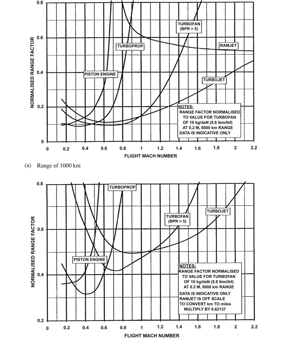
It is immediately apparent why the gas turbine so readily replaced the piston engine for most aircraft propulsion: the latter is only in contention at low Mach numbers, below around 0.3. This is primarily because propulsion power requirements increase rapidly with Mach number. The weight and frontal area of a piston engine increase far more rapidly with output power than they do for the gas turbine. The immense importance of these factors at high flight speed is quantified by the range factor diagram.
Above 0.3 Mach number the weight and frontal area considerations mean the turboprop takes over from the piston engine as the optimum power plant. It has better fuel consumption than a turbojet or turbofan, due to a high propulsive efficiency, achieving thrust by a high mass flow of air from the propeller at low jet velocity. Above 0.6 Mach number the turboprop in turn becomes uncompetitive, due mainly to higher weight and frontal area. In addition, high propeller tip speeds required are a difficult mechanical design issue, and the high tip relative Mach numbers create extreme noise.
Above 0.6 Mach number the turbofan and turbojet compete, the optimum choice depending on the application. The turbofan has a better SFC than the turbojet, but at the expense of worse specific thrust and hence weight and frontal area. Increasing bypass ratio provides the following engine tradeoffs:
• The capability for reverse thrust improves
• Weight per unit thrust increases
• Frontal area per unit thrust increases
• The number of LP turbine stages to drive the fan increases rapidly
• The cost per unit of thrust increases
• Auxiliary power and bleed offtake have a more powerful detrimental effect upon performance
The high bypass ratio engine is most competitive at flight Mach numbers of approximately 0.8, whereas at 2.2 Mach number the ideal bypass ratio is less than 1 and a turbojet becomes increasingly competitive.
Above about 2.0 Mach number the specific thrust of the ramjet becomes even better than that of a turbojet; however, it has poorer specific fuel consumption. The impact of this on range factor is shown on Figure 1–23. The low engine frontal area and weight resulting from the high specific thrust dominates at low range and high Mach number where the ramjet becomes the most competitive power plant. Also applications to date requiring this flight regime have been missiles and hence the lower unit cost of the ramjet is beneficial. For turbojet mechanical integrity the compressor delivery temperature must be kept to below approximately 950 K, hence above 2.5 flight Mach number there is very little room for compressor temperature rise.
The other possible power plant is a rocket, which is beyond the scope of this discussion.
Shaft-Powered Aircraft—Turboprops and Turboshafts
This section describes the requirements of shaft-powered aircraft, while the next section covers thrust propelled aircraft. The term turboprops usually refers to gas turbine engines that provide shaft power to drive a propeller for fixed wing aircraft propulsion. Those providing power for a rotary wing aircraft, or helicopter, are referred to as turboshafts.
Comparison of Propulsion Requirements of Shaft Power and Thrust Propelled Aircraft
The equivalent thrust and equivalent SFC of a turboprop may be calculated, allowing first cut comparisons of thrust and shaft power engines for a given application. The small amount of thrust available in a turboprop exhausts into an equivalent shaft power. This may be added to the delivered shaft power to get a total equivalent shaft power, and a corresponding SFC may be defined.
Major Classes of Shaft Powered Aircraft
Table 1–4 presents the major classes of shaft powered aircraft together with examples of actual aircraft and the engines utilized. Figure 1–25 presents key and interesting characteristics of these aircraft classes using the items from Table 1–4. Aircraft takeoff weight, range, maximum speed, and number of seats are plotted versus required power.
TABLE 1–4
Major Categories of Turboprop/Turboshaft Aircraft
| Item | Aircraft Type | Examples of Aircraft | Engines Utilized | Total Shaft Power (KW) |
| 1 | Light aircraft, piston engines | Piper Warrior II Beech Bonanza |
1 × TL 0320-133G flat twin 1 × TC 10 520 BB flat 6 |
120–220 |
| 2 | Business/executive Turboprop |
Piper Cheyenne 400 Cessna Caravan Dornier 228-100 |
2 × Garrett TPE331 1 × PW PT6A-114 2 × Garrett TPE331 |
500–1200 |
| 3 | Commuter/regional Transport turboprop |
BAE Jetstream 41 Shorts 330 BAe ATP Fokker 50 |
2 × Garrett TPE331 2 × PW PT6A-45R 2 × PW 126A 2 × PW 125B |
1800–4000 |
| 4 | Light helicopter, piston engines | Robinson R22 Schweizer 300C |
1 × TL 0-32-132C flat 4 1 × TL H10-360-DIA |
120–170 |
| 5 | Light helicopter, turboshaft engines | Bell-Jetranger III Bell 406 |
1 × Allison 250-C20J 1 × Allison 250-C30R |
300–500 |
| 6 | Multirole medium helicopter | Sikorsky S-70A (Black Hawk) Westland/Augusta EH101 |
2 × GE T700-700 3 × GE T700-401A, or 3 × RR/TM RTM322 |
2300–3500 |
| 7 | Heavy lift helicopter | Sikorsky H53E Boeing Chinook CH-47 |
3 × GE T64-416 2 × TLT55-712 |
6500 10,000 |
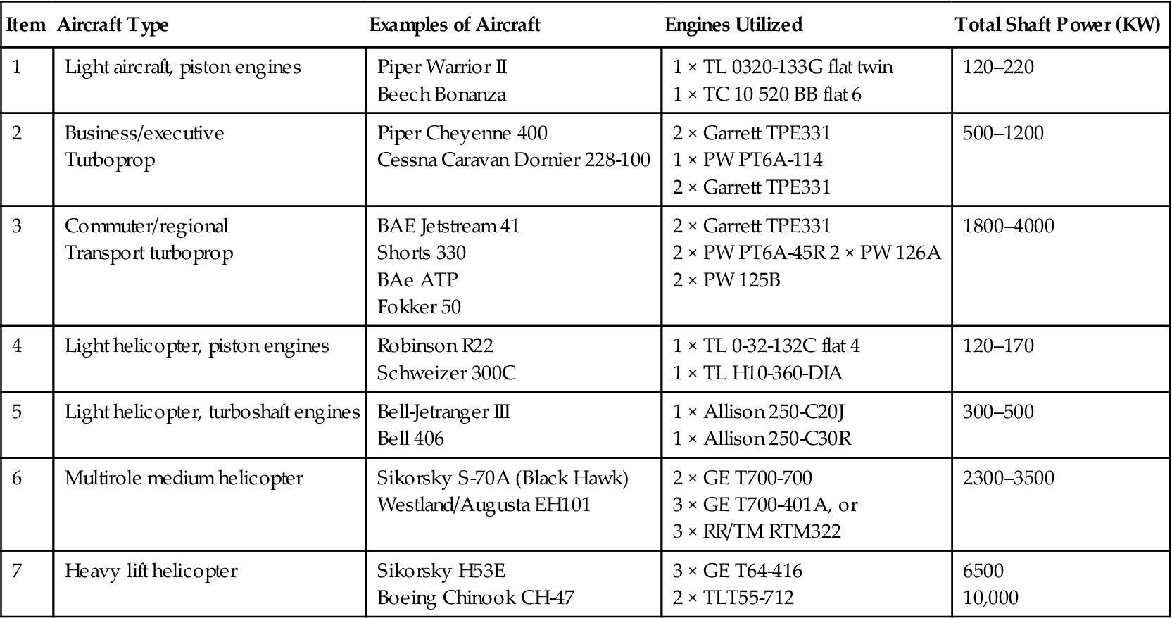
TL =Textron Lycoming; GE = General Electric; TC = Teledyne Continental;
RR = Rolls Royce; PW = Pratt & Whitney; BAe = British Aerospace
To convert kW to hp multiply by 1.341.
(Source: Rolls Royce.)
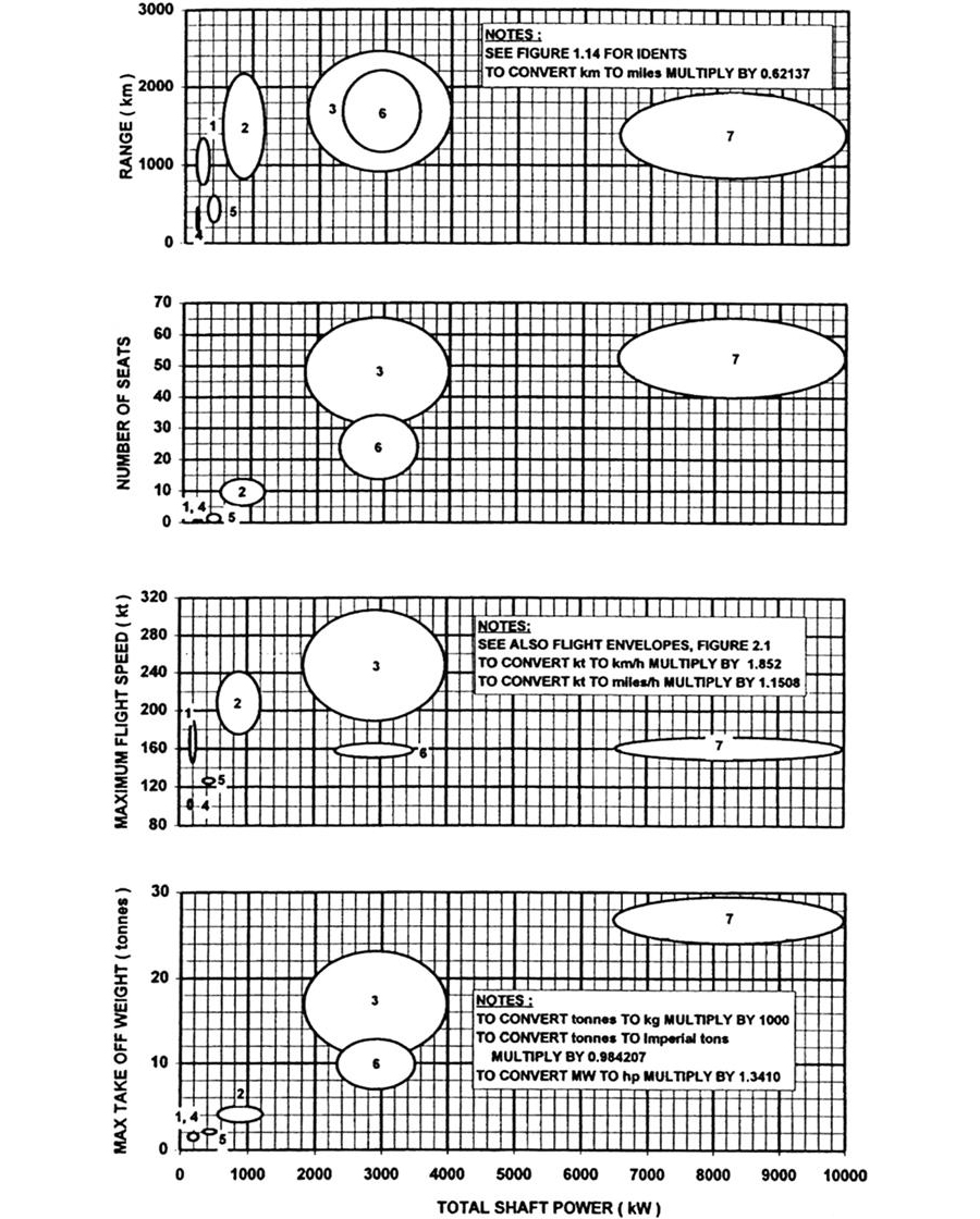
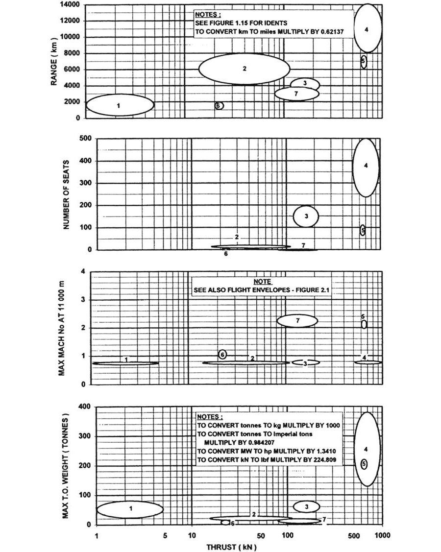
Fixed Wing Aircraft (Items 1, 2, and 3, Table 1–4)
Light aircraft are often privately owned, and used for short range transport or recreation. The business/executive turboprop is usually owned corporately to give flexibility in transporting executives. The commuter, or regional, transport turboprop is operated by commercial airlines on routes of moderate range, where the reduction in journey time offered by thrust aircraft would be of minimal benefit.
The piston engine now has only a few applications in the aircraft industry, one being for light aircraft with top speeds of less than 200 kt (0.30 Mach number). The piston engine is only competitive at such low flight speeds.
For the flight speeds and ranges demanded by business and commuter aircraft the range factor diagrams show the turboprop to be more competitive. Also at the engine powers above 250 kW the gas turbine is clear of the worst of the small-scale effects.
Engines are almost always of free power turbine configuration with a single spool or occasionally a two spool gas generator. Compressors are either centrifugal or axicentrifugal as this minimizes cost; efficiency is reasonably competitive with axial compressors at such low flow levels, and because frontal area is not critical at the moderate flight speeds involved. Pressure ratio is usually in the range 7:1–10:1. Axial flow turbine systems are employed with SOT levels of between 1250 and 1450 K. Above 1350 K, rotor blade cooling is employed. The choice of pressure ratio reflects a compromise between a lower value reducing the cost and weight of the compression system, and a higher value improving SFC and specific power if compressor efficiency is maintained.
Rotary Wing Aircraft (Items 4, 5, 6, and 7, Table 1–4)
Here the key criteria in order of importance are:
2. Part power SFC, as maximum power will either be sized for hot day operation, or for a multi-engine helicopter the engine failure case
4. Engine frontal area is not particularly significant due to the low flight speeds and “buried” installation
To minimize weight some small turboshafts are single spool, which is possible because rotor pitch may be varied to change load at constant speed. For medium turboshaft helicopters the engine configuration is as per the turboprop engines described above. Levels of pressure ratio and SOT are up to around 17:1 and 1500 K, respectively, the latter requiring turbine blade cooling. This pressure ratio is the optimum for specific power. At the largest engine size fully axial compressors are employed. Occasionally recuperated cycles have been considered for long-range helicopters to minimize fuel weight, though none have come to fruition. This is primarily due to the increased engine cost, weight and volume, and reliability concerns. Piston engines are used only at the lowest power levels. Figure 1–24.
Thrust Propelled Aircraft—Turbofans, Turbojets, and Ramjets
Major Classes of Thrust Propelled Aircraft
Table 1–5 presents the major classes of thrust propelled aircraft, together with examples of actual aircraft and the engines utilized. Figure 1–25 presents characteristics of these aircraft classes using the item numbers from Table 1–5.
TABLE 1–5
Major Classes of Thrust Propelled Aircraft
| Item | Aircraft Type | Examples of Aircraft | Engines Utilized | Total Thrust ISA SLS TIO (kN) |
| 1 | Unmanned Vehicle Systems (UVS) | Beech MOM 107B Target Drone IMI Delilah Decoy GD BGM-109 Tomahawk long range cruise missile |
1 × MT TR160-2-097 TJET 1 × NPT 151 TJET 1 × WI F107-WR-103 TFAN |
1–5 |
| 2 | Business/executive jet | Swearingen SJ30 Gulfstream IV BAe 125 Series 800 |
2 × WI/RR FJ44 TFANS 2 × RR TAY 611-8 TFANS 2 × GT TFE731-5R-1H |
15–120 |
| 3 | Short-medium range civil transport | Fokker 100 Boeing 737-400 Airbus A320 |
2 × RR TAY 620 TFANS 2 × CFM56-3B-2 TFANS 2 × IAE V2500 A1 TFANS or 2 × CFM56-5 TFANS |
120–220 |
| 4 | Long range civil transport | Airbus A310 Boeing 747 400 |
2 × PW4152 TFANS or 2 × GE CF6-80C2-A8 4 × PW4056 TFANS or 4 × GE CF6-80C2 TFANS or 4 × RR RB211-524H TFANS |
500–1000 |
| 5 | Supersonic civil transport | BAe/Aerospatiale Concorde | 4 × SNECMA/RR Oympus 593 TJETS | 600–700 |
| 6 | Military trainer/light attack aircraft | BAe Hawk Aermachi MB-339C |
1 × RR/TM Adour TFAN 1 × RR Viper TJET |
20–25 |
| 7 | Advanced military fighter | General Dynamics F16 Falcon Panavia Tornado (BAe, MBB, Aeritalia) McDonnell Douglas F15C |
1 × GE F110-GE-100 TFAN or 1 × PW F100-PW-220 TFAN 2 × TU R8199-34R TFANS 2 × PW F100-PW220 TFANS |
80–220 |
| 8 | Ramjet propelled missiles | BAe Sea Dart (ship to air) BAe Bloodhound (gr. to air) |
1 × RR TODINHOR 1 × RR |
N/A N/A |
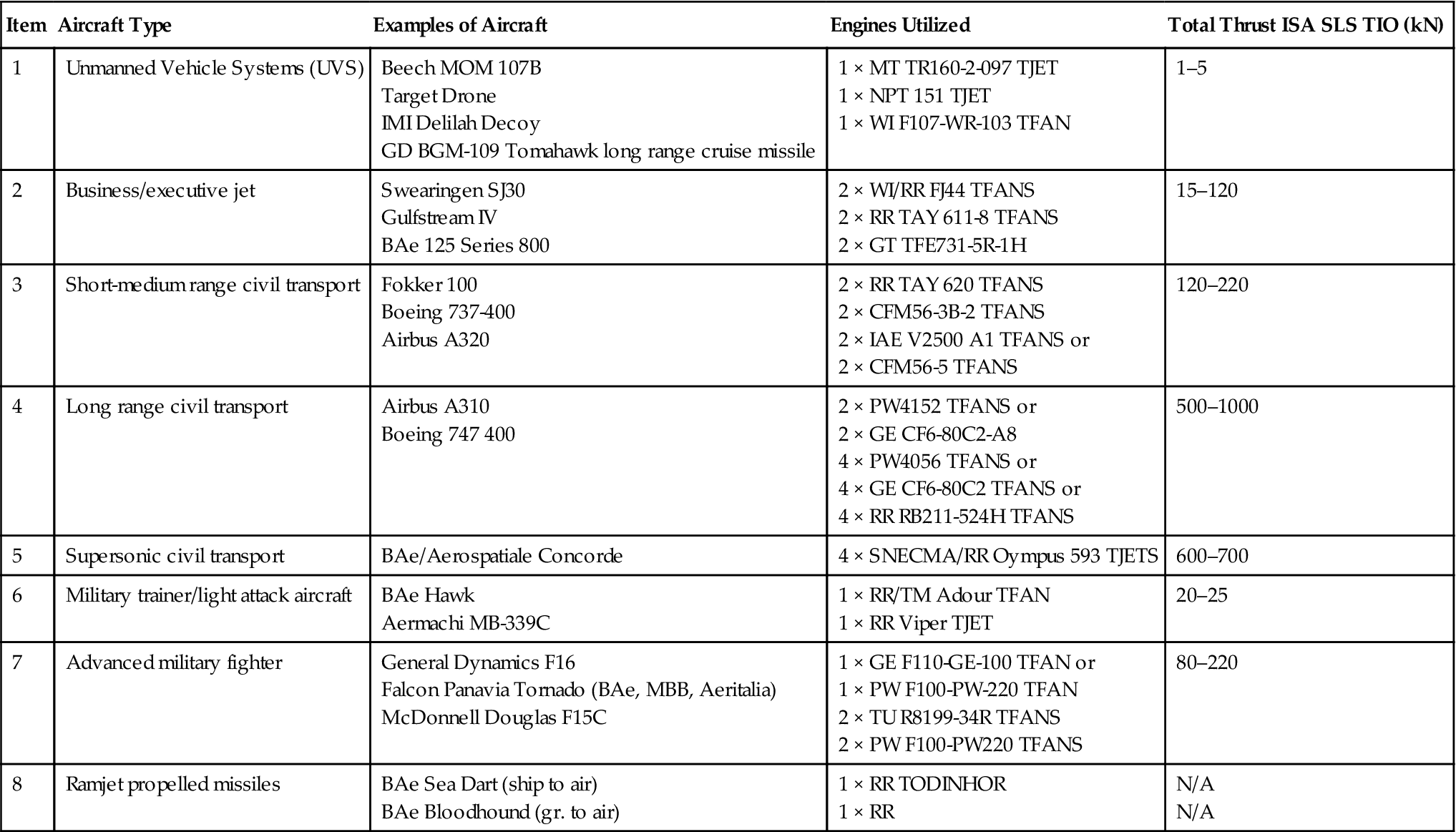
WI = Williams International; RR = Rolls Royce; CFM = GE/SNECMA Joint Venture; MT = Microturbo;
NPT = Noel Penny Turbines; IAE = International Aero Engines; IMI = Israeli Military Industries;
BAe = British Aerospace; TU = Turbo Union; PW = Pratt & Whitney; GE = General Electric; GT = Garrett;
TM = Turbomeca.
To convert kN to lbf multiply by 224.809.
(Source: Rolls Royce.)
Unmanned Vehicle Systems (Item 1, Table 1–5)
Unmanned vehicle systems include aircraft such as target and reconnaissance drones, decoys used by military aircraft to divert threats, and long range cruise missiles.
For expendable target drones and decoys the highest priority is minimum unit cost. A Mach number of at least 0.8 is usually required, with only a low range requirement. Single spool turbojets are usually used, often with centrifugal compressors because of their low cost and the low mass flow rates. Any increased weight and frontal area are accepted. Engine pressure ratios are usually between 4:1 and 8:1 as a compromise between low values favoring weight and frontal area, and high values favoring SFC and specific thrust. Low SOT levels of around 1250 K avoid the need for turbine cooling (and also give better SFC for a turbojet). Both axial and radial turbines are used.
The long range required by cruise missiles means that they fit the turbofan regime with SFC a key issue, though engine size and cost are also important as the vehicle must be transported and is expendable. Medium bypass ratio turbofans are employed, with centrifugal compressors. Indicative cycle parameters are 1.5:1 bypass ratio, 10:1 pressure ratio, and 1250 K SOT.
Subsonic Commercial Aircraft and Military Trainer (Items 2, 3, 4, and 6, Table 1–5)
Business/executive jets and civil subsonic transports all have range and flight Mach number requirements fitting the turbofan regime. They all use multi-spool gas generators with axial flow turbomachinery (except at the smallest sizes) and sophisticated turbine blade cooling for the best SFC. The pressure ratio is selected from cycle charts to give the best cruise SFC for the given SOT.
The highest bypass ratio for an engine in production at the time of writing is 8.5:1. At ISA SLS takeoff, advanced engines utilize a fan pressure ratio of around 1.8:1, and overall pressure ratio exceeds 40:1. The corresponding SOT is around 1650 K, rising to over 1750 K on a hot day. At ISA cruise overall pressure ratio is around 10% lower, and SOT around 1400 K. The highest overall pressure ratio in the flight envelope is around 45:1 at the top of climb. For lower technology engines bypass ratio is nearer to 4:1. At ISA SLS takeoff, fan pressure ratio is approximately 1.8:1 and overall pressure ratio 25:1, with SOT around 1525 K. At cruise, pressure ratio is around 10% lower, and SOT around 1350 K.
Military trainer aircraft are again in the subsonic regime, but range requirements are shorter and unit cost very important. Here turbojets and turbofans compete.
Supersonic Civil Transport and Advanced Military Fighter (Items 5 and 7, Table 1–5)
The only engines viable here are turbojets, or turbofans with a bypass ratio of less than 1:1. Multi-spool configurations with all axial turbomachinery are used for maximum efficiency and minimum frontal area. All engines have reheat systems that are employed at key points in the operational envelope.
For the limited civil applications to date, such as Concorde, and U.S. and Russian development programs, afterburning turbojets have been utilized. Takeoff SOT exceeds 1600 K, though higher values might be chosen for more modern engine designs. Pressure ratios of around 14:1 have been employed to minimize weight, and because higher values are not practical due to the high compressor delivery temperature at high flight Mach number. In addition, this value is the optimum for a pure turbojet specific thrust around a Mach number of 1.0, and also for reheated operation at 2.2 Mach number. At this flight speed the reheat fuel is burned at a high enough pressure that SFC is little worse than for a pure jet, though thrust is significantly higher. Studies for future applications encompass variable cycles, where higher bypass ratio minimizes noise and SFC during subsonic overland flight.
Advanced military fighters use low bypass ratio afterburning turbofans, with maximum SOT exceeding 1850 K and pressure ratio around 25:1. Combustor inlet temperature approaches 900 K. Future engine designs are considering SOT levels of 2000–2100 K, with combustor inlet temperatures nearer 1000 K, requiring ceramic materials. Again, engine designs with variable cycles have been proposed, to achieve higher bypass ratio to improve SFC at low flight Mach number.
One other military aircraft application is for short/vertical takeoff/landing (VTOL or STOVL), operational forms of which have utilized two main approaches. The U.K./U.S. Harrier has a fixed geometry turbofan (RR Pegasus) with four rotatable propelling nozzles, two for the core stream and two for the bypass. In contrast, Russian Yakalov aircraft have used separate vertically mounted lift jets. Future variable cycle engines could be beneficial for a Harrier type approach, providing additional bypass air for jet borne flight.
Ramjet Propelled Missiles (Item 8, Table 1–5)
At Mach numbers in excess of 2.5 the ramjet is the ideal powerplant. Combustion temperatures approach the stoichiometric value, where all oxygen is used. This ranges from 2300 to 2500 K, depending on inlet temperature and hence flight Mach number, and is feasible as there are no stressed turbine blades to consider. At these Mach numbers the only competitor engine is a rocket. Starting a ramjet requires a short duration booster rocket, to accelerate the vehicle to a Mach number where operation is possible.
Air to air missiles to date have been almost entirely rocket powered, as this better suits the requirement of high thrust for a short duration. However, experimental ramjet versions have been produced, particularly in France and the former USSR. Several current proposals involve ramjets, as air-to-air missile range requirements increase.
Surface to air missiles with ramjets have seen production, such as the U.K. “Bloodhound,” as range requirements are more suitable. A typical mission would be launch, climb to around 20,000 m, followed by a loiter phase and then attack. The distance covered would be around 50 km.
Auxiliary Power Units (APUs)
Aircraft APUs have normally fulfilled several functions in an aircraft, namely:
• Supply of cooling air for aircraft secondary systems, particularly when at ground idle in hot climates
• Supply of electrical power when main engines are shut down, including for ground checkout of aircraft systems
These functions give an aircraft self sufficiency when on the ground. In addition an APU will be required to fire up at altitude in case of main engine flame out, to power electrical systems—vital for fly by wire aircraft—and if at low flight Mach number to provide crank assistance to help restart the engines.
Until recently, new developments have been rare, but APU sophistication is now increasing to match that of recent aircraft, where APU operation is becoming less intermittent. For civil applications APU requirements may now include operation in all regions of the flight envelope, and for military aircraft advanced systems with start times as low as a second. A current typical start time is around 6 seconds at 15,000 m. There are occasional studies on the benefits of permanent running power units that avoid compromising the design of the propulsion engines by power and bleed offtake.
Historically the main requirements for APUs have been:
Gas Turbines Versus Piston Engines
APUs for aircraft are almost exclusively simple cycle gas turbines. Power density in terms of weight and volume per unit of shaft output power are vastly superior to a piston engine, around 4.4 kW/kg and 8 MW/m3. This effectively makes a piston engine impractical, despite its lower unit cost. Fuel consumption becomes a secondary issue where operation is intermittent.
APU Power Requirements of Major Aircraft Classes
The output power range of APUs is between 10 kW and 300 kW, with bleed supplied requiring additional turbine power. Table 1–6 presents specific examples of APUs employed in production aircraft.
TABLE 1–6
Auxiliary Power Unit (APU) Examples and Applications
| Model | Configuration | Application | Power (kW) |
| Turbomach T-62T-40-8 | Single shaft: 1 Stage centrifugal compressor Reverse flow annular combustor 1 Stage radial turbine |
Jet fuel starter General Dynamics F16 Fighter |
190 |
| Allied Signal 131-9(D) | Single shaft: 1 Stage centrifugal compressor 2 Stage axial turbine 1 Stage centrifugal load compressor |
Bleed, E.G. engine start Electrical power ENV conditioning McDonnell Douglas MD90 |
300/100 |
| Allied Signal 331-500B | Single shaft: 2 Stage centrifugal compressor Reverse flow annular combustor 2 Stage axial turbine 1 Stage centrifugal load compressor |
Bleed, E.G. engine start Electrical power Boeing 777 |
850/170 |
| APIC APS 3200 |
Single shaft: 1 Stage centrifugal compressor Reverse flow annular combustor 2 Stage axial turbine 1 Stage centrifugal load compressor |
Electrical power Oil and fuel pumps Airbus A321 |
385/90 |
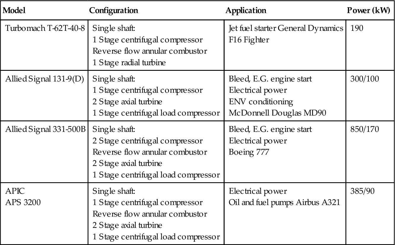
All data is indicative.
Where two powers are shown the higher figure includes the load compressor drive power.
To convert kW to hp multiply by 1.3410.
To convert kg to lb multiply by 2.2046.
APIC–Auxiliary Power International Company.
(Source: Rolls Royce.)
APU Configurations
For all configurations centrifugal compressors are used exclusively and often radial inflow turbines, even occasionally combined as a monorotor to minimize cost. SOT levels are typically 1250 to 1260 K to minimize the need for turbine cooling. Pressure ratio is generally between 4:1 and 8:1, though the trend is towards higher levels.
The most common forms of APU provide high-pressure air to the main engine mounted air turbine starter. These are referred to as pneumatic APUs. Air must usually be supplied at around five or more times ambient pressure, with the APU sized to enable hot day main engine starting. The most common pneumatic APU is a single shaft gas turbine with integral bleed. Here the engine is of single spool configuration but with the pneumatic air supply bled off from compressor delivery. This is the simplest unit and hence has the lowest cost. Also generators or pumps may be driven off the spool to provide electrical or hydraulic power.
Single shaft gas turbines driving a centrifugal load compressor, as well as application pumps or generator are growing in popularity. This configuration has the highest power output per unit mass and volume, though it is of higher cost.
A small number of APUs apply torque directly to the main engine HP shaft via its gearbox and a clutch, rather than supplying high-pressure air. These are termed jet fuel starters. In this instance the APU is often of free power turbine configuration to provide an adequate partial speed torque characteristic.