
Maintenance, Repair, and Overhaul
Abstract
Maintenance, repair, and overhaul make up a major component of the cost per fired hour for a gas turbine system. The initial specification sets the tone for the end user’s experience with that turbine. Systems and accessories can be specified that will help raise the turbine’s TBOs and component lives. The end user’s negotiated warranty, service, and training package also has the ability to improve matters in both the operator’s and the turbine’s life. Repair and overhaul are inevitable, as the turbine ages, but this component of cost per fired hour can be minimized if the end user is proactive in terms of strategy in this vein. Maximized availability, or “up time,” and the troubleshooting process (i.e., how easy it is to troubleshoot a machine) depends largely on the type of maintenance philosophy applied during the machine’s operational life. This basic philosophy also affects the monitoring process.
Keywords
Maintenance; maintenance information systems; audit procedures; audit planning; monitoring process; training; costs per fired hour
“Learn from the mistakes of others, you’ll never live long enough to make them all yourself.”
—Old Pilots’ saying
. . . but. . . .
“You’re never too old to become younger.”
—Mae West
Maintenance,1 repair, and overhaul make up a major component of the cost per fired hour for a gas turbine system. The initial specification sets the tone for the end user’s experience with that turbine. Systems and accessories can be specified that will help raise the turbine’s TBOs and component lives (see Chapter 9, ECMS, and Chapter 10, Performance, Performance Testing, and Performance Optimization). The end user’s negotiated warranty, service, and training package (see Chapter 14, The Business of Gas Turbines) also has the ability to improve matters in both the operator’s and the turbine’s life. Repair and overhaul are inevitable, as the turbine ages; however, this component of cost per fired hour can be minimized if the end user is proactive in terms of strategy in this vein.
Operating and Maintenance Strategies
Maximized availability, or “up time,” and the troubleshooting process (i.e., how easy it is to troubleshoot a machine) depend largely on the type of maintenance philosophy applied during the machine’s operational life. This basic philosophy also affects the monitoring process.
Equally, the strategies and philosophy behind a turbine’s selection play a key role in defining maintenance requirements. Unfortunately, a number of operators never link maintenance philosophy and troubleshooting to an appropriate extent. Therefore, they either leave themselves wide open for disastrous repair bills or spend more than they need to on maintenance.
This is poor maintenance management, as it can increase turbine system costs per fired hour. This section describes three main strategies appropriate for all rotating machinery, including gas turbine systems. A choice of these strategies should not be made by the manufacturer. It needs to fit the operator’s specific application and comfort level. The manufacturer’s resources and technical expertise should be utilized to support the decision process by providing relevant information.
The operator, typically, proceeds as follows. Basic goals are itemized. The highest priority is to maximize production. Optimizing production per unit of energy is part of that aim. Maximum availability and reliability (i.e., no unplanned downtime) are also critical. Operators want to minimize the maintenance, service, and repair costs.
Reactive Strategy
Too little maintenance results in unexpected failures and consequential major losses of production or customers. This approach is termed reactive strategy (or wait until something fails) and should be avoided on all machinery in critical applications.
Optimum maintenance strategy balances reasonable costs with maximum possible availability and reliability. The two most common main maintenance strategies employed by companies today are labeled predictive strategy and preventive strategy.
Predictive Strategy
Predictive maintenance strategies operate without a regular plan for service work or exchange of parts. A maintenance plan is set up only if there is proof of deterioration. Consequently, a company with a predictive strategy favors minimizing cost over maximizing use. Annual cost of this strategy may typically only average out to 1–2% of the prime equipment price.
With a predictive maintenance strategy, long-term plans generally involve some or all of the following.
Monitoring of operating data as follows:
• Gas path (mass flow, pressure head, efficiency)
• Water coolant (differential temperature)
• Oil analysis (water content, deterioration of anti-aging additives)
• Temperature monitoring of gas path, bearing oil.
• Incorporation of some of these parameters in a performance analysis (PA) system (see subsection in this chapter)
• Rotating speed or rpm of the different turbine rotors
• Incorporation of some of these parameters in an algorithm that is custom designed, usually by the original equipment manufacturer (OEM), to calculate life cycle usage in a life cycle assessment (LCA) system
Preventive Strategy
In contrast with predictive strategy, preventive strategy aims toward maximum safety against unexpected failures. The concept here is to predict the average lifespan of a part and replace it before the end of that lifespan. Annual cost therefore is higher (perhaps 8–10% of the prime equipment price) because of the higher numbers of spare parts that need to be purchased and warehoused.
Besides the effects of choice of maintenance strategy on the troubleshooting time and effort required, the application service the unit is in also has an effect. With increasingly tough environmental legislation that, in turn, demands maximum energy usage or recovery, power recovery (cogeneration) processes are increasing in number. The deregulation of the power industry results in the increase of small power producers, or SPPs (such as process plants that can use existing process fluids to assist in energy efficiency and cogeneration). So deregulation also serves to increase the number of SPPs.
Evolving Strategy in Land Versus Air Versus Marine Applications
About three decades ago, it was common for gas turbine users to talk about the number of operating hours their unit had been running. The mid-1970s saw the beginnings of change to the concept of “cycles of operation.”
The realization in aircraft engine application that sponsored that change was the acknowledgment that service factors on engines varied with mission profile and individual engine roles. The life (cycle) accumulation on the lead aircraft in aerobatic formation was up to 20 times less than that of the “followers'” engines. The pilots had to fidget with their power settings, back and forth, to stay the prerequisite distance from the leaders’ wingtips.
In land-based applications, people began to realize that a start and stop with a Solar Saturn (nominal 1100 HP) engine may cost as little as the equivalent of 3–5 hours of full load operation. However, a start and stop of a GE Frame 5 (nominal 25,000 HP) might cost that engine as much as 500 hours of its operational life.
Research commenced on developing algorithms for life cycle assessment (LCA). For engines built by OEMs that use a high degree of cooling, such as Rolls Royce, the only relevant parameters in their algorithms for specific models may be rpm (excursions) versus time. For engines that did not have as much cooling, a temperature parameter in the algorithm was in order.
The service bulletins (SBs) that evolved to reveal these algorithms were as a result of end-user pressure. The end-user community thus was able to get longer lives out of their most expensive gas turbine components. LCA was done with LCAC (life cycle assessment counters). Instrumentation and condition monitoring OEMs that specialized in LCAC, such as Vosper Thornycroft, UK (also called HSDE), soon began to be approved and “certified for retrofits” by a wide range of GT OEMs.
Before LCA, preventive maintenance charts used to state a schedule of mandatory inspections, component removals, and tasks at different “total operating hours accumulated” of a gas turbine. Now those charts might call up cycle (as measured by the LCA counters) numbers.
In the case of engines whose metallurgy places their stress levels under the stress endurance curve, operation may be “on condition” (as observed with borescopes and other nonintrusive means or as observed by a limited “opening up” at an HSI, or hot section inspection).
HSIs are conducted on all gas turbine applications, land, sea, or air. There may also be unscheduled, limited or otherwise “opening up” as prompted by alarming vibration readings, borescope observations, or other monitoring means.
Due to the variable nature of aircraft engine applications, the engine external features and the aircraft are inspected visually before every flight during a pilot “walk around.” Oil or hydraulic leaks may be observed at this stage. During the pilot’s “run up” on the tarmac prior to takeoff, problems with excessive temperatures and pressures may be observed, sometimes necessitating a “return to the gate.” ECMS are sufficiently sophisticated today that postflight analysts can tell which pilots like to “red line” their engines. Advancements in (air-to-ground) telemetry make it possible for ground staff to know which module of an aircraft engine they may want to “swap” when the aircraft next lands.
Because of their relative isolation (compared with ground applications), operators of air (say, a CF6-80C2) and marine (LM2500) gas turbines require a regular maintenance schedule that is far more exacting than their ground-based (LM2500) counterparts. This is particularly true if that land-based counterpart also runs at steady load (as in, for instance, power generation).
So aircraft engine operators (as legislated by the US FAA, the European JAA, or other international flying legislative authorities) must conduct exacting:
• Routine maintenance (after every flight, daily, or at some specified time)
• Routine inspections (such as HSIs at fixed intervals of cycles accumulated)
• Planned maintenance (if the engine is not an “on-condition” design) of varying complexity
For instance, the Pratt and Whitney JT 8D fleet that operates on a preventive maintenance philosophy (particularly with its earlier models) has to have “ESV1s” and “ESV2s” to bring it back to “zero time” condition. The list of work items, SBs both mandatory and optional, and “work, based on observed condition” for an ESV2 is far longer and more complex than for an ESV1. Other OEMs may have their own designation (other than ESV-) and stated intervals (in hours if it's an old fleet, or cycles if it has an LCA counter).
Of course, once one is talking about an “ESV1 or 2,” one is now into the “repair and overhaul” (R&O) phase of that gas turbine’s life. R&O is a highly specialized subdivision of overall maintenance. For the most part, it is distinguished from “regular and routine” maintenance in that many work items are not routine but “as needed” and “based on condition observed” only.
What follows is a summary of regular maintenance on an aeroengine. It provides a good template for all gas turbines, as land-based and marine gas turbines need the same basic functions checked. Exactly which instruments, features, and functions need checking and their frequency (daily, weekly, monthly, as needed) is spelled out in the maintenance manuals supplied with every gas turbine.
Maintenance2,3
,Maintenance covers both the work that is required to maintain the engine and its systems in an airworthy condition while installed in an aircraft (on-wing or line maintenance) and the work required to return the engine to airworthy condition when removed from an aircraft (overhaul or shop maintenance). On-wing maintenance is covered in this section.
Because many aspects of maintenance are subject to the approval of a recognized authority, it should be fully understood that the information given in this section is of a general nature and is not intended as a substitute for any official instructions.
The comprehensive instructions covering the actual work to be done to support scheduled maintenance and unscheduled maintenance are contained in the aircraft maintenance manual. Both this publication, and the aircraft maintenance schedule mentioned later, are based on manufacturers’ recommendations and are approved by the appropriate airworthiness authority.
The maximum time an engine can remain installed in an aircraft (engine life) is limited to a fixed period agreed between the engine manufacturer and airworthiness authority. On some engines this period is referred to as the time between overhaul (TBO) and on reaching it the engine is removed for complete overhaul.
Because the TBO is actually determined by the life of one or two assemblies within the engine, during overhaul, it is generally found that the other assemblies are mechanically sound and fit to continue in service for a much longer period. Therefore, with the introduction of modular engines and the improved inspection and monitoring techniques available, the TBO method on limiting the engine’s life on-wing has been replaced by the “on-condition” method.
Basically this means that a life is not declared for the total engine but only for certain parts of the engine. On reaching their life limit, these parts are replaced and the engine continues in service, the remainder of the engine being overhauled “on condition.” Modular constructed engines are particularly suited to this method, as the module containing a life-limited part can be replaced by a similar module and the engine returned to service with minimum delay. The module is then disassembled for life limited part replacement, repair, or complete overhaul as required.
On-Wing Maintenance
On-wing maintenance falls into two basic categories: scheduled maintenance and unscheduled maintenance.
Scheduled Maintenance
Scheduled maintenance embraces the periodic and recurring checks that have to be effected in accordance with the engine section of the appropriate aircraft maintenance schedule. These checks range from transit items, which do not normally entail opening cowls, to more elaborate checks within specified time limits, usually calculated in aircraft flying hours and phased with the aircraft check cycle.
Continuous “not-exceed-limit” maintenance, whereby checks are carried out progressively and as convenient within given time limits rather than at specific aircraft check periods, has been widely adopted to supersede the check cycle. With the progressive introduction of condition monitoring devices of increased efficiency and reliability, a number of traditionally accepted scheduled checks may become unnecessary. Extracts from a typical maintenance schedule are shown in Table 12–1.
TABLE 12–1
A Typical Maintenance Schedule (Extracts)
| Item | Not Exceed Limit | Requirement |
| Engine oil tank | Flight termination | Check oil level. Replenish as necessary. Record amount taken |
| Cowls | Transit | Check the pod cowls for damage and external evidence of fuel and oil leaks |
| Caps and access panels | Transit | Check secure |
| Engine intake | Transit | Check clear. Free from damage and loose objects |
| Turbine and exhaust collector | Transit | Visually inspect for signs of damage and metal deposits |
| Engine intake | 25 hours | Visually inspect front of engine through air intake for signs of damage paying particular attention to intake guide vanes and leading stage rotor blades |
| Turbine and exhaust collector | 25 hours | Visually inspect L.P.2 turbine blades, nozzle guide vanes and mixer unit for cracking and damage by viewing from rear using a strong spot light |
| Fuel filter | 125 hours | Drain sample and check for water contamination |
| Magnetic chip detector | 200 hours | Remove and inspect |
| Igniter plugs | 200 hours | Audibly check operation |
| Oil pressure filter | 600 hours | Check and clean/renew filter element |
| Fuel filter | 800 hours | Remove filter element, check and renew |
(Adapted, with permission, from Rolls Royce, The Jet Engine, 1986, Rolls Royce Plc: UK.)
Unscheduled Maintenance
Unscheduled maintenance covers work necessitated by occurrences that are not normally related to time limits, e.g., bird ingestion, a strike by lightning, a crash, or heavy landing. Unscheduled work required may also result from malfunction, troubleshooting, scheduled maintenance, and occasionally manufacturer’s specific recommendations. This type of maintenance usually involves rectification adjustment or replacement.
Condition Monitoring
Condition monitoring devices must give an indication of any engine deterioration at the earliest possible stage and also enable the area or module in which deterioration is occurring to be identified. This facilitates quick diagnosis that can be followed by scheduled monitoring and subsequent programmed rectification at major bases, thereby avoiding in-flight shutdown, with resultant aircraft delay, and minimizing secondary damage. Monitoring devices and facilities can be broadly categorized as flight deck indicators, in-flight recorders, and ground indicators.
Flight Deck Indicators
Flight deck indicators are used to monitor engine parameters such as thrust or power, rpm, turbine gas temperature, oil pressure, and vibration. Other devices, however, may be used and these include:
• Accelerometers for more reliable and precise vibration monitoring
• Radiation pyrometers for direct measurement of turbine blade temperature
• Return oil temperature indicators
• Remote indicators for oil tank content
• Engine surge or stall detectors
• Rub indicators to sense eccentric running of rotating assemblies
In-Flight Recorders
Selected engine parameters are recorded, either manually or automatically, during flight. The recordings are processed and analyzed for significant trends indicative of the commencement of failure. An in-flight recording device that may be used is the time/temperature cycle recorder. The purpose of this device is to accurately record the engine time spent operating at critical high turbine gas temperatures, thus providing a more realistic measure of “hot-end” life than that provided by total engine running hours.
Automatic systems known as aircraft integrated data systems (A.I.D.S.) are able to record parameters additional to those normally displayed, e.g., certain pressures, temperatures, and flows.
Many of the electronic components used in modern control systems have the ability to monitor their own and associated component operation. Any fault detected is recorded in its built-in memory for subsequent retrieval and rectification by the ground crew. On aircraft that feature electronic engine parameter flight deck displays certain faults are also automatically brought to the flight crew’s attention.
Ground Indicators
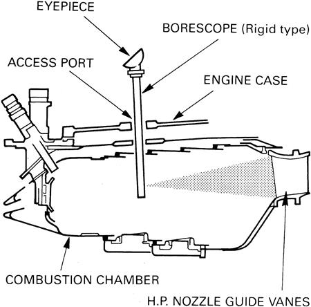
The devices used or checked on the ground, as distinct from those used or checked in flight, may conveniently be referred to as ground indicators; this title is also taken to embrace instruments used for engine internal inspection.
Internal viewing instruments can be either flexible or rigid, designed either for end or angled viewing and, in some instances, adaptable for still or video photography that may be linked to closed circuit television. These instruments are used for examining and assessing the condition of the compressor and turbine assemblies, nozzle guide vanes (Figure 12–1), and combustion system, and can be inserted through access ports located at strategic points in the engine main casings.
The engine condition indicators include magnetic chip detectors, oil filters and certain fuel filters. These indicators are frequently used to substantiate indications of failures shown by flight deck monitoring and in-flight recordings. For instance, inspection of the oil filters and chip detectors can reveal deposits from which experienced personnel can recognize early signs of failure. Some maintenance organizations progressively log oil filter and magnetic chip detector history and catalogue the yield of particles. Fuel filters may incorporate a silver strip indicator that detects any abnormal concentration of sulfur in the fuel.
Maintenance Precautions
During engine maintenance, it is necessary to observe certain precautions. The ignition system is potentially lethal and, therefore, before any work is done on the high energy ignition units, igniter plugs or harness, the low tension supply to the units must be disconnected and at least 1 minute allowed to elapse before disconnecting the high tension lead. Similarly, before carrying out work on units connected to the electrical system, the system must be made safe, either by switching off power or by tripping and tagging appropriate circuit breakers. With some installations, the isolation of certain associated systems may be required.
When the oil system is being replenished, care must be taken that no oil is spilled. If any oil is accidentally spilled, it should be cleaned off immediately as it is injurious to paintwork and to certain rubber compounds such as could be found in the electrical harnesses. Oil can also be toxic through absorption if allowed to come into contact with the human skin for prolonged periods. Care should be taken not to overfill the oil system; this may easily occur if the aircraft is not on level ground or if the engine has been stationary for a long period before the oil level is checked.
Before an inspection of the air intake or exhaust system is made it must be ascertained that there is no possibility of the starter system being operated or the ignition system being energized.
A final inspection of the engine, air intake and exhaust system must always be made after any repair, adjustment or component change, to ensure that no loose items, no matter how small, have been left inside. Unless specific local instructions rule otherwise, air intake and exhaust blanks or covers should be fitted when engines are not running.
Troubleshooting
The procedure for locating a fault is commonly referred to as troubleshooting, and the requirement under this procedure is for quick and accurate diagnosis with the minimum associated work and the prevention of unnecessary unit or engine removals.
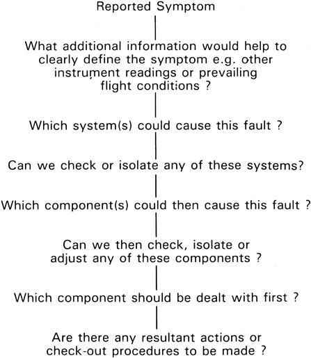
The basic principle of effective troubleshooting is to clearly define and interpret the reported symptom and then proceed to a logical and systematic method of diagnosis (Figure 12–2).
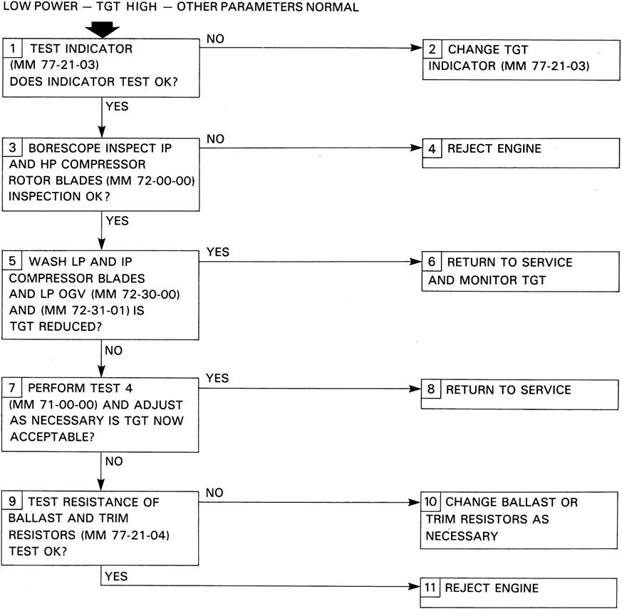
The reported symptom will frequently originate from flight deck instrument readings and, unless it is apparent from supporting information that the readings are genuine, instrumentation should be checked before proceeding further. Similarly, quick elimination checks should normally be undertaken before more involved tasks. The manufacturers’ maintenance manual contains troubleshooting information, usually in chart form and Figure 12–3 shows a typical example.
The progressive introduction of improved and more reliable condition monitoring devices will have considerable influence on accepted troubleshooting practice, since to a large extent these devices are designed to pin-point, at an early stage, the specific system or assembly at fault. The development of suitable test sets could eventually eliminate the need for engine ground testing after troubleshooting.
Adjustments
There are usually some adjustments that can be made to the engine controlling the fuel trimming devices. Typical functions for which adjustment provision is normally made include idling and maximum rpm, acceleration and deceleration times, and compressor air bleed valve operation.
Adjustment of an engine should be made only if it is quite certain that no other fault exists that could be responsible for the particular condition. The maintenance manual instructions relative to the adjustment must be closely adhered to at all times. In many instances, subject to local instructions, a ground adjustment can be made with the engine running.
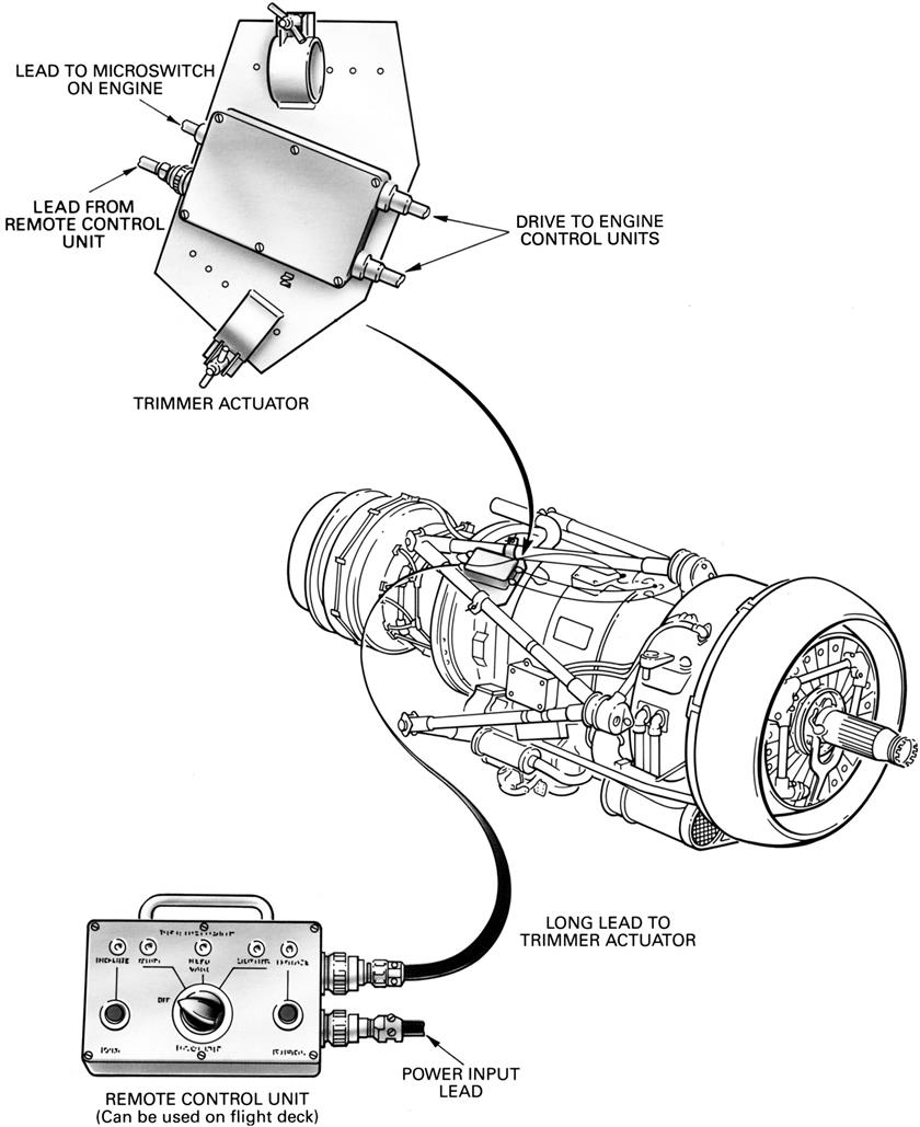
Adjusters are usually designed with some form of friction locking (Figure 12–4) that dispenses with locknuts, lock-plates, and looking wire. On some engines, provision is also made for fitting remote adjustment equipment (Figure 12–5) that permits adjustment to be made during ground test with the cowls closed, the adjustment usually being made from the flight deck.

Ground Testing
The basic purpose of engine ground testing is to confirm performance and mechanical integrity and to check a fault or prove a rectification during troubleshooting. Ground testing is essential after engine installation, but scheduled ground testing may not normally be called for where satisfactory operation on the last flight is considered to be the authority or acceptance for the subsequent flight. In some instances, this is backed up by specific checks made in cruise or on approach and, of course, by evidence from flight deck indicators and recordings.
For economic reasons and because of the noise problem, ground testing is kept to a minimum and is usually only carried out after engine installations, during troubleshooting, or to test an aircraft system. With the improved maintenance methods and introduction of system test sets that simulate running conditions during the checking of a static engine, the need for ground testing, particularly at high power, is becoming virtually unnecessary.
Before a ground test is made, certain precautions and procedures must be observed to prevent damage to the engine or aircraft and injury to personnel.
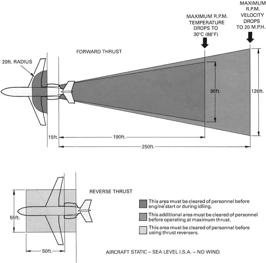
Because of the mass of air that will be drawn into the intake and the resultant high velocity and temperature of the exhaust gases during a ground test, danger zones exist at the front and rear of the aircraft. These zones will extend for a considerable distance, and a typical example is shown in Figure 12–6. The jet efflux must be clear of buildings and other aircraft. Personnel engaged in ground testing must ensure that any easily detachable clothing is securely fastened and should wear acoustic earmuffs.
The aircraft should be headed into wind and positioned so that the air intake and exhaust are over firm concrete, or a prepared area that is free from loose material and loose objects, and clear of equipment. Where noise suppression installations are used, the aircraft should be positioned in accordance with local instructions. When vertical takeoff aircraft are being tested, protective steel plates and deflectors may be used to prevent ground erosion and engine ingestion of exhaust gases and debris. Aircraft wheels should be securely chocked and braked; with vertical takeoff aircraft, anchoring or restraining devices are also used. Adequate fire fighting equipment must be readily available and local fire regulations must be strictly enforced.
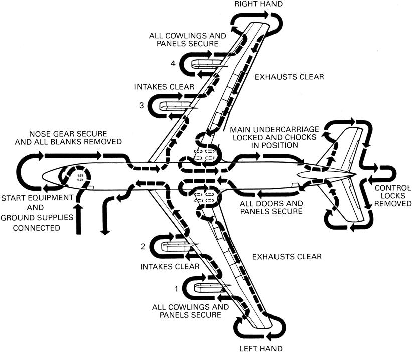
Before an engine is started, the air intake and jet pipe must be inspected to ensure that they are free from any debris or obstruction. Each operator will detail his individual pre-start inspection requirements: a typical example of this for a multi-engined aircraft is shown in Figure 12–7.
The starting drill varies between different aircraft types and a starting check procedure is normally used. Generally, all non-essential systems are switched or selected off: warning and emergency systems are checked when applicable. Finally, after ensuring that the low-pressure fuel supply is selected on, the starting cycle is initiated.
At a predetermined point during the starting cycle, the high pressure fuel shutoff valve (cock) is opened to allow fuel to pass to the fuel spray nozzles, this point varying with aircraft and engine type; on some installations the shutoff valve may be opened before the starting cycle is initiated. During the engine light-up period and subsequent acceleration to idling speed, the engine exhaust gas temperature must be carefully monitored to ensure that the maximum temperature limitation is not exceeded. If the temperature limitation appears likely to be exceeded, the shutoff valve must be closed and the starting cycle canceled; the cause and possible effect of the high temperature must then be investigated before the engine is again started.
When a turbo-propeller engine is being started, the propeller must be set to the correct starting pitch as recommended by the engine manufacturer. To provide the minimum resistance to turning and thus prevent an excessive exhaust gas temperature occurring during the starting cycle, some propellers have a special fine pitch setting.
Throttle movements should be kept to a minimum and be smooth and progressive to avoid thermal stresses associated with rapid changes in temperature. Rapid throttle movements to check the acceleration and deceleration capabilities of the engine should be made only after all other major checks have proved satisfactory and after some slower accelerations and decelerations have proved successful.
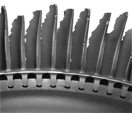
Before an engine is stopped, it should normally be allowed to run for a short period at idling speed to ensure gradual cooling of the turbine assembly. The only action required to stop the engine is the closing of the shutoff valve. The shutoff valve must not be re-opened during engine rundown, as the resulting supply of fuel can spontaneously ignite with consequent severe overheating of the turbine assembly. An example of turbine blades that have been subjected to overheating is shown in Figure 12–8.
The time taken for the engine to come to rest after the shutoff valve is closed is known as the “rundown time” and this can give an indication of any rubbing inside the engine. However, it should be borne in mind that variations in wind velocity and direction may affect the run-down time of an engine.
Maintenance Information Systems
With all gas turbine and gas turbine system applications MIS (maintenance information systems) are generally maintained by larger organizations as a way of tracking their assets and asset usage. Various information components are entered into the system, and information access and input are controlled with individual user identification numbers and passwords. Coded access limits information input to individual workers knowledge scope and specific responsibilities. Information input data may include:
• Details of specific maintenance work items, all spares, materials, and personnel hours used
• Specification of all critical machinery and spares maintained
• Changes in reorder points for spares inventory
Information gleaned from MIS systems can then be used to:
• Improve equipment selections for specific applications
• Track performance of specific maintenance practices and personnel
• Provide data and planning information for plant audits and shutdowns
• Review performance of OEM spares
• Review effectiveness of overhaul, and individual repairs by both internal personnel and external vendors
• Differentiate between effectiveness of different vendors who supply generic products or repairs
• Minimize spares inventory, by using a “JIT” (just-in-time) philosophy
• Track rental equipment costs so vendor billing can be monitored
End users have used MIS systems to justify major pressure on OEMs with respect to turbine component lives and campaign for, for instance, LCA algorithm(s) and retrofitted LCA counters to economize on their utilization of spares.
Audits of and Retrofits with GT Components and Systems4
In a perfect world, an audit would be conducted before maintenance (other than that regularly scheduled to occur), repair, and overhaul (R&O) processes to assess their need. In reality, sometimes a failure occurs first, followed by a hasty R&O to get the plant back on stream, then by an audit full of “hindsight is 20–20 vision” pronouncements and sometimes some actual preventive technology for future use. So audit in this book need not mean something that occurs “pre-need definition” or “prefailure or -efficiency drop off.” It may be well after the first horse has fled the gate. An audit could also be conducted after the introduction of new technology to assess the potential and method required to utilize that technology in a plant. The reader therefore is advised to alter any previous mental frame that thought of “audit” as implying “before (R&O)” to either “before, during, or after or some combination thereof.”
The appearance of any kind of issue or problem that requires a response on the part of an OEM, end user, or vendor of any kind generally results in an audit, under today’s conditions. The stakes are too high for this not to happen. An audit generally leads to one or more of the following for a GT, its components, or system:
• Changed scope of repair, overhaul, or regular maintenance
• Newly developed or modified repair or overhaul work scope
• Modified business aspect(s) of conducting the repair(s)
• Knowledge about a mode of failure (that may be halted with a repair or not)
• Transfer of failure or troubleshooting knowledge back into the design optimization process
• Transfer of knowledge from the audit findings into the regular maintenance schedule(s)
• Retrofit(s) to reduce overall costs per fired hour, optimize maintenance, and reduce required repair(s)
In other words, repair and overhaul is now sophisticated enough that the results of new developments in those fields are often transferred back into the OEM’s manufacturing processes or methods. OEM, independent repair shop, and end user frequently work or can work in concert, for TBO, MTBF, and operational optimization.
Most land- and marine-based gas turbine plants today, be they facilities for power generation, oil and gas production, or petrochemical or process in nature, generally are commissioned with as much haste as safety considerations will allow. Business considerations and communication problems dictate that a startup where adequate time is taken to check that startup parameters result in optimum performance of the plant is rare. Generally, the push to turn out product or power as soon as possible is the highest priority. Optimization comes later—time permitting—after the plant has been run in, when it is showing signs of wear, or when process conditions have changed enough that partial redesign or retrofit is required. Quite simply, an audit generally occurs because the owner/operator either wants to stay in business, maximize profit, or both. Or it may occur because of changing legislation or the threat of fines for pollution limits exceeded or other operational problems.
When the GE Frame 9F fleet was first commissioned around 1995, it underwent severe vibration problems. An audit that cost $1 billion and the labor of 400 engineers resulted in a “fix” that essentially meant no repair. Instead it meant improved quality control procedures during engine assembly.
Aeroengine plants are rigorously tested in a test cell and subject to shock loads, and deliberate FOD in the form of frozen chickens or worse. Most of the time, this means that when the aeroengine is hung on a wing, it performs as expected. On occasion, performance inconsistencies occur. One example of this was that, when the CFM-56 was originally hung on the Airbus A-321, fairly intense vibration was felt by passengers in certain seat rows. Some synchronous vibration had been excited. A similar vibration did not occur when the aircraft type was fitted with a different engine type, the V2500. When such issues occur, they may or may not prompt a repair (if there is deemed to be no danger, nothing may happen) that may or may not result in some form of design change.
The data collection, processing, assessment, and action plan formulation for this operational optimization process is generally called an audit. The amount of information relevant in this audit is a reflection of how well preceding design and project management activities were conducted.
An audit is basically a technical accounting process. The scope of an audit is a function of the events—design, specification, safety, operational, or maintenance in nature—that prompted it being initiated. How much ground it actually covers depends totally on the expertise of the person or persons conducting the audit.
For instance, an audit may be designated as being purely a safety audit, aimed at uncovering immediate physical hazards in a plant. However, an audit engineer who has operating expertise also may uncover items relating to performance of the machinery systems during inspection. If the audit is designated a maintenance audit, an engineer with appropriate experience might reveal areas of performance optimization. Engineers conducting a design audit of a new plant might find areas where changes would minimize required repair and overhaul.
Audits may be scheduled (for safety, design, project management, operational, maintenance, process optimization audits, and so forth) or unscheduled. The latter type occurs when precipitated by unforeseen events, such as catastrophic failures and unexpected loss or halting of production flow. When an unscheduled audit has to occur, it is appropriate that the audit person be an individual with expertise in design, specification, operations, maintenance, and performance optimization, as all these areas may need some work.
Aims of an Audit
1. Optimization of operational costs per operating hour. An audit of the operation and maintenance of an existing plant is primarily aimed at reducing ownership cost per operational hour. After the action items resulting from an audit are complete, the plant should operate on a par with the best of equivalent plants. The key to optimizing audits is to consider the rotating machinery as the heart of the entire plant system, with its associated components (piping, filters, instrumentation, and so forth) as entities that contribute to the health of the machinery and the plant as a whole.
2. Changing legislation, particularly environmental. Another major impetus for audits today is changing legislation requiring retrofits to existing plants. Changing environmental law is probably one of the major areas of changing legislation today. In certain areas, such as Southeast Asia, which is dependent on financing from the West, the real logic prompting the audit is that Western banks demand certain environmental standards for the plants in question. Getting continued financing for other plants or expansions requires the plant operators to demonstrate compliance with relevant legislation. They must show that they have undergone an independent audit that proves they have met the requirements.
3. Potential for increased thermal efficiency. Frequently, a look at changing environmental legislation also highlights the potential for increased thermal and fuel efficiency. Cogeneration (waste heat recovery) system design and installation often results. A design audit of the existing plant before commencing the project is advisable, and an operational plant audit after commissioning the system is also advisable.
Tasks
The tasks in a typical comprehensive audit of an existing plant are to:
1. Survey and correct deficiencies that curtail availability and reliability.
2. Assess current efficiency and diagnose reasons for any dropoffs in peak expected values.
3. Examine the quality control (QC) and spare parts ordering and distribution procedures for operations and maintenance, with reference to how they might improve items 1 and 2.
4. Assess condition monitoring systems and instrumentation in terms of their adequacy, potential for updating, and effectiveness.
5. Examine training and communications within the organization, as they might be improved to positively affect items 1 through 4.
6. Perform all other investigations that might result in improved performance or availability as well as reduced risk of downtime or lost efficiency.
7. Consider all the preceding with reference to the plant’s maintenance history and any known history worldwide of the machinery models in question.
8. When item 6 is complete, amend as required frequencies for maintenance inspection (such as gas turbine hot section inspections) and condition monitoring as a whole (frequency, type, and position of monitoring points).
9. Using the information from items 1 to 7, review for the long term:
Audit Planning
A thorough operations or maintenance audit of a gas turbine system includes consideration of the following items.
Phase I. Planning the Audit Administration
1. Operations management basic procedures
2. Responsibilities required of various groups
3. Operations organization and responsibility splits
4. Operations maintenance organization
5. Operations engineering organization
7. Philosophy for maximum communication and optimized interdepartmental interface
8. Maintenance auditing process
9. Specifications and basic practices
10. One time repairs and contracts
11. Cost estimates of regular/unscheduled maintenance
13. Schedule assessment of large maintenance tasks
Phase II. Activities Planned during the Audit
A Operations Activities
1. Interruptions in production, equipment failure, and contingency plans
2. Assessment of specialists and other requirements
3. Reference books and manuals
4. Internal and contractor status work reports
5. Inquiries, bids, purchase orders, requisitions, and record keeping
B Maintenance Activities
1. Feedback and communication with other departments
2. Local codes, regulations, and warranty considerations
3. Turnaround schedules, tie-ins, and segmented completion
5. Safety and emergency procedures
8. Cost control and productivity
11. Time allocation, documentation, and follow-up for changes
These are basic outlines and open to modification, adaptation, or specific omissions.
General Audit Procedures
How is this Information Gathered?
An audit primarily revolves around the following key tasks:
1. “In the field,” on-site survey of gas turbine systems. For this item, the audit person normally works against customized checklists using some or all of the material in this section.
2. Survey of operational procedures. This is conducted by completing thorough interviews with
Frequently problems arise due to miscommunication among departments, along the lines of “I know what the manual says, but the only way we can get this to work is by . . . we never got around to telling engineering” or “we found we could save time if we . . . but if we had told management, they would have . . .”
How Does this Information Provide Improvements to Maintenance and Operations?
3. Procedure items 1 and 2 are reviewed in the context of
• Would different procedures have helped?
• Would a different organizational structure help?
• Do personnel have adequate training?
• Are routine checks of trips and system safety shutdowns working?
• Are these checks done regularly and as they should be?
• Is the spare parts support system working as it should?
• Are routine maintenance supplies available when they should be?
• Are all reports complete and comprehensive?
• How does the (engine) condition monitoring system (ECMS) work, that system being real time, online; not real time, online; or intermittent (readings taken on an as-needed basis)? And, if it is one of these system types, does it need to be upgraded or downgraded?
This review is generally first conducted by the audit engineer.
4. Item 3 is repeated with all involved personnel present to provide information, feedback, suggestions, and opinions that initial interviews may not have uncovered.
How Might Standard Operating Procedures and Standard Maintenance Procedures be Altered or Affected?
5a. During procedure 4, the most advisable members to make up a team that will recommend changes to standard operating procedures (SOP) and standard maintenance procedures (SMP), usually becomes self-evident. The team, however, should represent operations (plant operator personnel), maintenance, management, and long-range planning.
5b. For a complete audit, including the internal condition of the existing machinery, the machinery must be shut down and inspected. This is advisable in cases such as:
• When taking over mature units or plants from a previous owner where proper and complete records were not maintained.
• When unsure whether the condition monitoring system on the equipment is giving as complete information as you need.
• When looking for information for specific projects, such as extending the OEM’s recommended time between overhauls or stated component lives.
Meetings have to be conducted beforehand to agree on the exact timing of these internal inspections and to arrange for the appropriate personnel, equipment, and tools to be available. Just before taking the machine out of service, a complete operational test should be made at different load settings—zero, half load, and full load are advisable.
5c. These tests should be conducted regardless of whether internal machinery inspections are included as part of the audit or not. The results of these tests should be compared to the manufacturers’ performance charts and corrected for local atmospheric conditions. Note that these tests should also be conducted before and after a major unit is overhauled. An overspeed check should be done as well, and the reaction of the governor and tripping instrumentation noted.
Together with information in the plant's maintenance information system, the results of these runs should be considered in the light of the following.
For Gas Turbines Systems, Have Any of the Following Occurred?
• Increase or change in vibration
• Compressor discharge pressure decreased
• Change in lube oil temperatures or pressures
• Air or combustion gases blowing out the shaft seal
• Incorrectly reading thermocouples
• Change in wheel space temperatures
• Fuel control valve operation
• Hydraulic control pressure changes
• Does the turbine governor “hunt”?
• Are the gear boxes emitting any sound?
• Overspeed devices, do they operate properly?
• Babbitt or other material found on lubricating oil screens
• Lube oil analysis shows corrosion increase
• Pressure drop across the heat exchangers changes
5d. Before removing turbine flange bolts or disturbing the normal turbine setting, clearance readings between the wheel shroud and the last row of turbine blades should be made at both horizontal and vertical settings. The main turbine flange should be checked for spread or warpage with feeler gauges between each of the flange bolts. Elevation checks should be compared with original readings at each of the turbine supports.
5e. Some maintain that thorough and regular borescope inspections provide enough information that machinery disassembly for an audit is not required. Ultimately, it is the machinery owner/operator’s choice. If facilities for accurate borescope information are provided and borescope checks are done by an individual qualified to interpret his observations, such checks can provide:
• Internal on-site visual checks without disassembly.
• Extending periods between scheduled internal inspections
• Accurate planning and scheduling of maintenance
• Monitoring condition of internal components
• Improved ability to predict required resources (spares, tools, personnel, expertise) for optimized operation and maintenance
5f. Some gas turbine system designs favor disassembly ease of hot section inspections better than others; that is, where duct flanges allow the hot section and downstream turbine sections to be unbolted and backed away from the rest of the turbine without restriction.
5g. First stage IGVs (inlet guide vanes) should be inspected closely for signs of operational problems. Liquid droplets in gaseous fuel is a particularly common problem, often called hot corrosion by some.
• Blade tip clearances (first and last stage of the turbine) should be checked at at least four points along the circumference, to check for blade tip rub (that may relate to excessive turbine inlet temperatures).
• Fir trees should be checked for premature cracks. Note that this is a particularly hard area to detect cracks. Discs and fir tree slots should also be checked for cracks. This also is a difficult area to detect cracks.
(Note that retrofit designs have used steam injection to add enough cooling that, for instance, discs on a GE Frame 5 were taken out of crack range. A “side” benefit of the retrofit was a substantial gain in horsepower and reduced NOx emissions.)
5i. Journal bearings may suffer from abnormal wear in the event of excessive starts. For required repairs or new repair development, such as blade tip robotic welding, specification of “new” coatings, additional heat treatment, HIPing, and so forth, or spares requirements and changes in operation limits, see the OEM manuals and reference your own and other user experience. When these two sources do not coincide, the OEM must be negotiated with until a satisfactory compromise is reached.
Changing Legislative Requirements
Let us consider emissions standards as a case in point. In many cases, proof of an independent audit often is what investors require before approving continued financing of new plants, plant expansions, and major expenditures.
Tightening SOx regulations have been responsible for “repowering” old steam turbine stations particularly (but not exclusively) in the Western hemisphere with gas turbine and combined-cycle plants. (Coal and lignite still may be used to supplement boiler heat provided by gas turbine exhaust or superheat the steam.) Inevitably, the progress of coal as a fuel affects the gas turbine business.
For instance, China’s emission standards (effective at the beginning of 1997) require sulfur oxides (SOx) emissions limits of 2100 or 1200 mg/cubic meter depending on whether the fuel has less than 1% sulfur or more. NOx emissions are stated only for units larger than 300 MW units: if liquidized slag removal is conducted in a pulverized coal boiler, 1000 mg/cubic meter is the limit; for solid slag removal, the corresponding figure is 650. For flue dust (ash or particulates), the mg/cubic meter values are 200 for urban areas, 500 for the suburbs, and 600 for old units with a residual life of more than 10 years. These are not ideal standards, but they are a help if followed. Thermal plants in China turn over 7 million tons of sulfur dioxide into the atmosphere annually, so the pressure was on investors to be seen to be supporting sound environmental policy. Most power companies in coal-rich Asia now also operate combined-cycle and gas turbine (peaking or otherwise) plants. For those that use, in part, coal or lignite fuel for their power systems, environmental legislation changes are an issue.
Korea, Southeast Asia’s most developed country after Japan, is also changing its emission standards in manageable increments. In 1995, local anthracite fueled plants had to meet 2000 mg/cubic meter for sulfur emissions, and imported coal-fueled plants had to meet 1430 mg/cubic meter. (Current NOx standard is 350 mg/cubic meter.) By 1999, however, all plants must meet 770 mg/cubic meter standards.
In Taiwan in 1992, SO2 emissions allowed were 2145 mg/cubic meter. In 1999, that was lowered to 1430 mg/cubic meter; NOx standards stayed at 720–1025 mg/cubic meter.
Lowering emissions standards with, for instance, flue gas desulfurization (FGD) techniques is an expensive and long process, with the least expensive FGD installation currently costing on the order of $85/megawatt (MW). Components external to the turbomachinery, such as installation of new furnace burners (for lowered emissions or greater fuel diversity), FGD scrubbers, precipitators, and additional stacks all potentially cause major pressure drops in the overall plant system, which should be checked in an operational audit after commissioning.
Components internal to turbomachinery sometimes are less easy to retrofit and generally come as part of a newer model, such as low nitrous oxide (low NOx) burners in a gas turbine. OEMs frequently supply retrofit kits if internal modification has been found to benefit the bulk of the fleet. If a modification is no longer prototype in status, an audit is probably not necessary. However, if it is accompanied by a change in process conditions, such as fuel heating value or moisture content, the operational balance of the system (including time between inspections or overhauls) may be changed, until investigated and corrected in an audit.
Retrofits Aimed at Operational Optimization
1. Cogeneration retrofits are frequently bulky (using waste heat off a gas turbine for greenhouse heat, adding waste heat recovery heat exchanges, and so forth). As with FGD units, major changes in system flows, back pressures, and heat balances result. An audit is advisable after the new system has been commissioned to check on the effects of the modifications.
2. One of the most common systems to be retrofit with operational optimization as a high priority, is performance analysis. The data gained from a PA system can also be used as inputs into a life cycle counter for life cycle analysis. Why do we need PA and LCA? PA help optimize fuel consumption and pick appropriate intervals to wash or clean compressors and gas turbines. LCA can be used to extend TBOs' and components' lives.
3. Addition of retrofits, such as water or steam injection to reduce NOx levels that was not part of the original design package, should also be audited to check for proper operation, after commissioning.
4. I&C (instrumentation and control) retrofit packages for increased reliability or optimized performance are perhaps the most common retrofit on existing plants.
Some I&C retrofit cases follow.
Case Study 1: Brent Platform Retrofits for Extended Life5
A monumental production expansion was undertaken at Britain’s largest oil and gas field, Brent. What had been primarily oil production was being altered to tap massive gas reserves and reduced oil supplies instead. This change required many changes in platform equipment and layout. It also gave rise to a requirement for optimization of the platforms’ control systems. The original controls on the platforms, unreliable or inaccurate by contemporary standards, would have left margin for undesirable cost increases per unit of production flow.
Summarized production changes at Brent are as follows. The 1992 and 1993 expansion initiation was aimed at extending the field life to at least 2010 (from 1998). Basically, pressure exerted on the field was dropped so hydrocarbons vaporize into gas. Oil production, which requires higher injection pressures, was reduced. Increased recovery as a result is approximately 34 million barrels of oil and 1.5 trillion cubic feet of gas.
The changes occurred in two stages. In 1997, two of Brent’s four platforms were modified, water injection stopped, and gas injection started, to begin the depressurization process. After 2000, stage 2, involving deep depressurization, begins, as water previously used for pressurization is drawn off with submersible pumps. Increased gas production and water pumping facilities are required.
Brent’s daily production consequently is expected to be about 600 million cubic feet of gas and 175,000 barrels of oil, well into this millennium. Changes to the platforms are expensive. Even with the steep learning curves cutting costs, Bravo platform cost £439 million to adapt, Charlie £363 million, with £314 million anticipated on Delta. The Achilles heel in all this ambitious planning was the control systems. The controls are also a vital part of an anticipated 15% savings in engineering and maintenance costs until possibly well into this century.
Each of Brent’s platforms once had four modules: a drill deck, production system, power system, and accommodation block. After the expansion changes, only the power system was left. Prior to expansion, the field owner, Shell, had ordered studies on reliability and new power requirements. It knew then that it had 15 years left in the field and wanted optimized, efficient running. Brent already had four Avon power plants. There were also four MW generators, two each per platform. There were Rustons on two platforms and Solar Centaurs on one platform.
In the original design, there were four Avons, since one was a backup. Part of the optimization and streamlining that optimized controls made possible was that one Avon was removed. However, now the three others had to be more reliable. Also, appropriate power management was required. One study Shell commissioned looked at the reliability of the original controls. The old control system had many relay problems, expensive in terms of their impact on production. The retrofit vendor, HSDE, supplied:
• Three governor and sequencer packages for the Avons
• One color graphics man-machine interface (MMI) for terminal-to-machine readings for the three Avons
• Two governor and sequencer packages per platform (for either the Rustons or the Solars)
• One remote color graphics MMI in the main control room
• One Brush power management system, including a fast load shedding option
Each of the five gas turbine governor and sequencer packages manages the GT system in question. It controls
on each of the 17.5 MW Avon or the Ruston or Solar 4 MW units.
The control package continuously calculates power “remaining” available. For instance, if 10 MW were generated, the system calculates how much net power is available for platform duty. This information is sent to the power management system.
Another task for this control feature is that, as per Rolls-Royce service bulletins, these Avons had to continuously run low-cycle fatigue (LCF) and thermal fatigue algorithms. Rolls Royce’s design development on the machine components meant that considerably extended component lives were possible with certain new modifications, provided extensive calculations on operational speeds and other data were performed. Anxious to preserve the life of expensive components, some operators are “hand performing” these calculations. On the Brent platforms, the LCA system does this automatically, major cost savings in time and skilled personnel.
All GT controllers are connected to Brent’s main SCADA system. Information from the potential 600 data point systems is radioed to shore, where Shell’s engineers in Aberdeen can assess their offshore operation from onshore. They also can time maintenance and parts removal with better accuracy.
The Brent platform and similar retrofits frequently use the stepper motor valve and MMIs.
Stepper Motor Valve
The stepper valve is a fast response electrically operated valve (pioneered by HSDE). It is generally used in fuel systems. It provides the fast response required by aeroderivative and some industrial gas turbines. Before the stepper valve made its appearance, some users tried to use hydraulic and pneumatic actuation to provide the required response time, but this increased the overall complexity of the fuel system. As always with instances where system complexity is escalated, system cost rose while mean time between failures and availability decreased.
The design fulfills the original design aims, which included the following safety considerations:
• The liquid fuel version of the valve incorporates a pressure relief valve, protecting the system against overpressure and the fuel pump running on empty or “dead heading,” caused by closure of valves downstream of the fuel valve during system operation.
• A fail freeze or fail closed option, depending on whether the operator is a pipeline (in which case, turbine shutdown on valve failure is required) or a power generation facility (“freezing” at the last power setting is then required).
• High-speed response of less than 60 mS required by aeroderivative gas turbines to prevent overspeed in block offload conditions.
• 24 volts DC is the maximum drive voltage that ensures personnel safety.
• Explosion-proof actuation to BASEEFA/CENELEC 50014 and 50018 category EEx d IIB T4 90°C ambient and CSA Class 1, Group D, Divisions 1 and 2, which allows operation in hazardous methane service.
• Resistance to fuel contaminants including tar, shale, water, and sand.
• Corrosion resistance in components exposed to wet fuel, and corrosion resistance to all parts if the service is sour gas.
Other operational objectives that shaped the design were an operator’s requirements for:
• Higher mean time between failures (MTBF). A target of 50,000 hours was set and achieved.
• Low mean time to repair (LMTR). The target of 1 hour, achieved with modular design, together with the target MTBF provided an availability of 99.998%.
• Low maintenance costs, since the modular design can be repaired by an individual with relatively low expertise. Service intervals are 12 months.
• Low power consumption, since an electric motor of less than 100 W is used. This eliminates the need for additional hydraulic or pneumatic systems. Also black starting is more reliable if the fuel system is powered by the same batteries as the controller.
• Large control ratio, which allows control over the ignition to full load as well as full speed ranges to be possible with one fuel valve. Fuel pressure variation compensation is provided. The additional speed ratio type control valve found in many other industrial gas fueled installations is not required here.
MMIs
A man-machine interface (MMI) is the display unit interface with the I, C&D OEMs PLC (for example, HSDE’s Digitrend unit). About 500 to 600 readings are fed into the PLC, which provides:
• Functional mimic diagrams for monitoring and control of the turbine/generator set for power generation or the turbine/driven equipment system for mechanical drive applications
As with the packages of many OEMs that build C, I&D packages, this system was built to rival the OEM’s equivalent units, such as the GE Speedtronic Mark V system. It thus can displace GE packages for LM 1600, LM 2500, GE Frame 3s, and GE Frame 5s. End user requirements include:
• Better reliability than with analog systems that may experience frequent outages
• Better availability with digital feedback start control and consistently repeatable starting under all ambient conditions
• Improved performance minus the drift seen with alteration of ambient conditions in some older systems
• Optimized maintenance, since the digital controller does not require regular maintenance or calibration Cooler starting, steadier operation, and more precise temperature control (than possible with analog systems) reduces required engine maintenance
• A modular design concept that means that the controller’s processing requirements are dealt with on a platform dedicated to the performance and response requirements of the particular engine being controlled
• Integration with digital SCADA system data storage is possible with standard serial communication links and protocols
• Improved life cycle costs result, as is generally the case with digital versus analog controlled engine system
• Reduced operational risk is achieved particularly during commissioning, as digital controls provide a greater degree of influence over process fluctuations and surges that are common during startup
C, I&D vendors seek compatibility for their products with as many GT OEMs “original” systems as possible.
Case Study 2: Flotta Terminal6
The Flotta terminal is just off the Scottish coast on the Orkney Isles. It acts as a collection and shipping center for oil produced at the Claymore, Scapa, Highlander, Ivanhoe/Rob Roy, and Tartan rigs. Elf Enterprise Caledonia, the terminal operator, decided on a retrofit that would:
• Reduce its required personnel level on the platform
• Revamp existing instrumentation to improve operational maintainability, availability, and running costs
The terminal’s power is generated by six Ruston TD4000 gas turbines that drive Brush alternators. The number of units run at any time varies. Three or four normally are run, but all six may be required if the terminal is exporting. The C, I&D vendor’s controls solution included:
• Replacing existing turbine controls with digital (HSDE Digicon) controllers. Communication multiplexers assist this within existing unit control panels, therefore requiring a minimum of disturbance to the station’s equipment.
• Fitting a new power management system that incorporates individual autosynchronizers instead of the previous shared unit. The new control system uses fiber optic links to incorporate gas turbine and electrical generation integration control among the six gas turbines.
• Existing pneumatic fuel valves (the turbines run on gas or liquid fuel) were replaced with electrically actuated valves. The improved response time reduces wear on turbine components, which could result from liquid fuel “slugging” in what is supposed to be gaseous fuel.
• Gas fuel pressure regulators with fixed settings were fitted.
• New visual display unit (VDU) workstations and interfaces in the Oil Movements Control Room (OMCR) and Power House Control Room (PHCR).
The VDUs made it possible to reduce PHCR personnel (only three to zero personnel are required now) and control it from the OMCR. They also provide far better graphics than the previous dot matrix printout and provide 20% more readings. The VDUs online information is digital, so accuracy is improved. The computers that run the VDUs can recall about 3 months worth of data, as well as recall archival data for condition monitoring and troubleshooting.
The VDUs are easy for operators to read and very user friendly. Other useful data items the VDU terminals present include:
• Power factor values, which make power control easier.
• An EGT spread diagram, which makes gas turbine “hot spots” or combustor problems graphically evident. (The system allows for one thermocouple out of two in each quadrant to fail and still provide a reading. The failed probes are removed from the average EGT calculation and nuisance trips thus are avoided.)
• Digital readings for fuel lower heating value (LHV) and volume flow rates (not part of the fiscal accounting system) are available for machinery performance monitoring.
The new control system allows for generators 4, 5, and 6 to be connected, via the export board, to the Scottish Hydro Electric PLC distribution network (for sale of any excess power the station produces) or to the station’s terminal board. When power is exported, the control system provides equal power sharing between generators at a given base load. (Generators 1, 2, and 3 may be connected to the terminal board only.) Thus power is efficiently and economically distributed at all times.
Case Study 3: Forties Platform Retrofits7
Original oil production estimates at Forties were once 1.8 billion barrels recoverable over 17 years. New technology and exploration methods increased that estimate, in 1996, to 2.48 billion barrels recoverable (from 4.2 billion in situ) over a life of 30 years or more. At the end of 1996, 180 million recoverable barrels were thought to be left. That is, until Forties’ partners revealed that they might be able to extract a further 400 million barrels and run till 2011. Key to achievement of these goals was an optimized control system.
The original controls were no longer state of the art by any means. The 20-year-old system was an analog one with potentiometers. Problems associated with a system of this vintage were typical. They included:
• Sporadic reliability. Unscheduled shutdowns numbered 32 a month on average.
• Start availability could not be relied on.
• System response time left a great deal to be desired.
• An antiquated surge control system took its cue from a straight line (instead of a curve) that operated 15–20% from the surge line, causing major efficiency penalties.
• During annual startup procedures, the gas turbines would keep tripping when they were switched to gas fuel after being started on diesel.
• This would also result in 2–3 days' lost production time when a fuel change over was required.
• “Overfuel” also frequently resulted when fuel was changed over. This was costly in terms of turbine hot section component lives.
• Many spares required for the original system are now obsolete.
• The diesel fuel bill was unnecessarily large due to inadequate controls’ response times.
For updating the Forties NGL compressor control systems, an I&C vendor supplied the following control equipment:
• A control system (HSDE Digicon Series 2 Ace), which governs and sequences the gas turbine, NGL compressor, and associated systems. The controller also includes fault and failure monitoring for the entire turbomachinery train, including turbine, compressor, and pump units.
• NGL compressor antisurge system.
• NGL compressor load share system.
The fuel control system now continues to support gas, diesel, or combined fuel usage, only now it is far more reliable. Consumption of costly diesel fuel is minimized.
Case Study 4: Al-Ain Flameout Problems8
Al-Ain, a power station in Abu Dhabi, has Westinghouse W251 generators that run Brush alternators. A C, I&D vendor was awarded the contract to replace the existing control panels for the generators. The original governor control system had been pneumatic. This system had experienced constant problems with sticking pneumatic valves during startup. This, in turn, caused flameout problems with the gas turbines. The system was both temperamental and unreliable. Only one operator understood how to fix the problem, so the station could have found itself at a standstill in this man’s absence. This was an intolerable situation from the operator’s standpoint.
The station ordered replacement control panels from an I&C vendor, the main features of which are:
• A control system (Digicon Series II Ace Control System, which incorporates the Digicon Overspeed Trip Unit, Input/Output Expander units, which extend potential input) and a fuel valve actuator drive unit. This unit is motor driven, which removes the unreliability problem experienced with pneumatics.
• An MMI system with a capacity for 200 inlet data points.
• 16-way annunciator with indicator lights.
• Modified pressure gauge panel adapted for reduced pneumatic control.
Modifications made to the gas turbine instrumentation include replacement of pneumatically controlled gas and liquid valves with actuator-driven throttle valves. The gas turbines are controlled and monitored by the I&C vendor’s (Digicon Ace) units. The controls permit independent operation of both turbines, so one can run without the other being affected in any way—a vital feature to most operators of similar stations.
Each turbine control panel also has an ABB Synchrotact 4 dual channel unit. This unit safeguards the generator synchronization, includes the vibration monitors, and has an overspeed trip detector (Digicon OTU).
Via a dual communications link, the Digicon Ace controls the interface with the MMIs in the turbine control panels. They in turn provide dual communications to the two MMIs in the control room. The MMIs provide the operators with mimics that reveal present problems or operational trends.
Performance Analysis9
What is performance analysis/monitoring? Basically it is a check of the fluid path of an item of turbomachinery (gas turbine, compressor, and so forth) to determine that it is doing what it was designed and bought to do. To perform this check, the pressures, temperatures, and flow along the machinery’s gas path may be used to compare its performance curves of:
and so forth. The readings may then be computed for the operator to either deduce what corrective action is required or read off the required action on an automated system display.
Performance analysis systems occur in three main “formats”:
1. Systems that have a calculation module based on actual instrumentation readings. Such systems may cost about $15,000 and up for the first unit, with discounts for additional units of the same model.
2. Systems that have a calculation module based on actual instrumentation readings, as well as a calculation module that uses predictive flow formulae theory and compares the two for better quality information and indication of which instrument may be malfunctioning. Such systems may cost from about $60,000, for the first unit with discounts for additional units of the same model.
3. Systems that perform the functions of 2 (above) and are part of an overall online (frequently real time as well) health monitoring system that incorporates vibration monitoring and other monitoring. Such a system uses artificial intelligence techniques to attempt automated problem solving. Such a system is generally extremely expensive. Typically, these systems cost from about $100,000 per machine train (no discounts for similar trains sometimes) to $250,000 per train.
They may frequently also be “overkill” for an application. Typically they take about 600 readings/signals as inputs to arrive at their conclusions. Frequently, their specifications also demand a requirement that “eliminates” the competition. Their manufacturers may claim its system's use absolves the operator of using his or her own system knowledge or reasoning by providing “ready” answers. Sometimes this works for certain problems, if those were programmed into the artificial intelligence logic. The customer may get the best value for money from comprehensive vibration analysis and a system that incorporates the capabilities of the system in category 2.
In this section, we discuss a system in generic category 2. This generally provides the best economic return in terms of ($ saved/$ capital cost) for a PA system and, therefore, is one of the most important items in this chapter.
• Summarization of the cost, operational benefits, and return on investment of a PA system
• How such a system works, to compare it against other options and ask manufacturers the right questions
1. Check detailed performance for different modules
2. Predict performance through the load range
3. Check machine in normal operation, not just when it has just been cleaned or newly overhauled
4. Check performance of CC or other complex cycles
5. Self-check and help troubleshoot
6. System must be interactive and simple to run
7. Check costs for different configurations
8. Check costs differential for different operational conditions
When successful, a PA system enhances:
While setting up reference data the following parameters were varied:
3. Axial compressor flow degradation
4. Axial compressor efficiency degradation
The diagnostic module input data included:
2. Ambient dry bulb temperature
3. Ambient wet bulb temperature
5. Compressor delivery pressure
Any measurement errors are usually with 4, 5, 7, and 8.
Gas path analysis steps (from preceding instrument data):
1. Calculate compressor inlet flow
2. Calculate TIT from turbine swallowing capacity
3. Calculate turbine efficiency degradation
4. Calculate compressor efficiency
5. Calculate “clean” compressor flow and efficiency, then calculate flow and efficiency degradation
Experience indicates that the following ranges usually apply:
• For compressor flow degradation: 0–8%
• For compressor efficiency degradation 0–6%
In the predictive module, predictive values are calculated (fuel flows are interpolated). Fuel consumption is calculated for all combinations of:
A second set is required if you have an anti-icing system.
Predictive programs are useful for CC, cogeneration, and complex cycles. This set of “grid” values can be included in automatic, online, and real-time systems. A practical use of modeling is in the sale of product (gas, power) versus fuel consumption.
An end user is advised to look for the following features in a PA system:
• Analysis is aerodynamic, not just a heat balance with the machine represented by a black box.
• Predicts stage efficiency, pressure ratio, exit angle, gas properties, and swallowing capacity.
• Subroutine handles the following losses—profile, incidence, trailing edge thickness, tip clearance, shock, end wall, and secondary.
• Cooling air, flame flare, and similar flow interruptions are treated as blockages to help accurate modeling.
The advantages and uses of such a system include:
• Application in sales based on fuel consumption measured more accurately than with normal fuel flow meters.
• Ability to set up the system to determine the optimum combination in a machinery train for a certain load level.
• Cooling flow modifications can be analyzed to prevent problems such as disc cracking.
• Similarly, blade cooling modifications can be made.
• Analyzing steam and water injection effects (reduced maintenance, power increases, NOx reduction).
• Analysis of gasifiers (GT operated to drive the compressor only) to supply pressurized gas. Being able to analyze each stage helped this development of modified running of a gas turbine (consider applications that require large quantities of pressurized gas).
Note that it should be simple to correct for data inputs that can cause errors due to factors such as:
1. Compressor delivery temperature being affected by heat transfer in the combustor; solution, calibrate each engine.
2. Inlet and exhaust pressure loss errors; solution, measure periodically.
3. Fuel composition; solution, get accurate samples.
4. Modifications (e.g., IGVs) are added; solution, model into solution.
5. Atmospheric condition errors; solution, do not forget barometer and rat. humidity readings daily (if not incorporated in real time into program).
Case Study 5: Extending TBOs of Gas Turbines by Preventing Premature Turbine Disc Failure in a GE Frame 5 (Old Model)10
Consider that turbine disc lives in some industrial gas turbines are limited to less than 100,000 hours. This is due to high temperature creep cracks formed when the engine is operated at full load, which, in turn, causes costly repairs and disastrous failures. This can be avoided and disc lives extended to over 100,000 hours by using performance monitoring software to analyze changes to the disc cooling. Note that, before this was done, changing the disc material was tried, but this did not work. The cracks persisted.
The cracks were at the bottom of the fir tree and difficult to see. The investigators noted that the cracks occurred in the blade root slots of the disc. Typically cracks would start along grain boundaries.
In gas path terms, at each disc root compressor air and hot gas path air accumulates. In other words, hot air accumulates where it should not. The solution in this case was to feed cool air through diaphragms. No rotating components were affected, just the diaphragms. Rows 3 and 4 had compressor delivery (discharge) air, row 5 had intermediate stage compressor air from the bleed valve (see Table 12–2). The net effect on performance was negligible:
TABLE 12–2
Comparison of Measured and Predicted Values of Engine Parameters [12-4]
| Predicted | Actual | |
| Increased combustion temperature | 6.7–7.2 | 6.7 |
| Increased exhaust temperature | 2.2–3.9 | 1.1 |
| Decreased compressor delivery pressure | 0.9 psi | 0.7 psi |
| 6.2 kPa | 4.8 kPa | |
| Increased Fuel Flow | ||
| (lb/s) | 0.011–0.019 | 0.016 |
| (kg/s) | 0.005–0.009 | 0.007 |
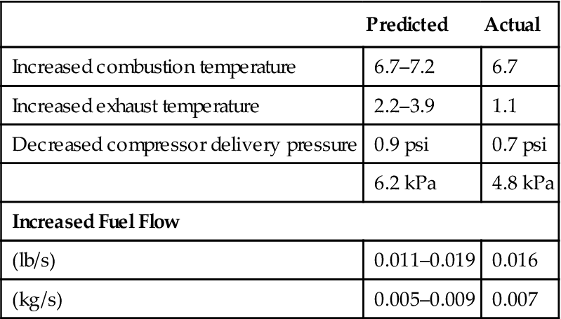
Case Study 6: Power Addition for GT in Cogeneration Service Using Steam Injection10
Operation of this system works best when:
• Steam is injected only when a certain power is reached
• Best efficiency is to inject all excess steam and let control system vary IGVs and fuel flow
• Keep steam lines hot with a small amount of condensate even when steam is not running
Summary: 30% more power is possible when injecting steam equivalent to 7.5% of compressor inlet flow. Note: NOx levels were down from 83 ppm to 12 ppm.
Integration of Detection, Assessment, and Planning in Audits11
If qualified people are conducting the audit, the detection (of faults and potential improvements), assessment (of how much of a fault or potential benefit is possible), and planning (how to implement the steps necessary) are a set of steps that blend seamlessly with each other. To be alerted to potential problems, most operators (land, sea, and air) depend on vibration analysis to be a first line of defense.
Vibration Used to Assess Gas Turbine Combustor Problems
With the development of more accurate vibration probes, it has been possible to pick up the signal noise that occurs with deterioration, such as cracks, of gas turbine combustion cans and liners. Ideally, the health of these gas path items is monitored continually, and there will be indications via vibration monitors of impending work in this area.
The inspections, work, and additional sparing can be done as part of the preparation for the actual audit.
This illustrates, as on previous occasions, that the shape nonroutine audit work takes follow, at least in part, the results of previous troubleshooting efforts. If vibration analysis does not pick up combustion section problems (they have been known to pick them up before exhaust gas temperature, EGT, monitoring with thermocouples), then EGT monitoring or regular borescope inspections should detect this condition before disastrous failure occurs.
Optimizing Vibration Analysis to Extend Its Problem Detection Capability
For the most part, mature plants have displacement, velocity probes, or both. These cannot detect high-frequency problems well. All three kinds of probes should be used for maximum effectiveness.
Look for red herrings. With vibration analysis, these frequently come from outside the machine, even if their effects are read on the machine.
Sources of vibration from outside the machine include:
1. Piping stresses—static, cantilevered
2. Foundation problems, including
• Frost melting or permafrost problems
• Moving soil (muskeg or other shifting soil insufficiently removed)
• Foundation inclusions (grout problems, soft feet, and so forth)
3. Extreme climatic change causing additional stresses in piping and so forth
Anticipating Repairs Needed Based on Gas Path Analysis
When the results of vibration, EGT, and borescope monitoring are fed back into audit information collecting, the audit team may decide to:
1. Alter periodicity of hot section inspections,
2. Run certain components on condition,
3. Run the gas turbine derated,
5. Buy or stock updated hot section component parts,
6. Ask OEMs for life cycle algorithms,
7. Install life cycle counters, or any other relevant work items or any combination thereof.
With respect to the fuel system, they may decide they need to:
8. Change the fuel nozzle design,
9. Change the fuel nozzles more often,
10. Install a fuel treatment system,
11. Check on the working of the fuel treatment system,
12. Change the wash cycle frequency,
13. Change the wash cycle fluid/cleaner,
14. Accurately monitor and analyze gas path performance for system optimization (this may have to be retrofitted),
15. Install additional filters, preheaters, or other components in the fuel system,
17. Install additional cooling air flow into the hot section,
or any relevant combination thereof.
Assessing TBO and Maintenance Changes Made Necessary by Changing Fuel or Fuel Composition
Fuel selection and systems can be the biggest cause of adverse effects on TBO and maintenance schedules (see Chapter 7, Gas Turbine Fuel Systems and Fuels).
As noted in Chapter 7, there are differences in composition with common liquid fuels. A change in fuel type may require extensive changes in associated fuel systems. Maintenance intervals for gas turbines can be influenced by fuel type. Fuel selection can have a drastic effect on TBOs and maintenance intervals. Heavier fuels cause higher TITs and consequently reduce turbine component life still further.
More and more, turbine combustion systems are being designed to burn gaseous, liquid, or two-phase fuels. Audit of a mature facility may reveal a need for a change in fuel type, in the event of
1. Availability issues arising from, for instance,
a. Decrease in production gas flow,
b. An economic moratorium on gas,
c. Disruptions in gas flow (for example, storms at sea in Thailand interrupt production gas flow and necessitate use of diesel fuel for prolonged periods of time).
2. Molecular weight changes, common with mixed fields, which almost always result in a change in heating value of the gas. Liquid fuels do not exhibit as much variation in heating value as gaseous fuels. Heating values of gas may vary for between 1050 BTU/cubic foot, to 300 BTU/cubic foot for process gas. This is a differential of over 300%, which means that the fuel system required to handle either extreme for the same turbine would be vastly different.
3. Cleanliness issues, nearly always accompany changing field composition conditions. Frequently gas quantities decline, and oil and water carryover in gas flows start. Water leads to oxidation in the fuel system and poor combustion.
4. This carryover, in turn, can promote corrosion, hot corrosion, and fuel nozzle spray problems as liquid carryover flashes on contact with first-stage IGVs. Solid particulates and metallic particulates that are not strained out of the fuel supply can also be contaminants. They can plug fuel nozzles. Fuel treatment systems can be used to remove harmful metal contaminants such as vanadium.
5. Deposition and fouling may occur in compression trains that handle the gaseous product.
Any audit should include a comprehensive battery of tests for the fuel being used, in addition to molecular weight:
1. Carbon residue is found by burning a sample of fuel and weighing the carbon left. This property provides an indication of a fuel’s tendency to deposit carbon on the fuel nozzles and combustion liner. The value should be compared with the one from the last audit or plant startup or last significant operational date.
2. Viscosity affects the pressure loss in pipe flow.
3. Pour point is the lowest temperature at which fuel can be poured under gravitational influence. Items 2 and 3 affect a fuel’s tendency to foul a fuel system and determine to what extent preheating of the fuel system is a requirement.
4. Ash content of liquid fuels helps determine the cleanliness, deposition, and corrosion characteristics of a fuel. Ash is present as either oil- or water-soluble traces of metals or solid particles (sediment). High ash fuels are highly corrosive.
5. Contaminants in the gaseous fuel that may have increased since the last analysis include tar, coke, sand, lamp black, and lube oil.
Consider a typical gaseous fuel specification (see Chapter 7, Gas Turbine Fuel Systems and Fuels). Commonly, the maximum variation tolerated on a given gas turbine fuel system of these properties is ±10%. As design development of gas turbines continues, and partly towards contribution of OEMs environmental effort, fuel systems that handle gas of heating values of less than 100 BTU/cubic foot are being developed.
With a typical liquid fuel specification, the limits set for viscosity, water, and sediment percentages by volume are required to prevent clogging of the fuel system.
If pour point criteria are not met, fuel preheating is required. The hydrogen minimum limits fuel smoking. The sulfur maximum limits corrosion due to sulfur.
Vanadium, sodium, potassium, and lead form compounds that cause corrosion at elevated temperatures. They, as well as compounds formed with calcium, can cause deposits on blades. Alkaline sulfates of sodium and potassium, as well as liquid vanadium, contribute to hot corrosion, particularly on the first stage IGVs, as they reduce the layer of protective oxide on the metal.
The test to determine carbon content of a fuel depends on whether the fuel is light or heavy. With a heavy fuel, carbon content in 100% of the sample is determined. For a light fuel, about 90% of the sample is vaporized and the carbon content is found in the remaining amount. This test is to determine the fuel’s tendency to form deposits in the combustion system.
Ash is the material left after fuel combustion has occurred. The ash contains solid particles from fuel combustion and oil- or water-soluble metallic compounds. These metallic compounds cause the fuel to be corrosive.
Changes in the fuel’s viscosity may require some pumping system changes.
The specific gravity of a fuel determines parameters on a centrifugal fuel washing system.
A luminosity test measures the amount of thermal radiation potential (chemical energy content) of a fuel.
Volatility determines how heavy a fuel is. A residual fuel is fuel that is left after a distillation process is complete.
Sulfur content determines sulfidation potential. Increase in sulfur content of gases can promote hot corrosion of the first stage nozzle guide vanes.
Consider the following reactions:
• In nickel-based alloys, protective oxide films are formed as follows:
• The nickel alloy is exposed to oxidizing gas, so a protective layer of oxide forms as per these reactions.
• Alkaline sulfates are formed as follows:
• The source of the sodium is salt (NaCl). Sulfur comes from the fuel.
Metal ions in the protective oxidizing film combine with molten alkaline sodium sulfate, which destroys the protective layer. Sulfidation products include nickel sulfide and chromium trisulfide. Chloride ions from the salt (NaCl) cause intergranular corrosion as they collect at the grain boundaries. As these reactions occur, the oxide film becomes porous and deterioration occurs at an increasingly fast rate.
Other oxides can be formed, as per these examples:
Catastrophic oxidation requires the presence of sodium sulfate and elements such as vanadium or molybdenum.
Crude oils are high in vanadium. Their ash contains 65% or higher vanadium pentoxide.
Corrosion is accelerated with temperature rise. At temperatures over 815°C, sulfidation takes place rapidly. Hence, the low temperature philosophy used by some gas turbine models (such as ABB’s 11N2) versus their equivalent horsepower “sister models” that attain higher efficiencies but use higher TITs. At lower temperatures, vanadium pentoxide can catalyze oxidation to attain damage rates that exceed those caused by sulfidation. Hence, the fuel treatment system that is required for all designs that burn low-grade fuels.
Typical fuel treatment systems are covered in some detail in Chapter 7, Gas Turbine Fuel Systems and Fuels.
Financial Factors with Respect to Fuel
An operator should burn the most economical fuel in terms of what fuel choice does to the cost per fired hour versus the cheapest fuel. This choice may change in the life of a gas turbine. In the case of users with a “natural” supply of clean, dry, sweet natural gas, this is likely to be their optimum fuel, for the time being. “For the time being,” as the price of natural gas is being kept artificially low by most of the countries where it occurs naturally, including Malaysia and North Sea producers such as England. However, the current moratorium on gas in England indicates that this may not always be the case. Part of the logic for this is the high premium natural-gas-poor countries, such as Japan and Thailand, will pay for natural gas or LNG.
If natural gas tariffs were raised to realistic values versus other fuels available, other fuels could better “compete” with natural gas even in gas-rich countries. In terms of environmentally responsible fuels, on the other hand, natural gas produces only half the carbon dioxide of oil and an even smaller fraction than produced by coal combustion. Solidification of carbon dioxide after combustion is about 20 years away from being commercialized.
All this notwithstanding, the demand for viable alternative, if not regenerable, fuels that, for instance, may be gaseous or liquid by-products of a chemical process, is increasing. Currently, users conduct what fuel treatment (changes) may be required, use technology to remove NOx and SOx, and tolerate the carbon dioxide emissions (or plant trees).
See also Chapter 7, Gas Turbine Fuel Systems and Fuels.
Assessing Changes Required for Turbine Cleaning Procedures
Fuel treatment and washing, if done properly, remove corrosion risk even with poor-quality fuel, such as residual fuel. However, the fuel ash and magnesium compounds deposit on turbine airfoil surfaces. For intermittent operation of 100 hours or less, the deposit does not build up, as it falls off each time the turbine is fired. If the turbine is in continuous operation, however, the first stage nozzles eventually plug at the rate of between 5 and 12% per 100 hours.
For any application where residue is built up and to extend time between shutdown intervals, mild abrasive cleaners may be used. Examples of such cleaners are walnut shells, rice, and spent catalyst. Generally, dry cleaning is initiated after a 5–10% power dropoff; typically, this removes 50% of the deposits. To get better cleaning (100% power recovery), water or liquid cleaning becomes necessary.
See also Chapter 8, Accessory Systems.
Hot Section Maintenance Assessment
Combustion chambers can be inspected directly in a hot section inspection. Borescope checks may also reveal cracks or burned areas. Many small cracks are common. The key is, Are the cracks such that they might join together and cause a loss of a part of the combustor metal? Depending on length and OEM manual limits, cracks of this kind often can be weld repaired. Burned or warped areas can be cut out and replacement metal welded in place. Extensions to OEM allowed tolerances need to be made with appropriate care and experience.
The location of all combustion chamber damage should be considered with respect to:
1. Irregularities in flame patterns
2. Blockages in air or fuel flow
3. Cross tube damage or incipient failure
4. Erosion of or dirt in fuel nozzles
5. “Hot spots” that require investigation as to the root cause, such as excessive flow
Combustion chamber position should be located with a reference point; that is, an annular combustor should be put back in the same position between physical inspections. With can annular combustors, each can’s location in the turbine should be referenced, each can have its own permanent number. Complete records should be maintained on all combustion sections, including repair scope and dates. The can location hardware should be checked for signs of vibration or thermal movement.
Plan Maintenance, Engineering Changes, and Retrofits Based on Operational Detection and Assessment
Obviously, there are close links between audits, troubleshooting, and life cycle assessment. Data sheet formats, as well as typical system arrangements for turbomachinery types for most API specifications need to be collected. These give the operator a list of many obvious items to check that frequently are so obvious that they are missed.
External Factors and Operations Considerations
Ground-based operators would pay particular (but not limit their) attention to:
1. Environmental emissions regulations and changes in this area that might offer opportunities for optimized operations and maintenance. For instance, Alstom GTs that uses a silo combustor design for many of its gas turbines may require water injection because only one burner has a tendency to promote NOx formation. Now, Alstom offers a retrofit of a series of EV burners on its GT-10s and -8s instead of the single burner plus the water injection. For operators that have clean natural gas or good quality diesel, this is helpful, as water injection requires boiler feedwater quality. The operator would get no additional horsepower “caused” by the water injection, however.
2. Problem generators that have any history of coil burnout.
3. Changing fuel availability (like EGAT, Thailand, whose offshore gas supply frequently is cut off by storms at sea) or government fuel policy (for instance, the United Kingdom’s current moratorium on gas).
5. Cooling water discharge temperature and pollutant content.
With aeroengines, emissions is the main environmental concern.
However, by far the greatest concern to any operator is minimizing cost per operational hour. Cost of maintenance can make up a sizeable portion of that, and within that portion, the cost of spare parts is frequently a major issue with operators.
All audits should aim at moving in the direction of “on condition” operation, whether operators are upstream oil and gas, power generation, petrochemical, or anything else.
Assess Parts Pools Requirements
Smaller operators frequently resort to a communal “parts pool” to avoid warehousing and holding inventory. This has both obvious advantages and disadvantages.
Larger operators adapt their spares philosophy to match the OEM with which they have to deal. For instance, Solar gives its customers a spare engine while their own is overhauled, so these customers do not keep any spares.
Decide on Repair Development: OEMs or Independents
OEMs are reluctant to develop more repairs than necessary. It means they cannot sell as many spare parts. So, for instance, for the project involving cracked GE Frame 5 discs that we looked at previously, the operator had to get an independent to work on it. Note that this may end up being a “one-off” project, as prematurely cracking discs or other components failing prematurely may occur as a consequence of changes in individual operator's process or inconsistency in the OEMs manufacturing QC. (Another example of inconsistency was the GE 9F rotor vibration problem in 1995 and 1996. Not all the engines delivered had the same extent of disassembly and other problems.)
Generally, when an impatient operator goes to an independent metallurgical shop and gets a repair process that works, the OEMs feel pressured into developing their own or getting a subcontractor to do that process for them. Or even if they have their own process, they may subcontract “overflow.”
Powder metallurgy is a good example. Both GE and Westinghouse give repair work to independent vendors. Some major OEMs can also buy the powder metallurgy technology license and equipment from the independent repair shop that developed the technology. Blade tip robotic welding is another. Pratt and Whitney bought the entire rig and technology license from a vendor that developed it for their Singapore repair shop.
There is not enough time to cover all the modern useful repair techniques on the market, which enhance life cycle usage. We will briefly cover some that have the most money and problem saving potential below.
Also, at the end of this chapter, Case 9 describes the painstaking development of repairs for -F technology by an independent facility. This gives the reader a good appreciation of the investment and lead time required to develop reliable repairs.
Powder Metallurgy12
The “powder” is a plasticine type material used to fill in damaged portions or contours on blades and vanes to have the powder blend with the original material. This method retains most of the strength of the original airfoil and has far better properties than lower strength weld fillers. This repair is suitable for high-strength nickel and cobalt superalloys, such as IN738 and Rene 80. Because it is a nonfusion method, it is useful for crack-sensitive alloys that cannot be weld repaired. The powder mix can be engineered for better strength, oxidation, or wear resistance. The repair is suitable for:
• Wide gap repairs that follow the routing of material cracks of defects
• Repair of structural areas in blades, vanes, and cases
• Dimensional buildup of worn parts
• Repair of complex geometries that are difficult to weld
• Manufacture of blade tips with better oxidation and erosion resistance
Powder metallurgy technology also, in the case of a few vendors, can be purchased under a license agreement. Costs for equipment and the license range from about $500,000 upward.
Many OEMs have not opted to own their own technology for this process. Some have a few subsuppliers to which they contract this work. This, therefore, can be a high lead time item under these circumstances. In some cases, an OEM gives a kind of blanket approval to an independent facility, which has done a great deal of work for it and whose metallurgical integrity it has checked. This would generally need to be done by destructive testing, such as sectioning or X-ray diffraction. Once a facility has that kind of approval, it can solicit business directly from end users, particularly those whose equipment is no longer under warranty.
If the independent facility is large enough, then the OEM sometimes has its own representatives resident at that facility to approve “one-off” or “general rule” repairs for specific components, which are then generally the intellectual property of that facility.
This is an involved and complex technology as Case 10 at the end of this chapter indicates.
Blade Tip Robotic Welding13
This technology is getting better accepted all the time, its main restriction being the cost of the repair equipment, about $500,000 and up for first-time overhead costs.
The actual welding that occurs with this system is not new in itself. The advantage is that robotics provides a steady “feed” rate, which then eliminates the warpage that results from human handwork, however skilled. This then also means that the depth down the airfoil height that can be repaired is also increased, thereby extending the life of rotating components, which might have worn tips but not used up their useful metallurgical life.
This system also can be used to follow the geometry and repair of shrouds, high-pressure blade tips and shrouds, air seals, and compressor blade tips.
CNC TIG Welding
These systems use computer numerical control similar to the previous system’s. Again, their advantage is that uniform feed rates eliminate warpage caused by uneven heat rates. Typically, this repair can be used to repair slots on fan cases, slots on fan blades, worn segments on turbine module cases, and casings and so forth. The rig is programmed differently for each component.
Plasma Robots
Plasma layers have been used for years by manual sprayers to build up module casing flanges and lips, so everything will fit within tolerances again. Robots remove the old disadvantage, which was that, when the layers were not put on uniformly, the plasma often tended to flake, causing expensive “recycling” in the overhaul procedure, which the novice customer might end up paying for, if it had not learned to question the item.
CNC Measuring Machines
These machines, capable of five-decimal place accuracy, are programmed for every component they measure. They are used for critical bearing and seal components and checking overhauled cases and sub-assemblies. The working limitation on these is table size. The machine with a table that will fit bearing and seal components generally is about 60% of the cost of the unit that handles midsize cases of, say, 20,000 HP machines. To handle larger engine components, a larger machine has to be bought. These machines have to be housed in climatically controlled rooms.
Coatings for Erosion and Corrosion Resistance
This is one of the fastest moving fields in repair technology, and many coating manufacturers and metallurgical facilities continue to develop new coatings with higher upper performance ceilings as measured by corrosion, oxidation (high temperatures), or erosion resistance.
One erosion-resistant coating is reactive ion coating (RIC). RIC is a plasma-assisted electron beam deposition process used to deposit wear-resistant titanium nitride coatings. Some processes (different facilities develop their own) use a deposition temperature of 450°C on a variety of component thicknesses.
Another erosion-resistant coating type is low-temperature chemical vapor deposition, which applies titanium nitride at 550–625°C.
These low-temperature applications avoid the problem associated with distortion and tempering of tool type steels by application temperatures (1000°C) in conventional chemical vapor deposition.
Several processes can be used to apply aluminide coatings to hot section components. A preferred method uses chemical vapor deposition and complex geometry, including internal cooling passages of blades and vanes so their external surfaces can be coated. This enhances oxidation and corrosion resistance.
Laser Machining
With laser machining, a part that might have taken 20 hours to machine conventionally can be finished in about half an hour. This is of considerable advantage, except for initial overhead, again about $500,000 and up. Warpage caused by conventional machining’s heat and subsequent heat treatment to remove this warpage is avoided.
Laser Welding, Cladding, and Layer Removal
Laser work is always quicker and less heat prone than conventional processes. It is also extremely accurate. In layer paint removal, for instance, grit blasting was conventionally used. This caused uneven layer removal, a major disadvantage for parts that had to be recoated, and unintentional and uneven heat treatment.
Laser Drilling
Normally, laser drilling is more common in manufacture with airfoils that have cooling airflow passages such as the GE-9E's and -F's blades and vanes. The laser drilling is also useful in overhaul, however, to clear out any clogged passages. A different intensity is used.
Heat Treatment
Like chemical cleaning, there are too many processes on the market to deal with individually. Their purposes are varied—reduce stress level, restore original component profile, extend component life, reduce component stress level, and so on. It is probably the repair process most prone to divergence in quality, which is difficult to check except by destructive testing. End users normally use word-of-mouth references to select their heat treatment facilities. As do OEMs, albeit generally with more paperwork and signed guarantees.
Hot isostatic pressing (HIPing)14 is one of the best regarded heat treatment processes today, noted for restoring most of the metallurgical properties of a material.
All these methods help restore dimensional integrity to the component. This in turn helps the values obtained during performance analysis, and therefore LC usage, to be within optimum limits. This also might minimize any looseness and bad fits that might precipitate vibration, with consequential costs in LC usage.
Warranty Issues15
Frequently, independent repair shops are owned and run by “runaway” ex-OEM staff members. They know their products very well. Some of them are new, but a large number have a long track record. It is up to the operator to decide how much leverage to exert to attain the goal of on condition maintenance.
In negotiations with the OEM, knowing the experience of the rest of the user base globally is of key importance.
Planning the Next TBO or Overhaul15
During an audit is the best time to contemplate what you believe is attainable and realistic for your operation in terms of TBO, overhaul cost, and eventually desired condition status for your plant.
You may not be where you wanted to be in terms of bargaining success with your OEMs, but you could set targets and time goals for your next audit.
Working out Changes in Maintenance and OEM Repair Specs15
Getting OEM Cooperation and Warranty Issues
The major item of concern here for the operator is passing on observations to the OEM regarding the condition of its parts and being taken seriously enough that the OEM takes measures to extend part life. User groups have been very successful in exerting joint pressure on the OEM. Algorithms and life cycle counters have been successful in “buying” additional component life for the operator in a number of cases.
Life cycle assessment, in some ways, is a kind of audit, as is evident from the definition that follows, only it is done continually. Life cycle assessment is the art of being able to use the following data:
1. Data about a machine, its operating history, and any failures,
2. Information about the fleet of that type and model of machine,
3. Information about changing process conditions in the plant,
to assess or extend the life of turbomachinery components or the machine itself. The data are used for one of the following:
Life Cycle
A cycle of life is a unit that defines a measurable unit of life in an item of turbomachinery. In many cases, with lower inlet temperature gas turbines, one cycle is an hour. If the gas turbine always ran at base load, this might be a fair assessment. However, if the gas turbine is at a peak temperature, overload, or otherwise stressful condition, an hour of running may add up to more used-up life than if the machine were at base load. If one cycle is what is incurred by running for 1 hour at base load, then more demanding operation “costs” more.
A usage cycle may or may not embody time as a parameter necessary for definition. The OEM may define its cycle, for instance, by maximum and minimum speed values, each as a percentage of maximum speed.
OEMs might conduct LCA at the request of customers concerned about premature parts removal. The reason for removal of parts might vary from machine model to machine model or from component to component.
Algorithms for Life Cycle Use
An algorithm to calculate life cycle usage is just a technical term for a calculation to determine how much useful life of a component has been used up. If this is information that an operator needs to know—in other words, the OEM may or may not track it for you—then the OEM will give all owners of that machinery model a service bulletin (SB) to cover the details they need to know.
Let us consider the following hypothetical example that describes the information that an OEM would provide in such an SB.
Format of an LCA SB
1. Number and title of the SB and model number(s) applicability.
2. Statement of why the SB has been introduced: at operators’ request, for improved parts life, optimized operational cost, and so forth.
3. OEM’s definition of cycle in terms of
• Cycle type (for instance, “fatigue cycle” if low cycle fatigue, LCF, is a factor),
• Operational parameters that define the cycle (for instance, “a speed change from 0% gas generator speed to gas generator, GG, reference speed and back to 0%”).
4. Calculations and corresponding action outlined in detail in individual service bulletins.
The OEM will specify the calculation sequence. A sequence may be laid out for how to represent all operational peaks in one cycle, which peak to apply the calculation to first and how to proceed to the next step.
When this is complete, the peaks that equate to a life cycle are totaled to give cyclic usage factor for that operational cycle only. Some machinery comes with life cycle counters to automatically add these life cycles up.
Frequently, when an OEM gets as far as designing an algorithm, it follows up with a new part modification that generally has a considerably extended part life. In some cases, the new part may even run on condition, as observed in Case 8.
Life Cycle Usage in Specific Applications
Life cycles are always used up faster if the application requires many stops and starts. The type of fuel also plays a major role in life cycle usage, as we see in the next section. Also the type of turbine involved affects how many cycles or hours are used up in a normal start. Depending on the algorithms used, these figures will vary.
However, before expecting an LCA program to solve problems, basic “commonsense” troubleshooting (as is illustrated in the following example cases) ought to be completed.
Case Study 7: Glass Bead Peening16
A gas turbine’s compressor rotor in operation developed blade tensile stresses that would quickly lead to failure. The OEM specified that a glass bead peening process needed to be conducted all over the surface of the compressor blades. This peening would insert a layer of compressive stress that would reduce the net effect of the tensile stress and the rotor could be run safely. Past a certain number of cycles, the compressive stress layer would dissipate and the entire turbine would need to be overhauled again.
During one of the turbine’s overhauls, the repair facility mistakenly glass bead peened only one side of the compressor blades. Two engines failed in operation before the error was discovered. It was not known with which turbines the error had been made. The only way to determine this without doubt was to destructively test the compressor blades with X-ray diffraction. The entire fleet of engines that the overhaul shop had handled had to be recalled.
The OEM went on to design new modifications and models, spurred on with pressure from the user base, and the “compensation” practice is not used any more. (This case is also discussed from a business culture perspective in Chapter 14, The Business of Gas Turbines.)
Case Study 8: First-Stage Turbine Blades17
A gas turbine’s design required the first-stage turbine blades to be removed at a time halfway between the specified times for major overhauls. The entire expensive row had to be replaced with half of an overhaul cycle of life wasted.
The OEM redesigned the blades. With some newer models, the blades were of a different size, but in terms of LCA, the most important change was to the material selection, which then affected the actual life cycles used up during operation by changing the stress that the blades saw in operation. The blades were under the stress endurance curve and their life was “limitless and on condition.”
Assessing Audit Findings18
The Basics
First, consider the basics for routine assessment, detection, and troubleshooting:
1. One really useful tool to have is a portable spectrum analyzer. If a vibration system already is installed, one needs to see if it is of benefit to retrofit more probes on the installation and work out how many are needed for similar future installations. A portable system is very useful if it has
• A portable probe or probes (velocity or acceleration transducer),
• A spectrum analyzer, including storage capacity to store successive plots,
• A chart recorder to make a hard copy of the spectrum.
2. One should study the instrumentation, OEM supplied or otherwise, on the installation and learn about its accuracy, usefulness, and ability to have its signal fed into a retrofitted PLC (programmable logic controller) or PC. Consider what additional instrumentation, if any, might be useful.
3. Concentrate on gas path monitoring parameters, as these are the most useful. Generally, most systems, however basic, as supplied by an OEM, have enough data for you to fit a performance analysis system. This is useful for
• Determining the health of the gas path,
• Helping diagnose failed blades, combustion liners, crossover tubes, and so forth,
• Determining when a module (compressor or turbine) needs to be washed,
• Determining if premature shutdown or maintenance is required.
4. Consider what the return on investment might be if you were to get a comprehensive online (perhaps real-time) condition monitoring system. Consider also if it would ever make life trouble free for the operator.
Eliminate Obvious Problems
Before time-consuming brainstorming, eliminate obvious problems. This is determined by the accuracy of your instrumentation when it has to provide inputs for early warning signals and solving troubleshooting cases. Examples of troubleshooting problems follow.
Fouled Gas Turbine Compressor
The following observations on a compressor could confirm the existence of fouling in the compressor.
Vibration: Rises
PA system data: P2/P1 drops; T2/T1 rises; compressor efficiency drops Corrective action: The compressor is washed and performance recovery looked for.
A Compressor in Surge
Vibration: Fluctuates, often wildly PA system data: P2/P1 varies; T2/T1 no change; compressor efficiency drops
Other data: Bleed chamber pressure fluctuates; temperature differential across bearing may be observed to increase; bearing pressure rises.
However, the vibration and the PA system data would be enough to diagnose the high probability of surge.
A Damaged Gas Turbine Compressor Blade
Vibration: Rises
PA system data: P2/P1 drops; T2/T1 rises; compressor efficiency drops Other data: Bleed chamber pressure fluctuates.
Again, the vibration and the PA system data would be enough to diagnose the high probability of surge.
A Gas Turbine (Compressor Module) Bearing Failure
Vibration: Rises
PA system data: No change
Other data: Temperature differential across the bearing rises; bearing pressure drops; bleed chamber pressure stays constant.
Note that just the vibration reading should be enough to detect incipient bearing failure, even though not supported (or negated) by PA data.
Gas Turbine Combustor Crossover Tube Failure
Fuel pressure: Up or down
Unevenness of flame in combustor (sound indication): No change
Exhaust temperature spread: Up considerably Exhaust temperature (average): No change
Cracked Combustion Liner
The symptoms are as for the previous problem, except there is audible unevenness (noise) in combustor. Also, vibration readings may increase.
Combustor Fouling
The symptoms are as for the previous problem, except the exhaust temperature drops and vibration levels may not indicate any change.
Incipient Bearing Failure
Differential temperature (bearing): Up Bearing pressure: Down Vibration: Up
Damaged Turbine Blades
Vibration increase, large
Exhaust temperature increase
These examples help illustrate that vibration readings and PA analysis should solve most serious problems. Whether the other data back up these two systems or not may not be essential to these diagnoses. Very often marketers of expensive “expert” systems try to indicate the additional data are vital. While it may be useful for specific problems, it may not be worth the extra initial capital outlay, as well as cost of operator or engineer training to interpret the data or consultants’ fees for them to interpret the data. (For example, the fee for consultants to interpret data turned out by an expert system installed on F404 engines was about $1 million. Bear in mind that the expert system was more justifiable on a critical flight engine, despite triple redundancy in its control systems.)
When a choice has to be made among several options, the risk and weighting factors method can be used. This is best illustrated by an example.
Risk and Weighting Factors Method
This may be brought on by various factors including a gas shortage or changing policy. When faced with an array of factors embodied in different options that affect TBOs and LCA, it is advisable to do a risk and weighting analysis. The main steps of this process are as follows:
1. List all your options. Let us say the task is to choose a type of fuel for a gas turbine that will give maximum component lives and TBOs. The options would be different fuel types. Draw columns representing these options. Subdivide each of these columns into two, for the weighting (priority) and risk (probability).
2. List all the factors that are important. These may include:
• Minimum fuel treatment system requirement,
• Minimum water injection system requirement,
• Comply with or allow for current and future environmental regulations (CO2 tax),
• Minimum expertise or training level required from operators,
• Maximum efficiency (may be linked with fuel cost savings),
• Design that is easy to overhaul (aimed at making the overhaul process local or in house), and so forth.
Obviously, some of these factors will work in opposition to each other. List the factors at right angles to the columns in 1.
3. Give a weight (importance) to the factors in 2. Use a descending scale of 1 to 10.
4. Estimate likelihood of these factors occurring in the right column for each choice. Use a scale of 1 to 10.
5. Multiply the weight and the risk. Make the resulting quantity either positive or negative depending on whether the item favors choice of that option or not.
Questions to List Potential Factors and Causes
Let us assume that a problem has occurred. Use the examples in this section for illustration. Ask these questions with reference to the occurrence:
What can be Learned for Future Installations?
Overhaul and Repair19
Overhaul and repair has become a highly specialized science. Overhaul specific to an engine model is spelled out in a gas turbine’s engine manual. Repairs are included as updates as they are developed: these may be designated service bulletins and further subdivided into “emergency, don’t operate until you complete,” “required to maintain warranty period/legal terms of, R&O agreement with OEM,” “optional,” or “for specific owners with engines that have (these) features, only.”
As R&O is such a big business, independent shops spring up and thrive, especially in fast developing countries. These shops operate within their scope as licensed by national authorities. For instance the FAA (Federal Aviation Administration) licenses shops to be able to conduct overhaul that may occur within or outside the United States. So, JT-8D-17 engines that underwent an ESV2 (refers to level of overhaul) in the Thai Airways shop in Bangkok carry notes from the R&O history that the next FAA-approved shop will see and can also expect that the last overhaul was done to the same standards as it might be expected to provide for the same work.
Most large shops that service a high population of any OEM’s engines might then have a “resident” OEM liaison person to check specific “out of limits” cases that arise. Sometimes, an independent shop’s power is such that it may develop repairs that are unique to that shop and that the OEM signs off on as being “okay to use by that shop only” or “okay to use just this one time.”
Standards are unique to each country. In the United States, for instance, “engineers” that have an FAA mechanics license A&P (airframe and powerplant) or P (powerplant) have sign-off authority on any set of limits or process that may occur during overhaul. The quote marks around engineers means that the individuals in question may not actually have an engineer’s education or training. In the case of conservatively designed engines, such as the P&W JT-8D fleet, this may suffice as experience acquaints an “engineer” with the divergence on manual specified fits, clearances, and tolerances that still get an engine through the test cell. Test cell rejects are expensive. Just the transportation to and from an assembly plant (for convenience often situated at the nonpassenger end of an airport) to the test cell (generally situated in nonpopulated neighborhoods, because of the noise) can cost about $20,000. Fits and clearances that the engine will tolerate likely result in that engine passing vibration limits during test.
However, newer engines have tighter tolerances and standards, not all of them resulting from physical dimensions. There may be certain requirements/or damage incurred by mistakes during overhaul. One example is a heat treatment process conducted at the wrong conditions. The damage that can result is not visible to the naked eye and understanding what then needs to be rejected may require not just an engineering degree, but one with the appropriate number of metallurgical courses.
What follows is a summary of the main overhaul processes required on an aeroengine. For details on individual engines, consult the current R&O manuals for that model.
It is most important that the cost of maintaining an engine in service is considered at the design stage. All aspects of engine repairability are also considered, both to reduce the requirement for overhaul or repair and to avoid, where possible, designs that make repairs difficult to effect. Engine construction must allow the operator to complete the overhaul or repair work as quickly and cheaply as possible.
In service, the engine is inspected at routine periods based on manufacturers’ recommendations and agreed between the operator and the relevant airworthiness authority. The engine is removed from the aircraft when it fails, during these inspections, to meet the specified standards. This concept is a form of “on condition” monitoring. However, regardless of condition, some engines are removed when a stipulated number of engine flying hours have been achieved; this concept is known as time between overhauls (TBO). Operators will often remove engines in order to acquire “fleet stagger,” thus preventing a situation when an unacceptable number of engines require removal at the same period of time.
The length of TBO varies considerably between different engine types, being established as a result of discussions between the operator, the airworthiness authority and the manufacturer, when such considerations as the total experience gained with the particular engine series, the type of operation, the utilization, and sometimes climatic conditions are taken into account. In improving the overhaul period the airworthiness authority may take into consideration the background of the operator, his servicing facilities and the experience of his maintenance personnel.
When a new type of engine enters service, sampling (i.e., engine removal, dismantling and inspection) may be called for at a modest life. The sampling will be continued until the life at which the engine should be overhauled is indicated by the condition of the sample engines or by its reliability record in service. In some instances, the ultimate life obtained may be two, three, or even four times the original period permitted. The development of the TBO from the introduction of an engine into service, through several years of operation, is shown as an example in Figure 12–9.
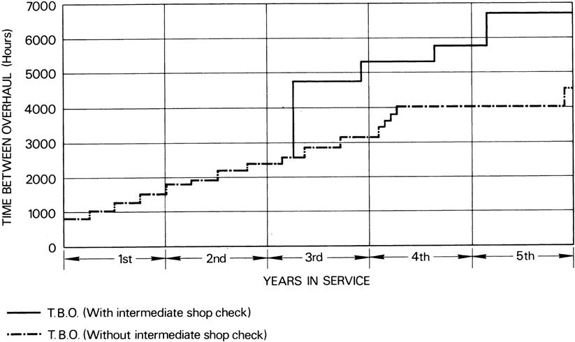
Among the main factors affecting the overhaul period for an engine is the use to which it is put in service. For example, a military engine will generally have a much lower TBO than its civil counterpart, as performance capability is the operating criterion rather than economics. Due to the effect of rapid temperature changes in the hot parts of the engine, the most arduous treatment is the frequent changing of power output to which short-haul transports and fighter aircraft are subjected.
When aircraft are based in areas with exceptionally high humidity or salt content in the atmosphere, there exists the added danger of corrosion, resulting in the need for more frequent overhauls. In peace time, some military aircraft have a very low utilization; this introduces the additional problem of certain materials used in its construction deteriorating before the engine has otherwise reached a condition that would normally require an overhaul. Elapsed time, as well as flying hours, would then influence the overhaul period.
In addition to scheduled overhauls, there are problems that arise from damage and defects. A proportion of these, which are uneconomic or impractical to rectify in the aircraft, necessitate unscheduled removals and require the engine to be returned to an engineering base or an overhaul shop for partial or complete overhaul.
The purpose of overhaul is to restore an engine enabling it to complete a further life by complying with new engine performance acceptance limitations and maintaining the same reliability. This is achieved by dismantling the engine in order that parts can be inspected for condition and to determine the need for renewal or repair of those parts whose deterioration would reduce the performance, or would not remain in a serviceable condition until the next overhaul.
The design of the modular constructed engine makes it particularly suited to a different technique of overhaul/repair. This technique is based on “on condition” monitoring. This means that a life is not declared for the total engine but only certain parts of the engine. On reaching their life limit, these parts are replaced and the engine returned to service, the remainder of the engine being overhauled “on condition.”
Modular construction, together with associated tooling, enables the engine to be disassembled into a number of major assemblies (modules). Modules that contain life-limited parts can be replaced by similar assemblies and the engine returned to service with minimum delay. The removed modules are disassembled into mini-modules for life limited part replacement, repair, or complete overhaul as required.
Overhaul/Repair Scope
The high cost of new engines has a considerable influence on the overhaul/repair arrangements, as the number of spare engines normally bought by the operator is kept to an absolute minimum. This means that an unserviceable engine must be quickly restored to serviceability by changing a module, or a part if the modular construction will permit it, or by careful scheduling of planned removals for overhauls at time expiry. This scheduling, through the workshop, of engines or modules that require the use of specialized equipment for repair is important, both to keep the flow of work even and to stagger removals to avoid aircraft being grounded by shortage of serviceable engines or modules.
Because the work that is to be implemented must be planned and subsequently recorded, the engine or module is received in the workshop with documents to show its modification standard and its reason for rejection from service. The planning will include a list of the modifications that can or must be incorporated to improve engine reliability or performance or to reduce operating costs.
The layout of the overhaul/repair workshop is designed to facilitate work movement through the complete range of operations, to achieve maximum utilization of floor space and to allow special equipment to be sited in positions that will suit the general flow pattern. All these considerations are aimed at achieving a quick turnaround of engines. As an example of how shop layouts may be planned, a typical arrangement is shown in Figure 12–10.
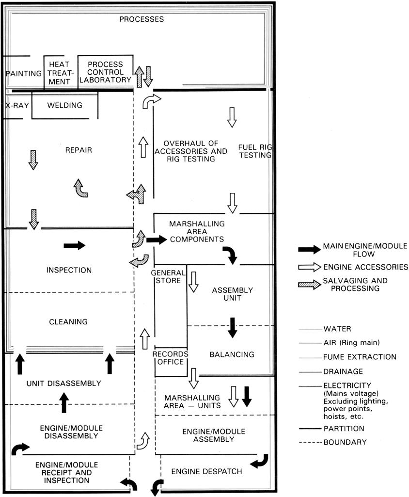
Disassembly
The engine can be disassembled in the vertical or horizontal position. When it is disassembled in the vertical position, the engine is mounted, usually front end downwards, on a floor-fixture stool or a ram-top fixture. To enable it to be disassembled horizontally, the engine is mounted in a special turnover stand.
When the floor-fixture stool is used, the personnel use a mobile work platform to raise themselves to a reasonable working position around the engine. When the ram-top fixture is used, the ram and engine are retracted into a pit, so enabling the workmen to remain at floor level.
The engine is disassembled into main sub-assemblies or modules, which are fitted in transportation stands and dispatched to the separate areas where they are further disassembled to individual parts. The individual parts are conveyed in suitable containers to a cleaning area in preparation for inspection.
Cleaning
The cleaning agents used during overhaul range from organic solvents to acid and other chemical cleaners, and extend to electrolytic cleaning solutions.
Organic solvents include kerosene for washing, trichloroethane for degreasing and paint stripping solutions that can generally be used on the majority of components for carbon and paint removal. The more restricted and sometimes rigidly controlled acid and other chemical cleaners are used for corrosion, heat scale and carbon removal from certain components. To give the highest degree of cleanliness to achieve the integrity of inspection that is considered necessary on certain major rotating parts, such as turbine discs, electrolytic cleaning solutions are often used.
Aircraft that operate at high altitudes can become contaminated with radioactive particles held in the atmosphere, this radioactivity is retained in the dirt and carbon deposits in the engine.
If contamination is suspected the radioactivity level of the engine must be determined to ensure the limitations agreed by the health authorities are not exceeded. Evidence of contamination will entail additional cleaning in a designated region, separate from the overhaul area, to safeguard the health of personnel in the workshop. Arrangements have to be made with the health authorities for disposal of the waste radioactive cleaning material.
Inspection
After cleaning, and prior to inspection, the surfaces of some parts, e.g., turbine discs, are etched. This process removes a small amount of material from the surface of the part, leaving an even matt finish that reveals surface defects that cannot normally be seen with the naked eye. The metal removal is normally achieved either by an electrolytic process in which the part forms the anode, or by immersing the part for a short time in a special acid bath. Both methods must be carefully controlled to avoid the removal of too much material.
After the components have been cleaned they are visually and, when necessary, dimensionally inspected to establish general condition and then subjected to crack inspection. This may include binocular and magnetic or penetrant inspection techniques, used either alone or consecutively, depending on the components being inspected and the degree of inspection considered necessary.
The non-dimensional inspections can be divided into visual examination for general condition and inspection for cracks. The visual examination depends on the inspector’s judgment, based on experience and backed by guidance from the manufacturer. Although the visual examination of many parts of the engine conform to normal engineering practice, for some parts the acceptance standards are specialized, for example, the combustion chambers, which are subjected to very high temperatures and high speed airflows in service.
Dimensional inspection consists of measuring specific components to ensure that they are within the limits and tolerances laid down and known as “Fits and Clearances.” Some of the components are measured at each overhaul, because only a small amount of wear or distortion is permissible or to enable the working clearances with mating components to be calculated. Other components are measured only when the condition found during visual inspection requires dimensional verification. The tolerances laid down for overhaul, supported by service experience, are often wider than those used during original manufacture.
The detection of cracks that are not normally visible to the naked eye is most important, particularly on major rotating parts such as turbine discs, since failure to detect them could result in crack propagation during further service and eventually lead to component failure. Various methods of accentuating these are used for inspection, the two principal techniques being penetrant inspection for nonmagnetic materials and electromagnetic inspection for those parts that can be magnetized.
Two forms of penetrant inspection in common use are known as the dye penetrant and the fluorescent test. With the dye test, a penetrating colored dye is induced to enter any cracks or pores in the surface of the part. The surface is then washed and a developer fluid containing white absorbents is applied. Dye remaining in cracks or other surface defects is drawn to the surface of the developer by capillary action and the resultant stains indicate their locations.
Fluorescent testing is based on the principle that when ultraviolet radiation falls on a chemical compound, known as fluorescent ink, it is absorbed and its energy re-emitted as visible light. If a suitable ink is allowed to penetrate surface cavities, the places where it is trapped will be revealed under the rays of an ultraviolet lamp by brilliant light emissions.
Magnetic crack testing (Figure 12–11) can only be applied to components that can be magnetized. The part is first magnetized and then sprayed with, or immersed in, a low viscosity fluid that contains ferrous particles and is known as “ink.” The two walls of a crack in the magnetized part form magnetic poles and the magnetic field between these poles attracts the particles in the ink, so indicating the crack (Figure 12–12). In some instances, the ink may contain fluorescent particles that enable their build-up to be viewed under an ultraviolet lamp. A part that has been magnetically crack tested must be de-magnetized after inspection.
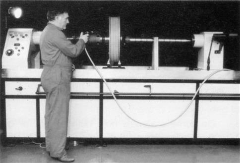

Chromic acid anodizing may be used as a means of crack detection on aluminum parts, e.g., compressor blades. This process, in addition to providing an oxide film that protects against corrosion, gives a surface that reveals even the smallest flaws.
When the requirement for a detailed inspection on a component such as a turbine disc is necessary, etching of the disc surfaces would be followed by binocular inspection of the blade retention areas. The whole disc would then be subjected to magnetic crack test, followed by re-inspection of the disc including a further binocular inspection of the blade retention areas.
Repair
To ensure that costs are maintained at the lowest possible level, a wide variety of techniques are used to repair engine parts to make them suitable for further service. Welding, the fitting of interference sleeves or liners, machining and electroplating are some of the techniques employed during repair.
Welding techniques are extensively used and range from welding of cracks by inert gas welding to the renewing of sections of flame tubes and jet pipes by electric resistance welding.
On some materials now being used for gas turbine engine parts, different techniques may have to be employed. An example of this is the high strength titanium alloys that suffer from brittle welds if they are allowed to become contaminated by oxygen during the cooling period. Parts made in these alloys, which have to withstand high stress loadings in service, are often welded in a bag or plastic dome that is purged by an inert gas before welding commences.
More advanced materials and constructions may have to be welded by electron-beam welding. This method not only enables dissimilar metals to be welded, but also complete sections of the more advanced fabricated constructions, e.g., a section of a fabricated rotor drum, to be replaced at a low percentage cost of a new drum.
Some repair methods, such as welding, may affect the properties of the materials and, to restore the materials to a satisfactory condition, it may be necessary to heat treat the parts to remove the stresses, reduce the hardness of the weld area or restore the strength of the material in the heat affected area. Heat treatment techniques are also used for removing distortions after welding. The parts are heated to a temperature sufficient to remove the stresses and, during the heat treatment process, fixtures are often used to ensure the parts maintain their correct configuration.
Electroplating methods are also widely used for repair purposes and these range from chromium plating, which can be used to provide a very hard surface, to thin coatings of copper or silver plating, which can be applied to such areas as bearing locations on a shaft to restore a fitting diameter that is only slightly worn.
Many repairs are effected by machining diameters and/or faces to undersize dimensions or bores to oversize dimensions and then fitting shims, liners, or metal spraying coatings of wear resistant material. The effected surfaces are then restored to their original dimensions by machining or grinding.
The inspection of parts after they have been repaired consists mainly of a penetrant or magnetic inspection. However, further inspection may be required on parts that have been extensively repaired and this may involve pressure testing or X-ray inspection of welded areas.
Re-balancing of the main rotating assembly will be necessary during overhaul, even though all the original parts may be refitted, and this is done as described next.
Balancing
Because of the high rotational speeds, any unbalance in the main rotating assembly of a gas turbine engine is capable of producing vibration and stresses that increase as the square of the rotational speed. Therefore very accurate balancing of the rotating assembly is necessary.
The two main methods of measuring and correcting unbalance are single plane (static) balancing and two-plane (dynamic) balancing. With single plane, the unbalance is only in one plane, i.e., centrally through the component at 90° to the axis. This is appropriate for components such as individual compressor or turbine discs.
For compressor and/or turbine rotor assemblies possessing appreciable axial length, unbalance may be present at many positions along the axis. In general it is not possible to correct this combination of distributed unbalance in a single plane. However, if two correction planes are chosen, usually at axially opposed ends of the assembly, it is always possible to find a combination of two unbalance weights that are equivalent for the unbalances present in the assembled rotor, hence two plane balancing.
To illustrate this point refer to Figure 12–13, the distribution of unbalance in the rotor has been reduced to an equivalent system of two unbalances “A” and “B.” The rotor is already in static balance because in this example “A” and “B” are equal and opposed. However, when the part is rotating, each weight produces its own centrifugal force in opposition to the other causing unbalance couples, with the tendency to turn the part end-over-end. This action is restricted by the bearings, with resultant stresses and vibration. It will be seen, therefore, that to bring the part to a state of dynamic balance, an equal amount of weight must be removed at “A” and “B” or added at “P” and “O.” When the couples set up by the centrifugal forces are equal, it is said that a part is dynamically balanced. Unbalance is expressed in units of ounce-inches, thus 1 ounce of excess weight displaced 2 inches from the axis of a rotor is 2 ounce inches of unbalance.
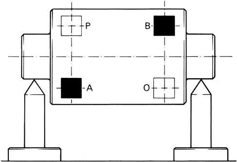
When balancing assemblies such as L.P. compressor rotors, the readings obtained are inconsistent due to blade scatter. Blade scatter is caused by the platform and root or retaining pin clearances allowing the blades to interlock at the platforms and assume a different radial position during each balancing run. This only occurs at the relatively low rpm used for balancing, because, during engine running, the blades will assume a consistent radial position as they are centrifuged outwards.
To obtain authentic balance results when blade scatter is present, it is necessary to record readings from several balance runs, e.g., eight runs, thereafter determining a vector mean.
A typical dynamic balancing machine for indicating the magnitude and angular position of unbalance in each plane is shown in Figure 12–14. Correction of unbalance may be achieved by one or a combination of the following basic methods: redistribution of weight, addition of weight, and removal of weight.
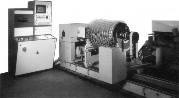
Redistribution of weight is possible for such assemblies as turbine and compressor discs, when blades of different weight can be interchanged and, on some engines, clamped weights are provided for positioning around the disc.
The addition of weight is probably the most common method used, certain parts of the assembly having provision for the fitting of screwed or riveted plugs, heavy wire, balancing plates, or nuts.
Removing weight by machining metal from balancing lands is the third basic method, but normally it is only employed on initial manufacture when balancing a component, e.g., a turbine shaft or a compressor shaft, that is part of a larger assembly.
Modular assembled engines demand different balancing methods that include the use of simulated engine rotors. The dummy rotors must reproduce the bearing span, weight, center of gravity and dynamic characteristics of the sub-assembly it replaces and be produced and maintained so that their own contribution to the measured unbalance is minimal. In order to obtain the correct dynamic reactions when balancing a compressor and/or turbine rotor assembly on its own, with the intention of making it an independent module, a simulated engine rotor must be used to replace the mating assembly (Figure 12–15). The compressor and/or turbine rotor assembly having then been independently balanced with the appropriate dummy rotor is thus corrected both for its own unbalance and influence due to geometric errors on any other mating assembly.
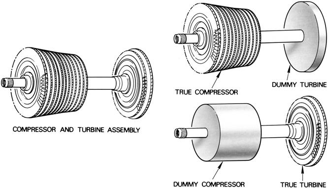
Moment Weighing of Blades
With the introduction of the large fan blade, moment weighing of blades has assumed a greater significance (Figure 12–16). This operation takes into account the mass of each blade and also the position of its center of gravity relative to the center line of the disc into which the blade is assembled. The mechanical system of blade moment weighing may be integrated with a computer, shown in Figure 12–17, which will automatically optimize the blade distribution. The moment weight of a blade in units, i.e., g.mm. or oz.in., is identical to the unbalance effect of the blade when installed into a disc. The recorded measurement of blade moment weights enables each blade to be distributed around the disc in order that these unbalances are cancelled.
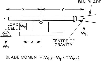
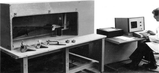
Assembling
The engine can be built in the vertical or horizontal position, using the ram or stand illustrated in Figures 12–18 and 12–19, respectively. Assembling of the engine sub-assemblies or modules is done in separate areas, thus minimizing the build time on the build rams or stands.
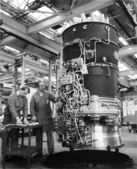
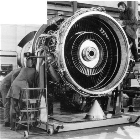
During assembling, inspection checks are made. These checks can establish dimensions to enable axial and radial clearances to be calculated and adjustments to be made, or they can ascertain that vital fitting operations have been correctly effected. Dimensional checks are effected during disassembly to establish datums that must be repeated on subsequent re-assembly.
To ensure that the nuts, bolts, and setscrews throughout the engine and its accessories are uniformly tight, controlled torque tightening is applied, Figure 12–20, the torque loading figure is determined by the thread diameter and the differing coefficients of friction allied with thread finish, i.e., silver or cadmium plating and the lubricant used.
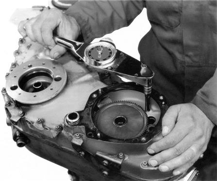
Testing
On completion of assembly, every production and/or overhauled engine must be tested in a “sea-level” test cell (Figure 12–21), i.e., a test cell in which the engine is run at ambient temperature and pressure conditions, the resultant performance figures being corrected to International Standard Atmosphere (I.S.A.) sea-level conditions.

To ensure that the engine performance meets that guaranteed to the customer and the requirements of the government licensing and purchasing authorities, each engine is tested to an acceptance test schedule.
In addition to the “sea-level” tests, sample engines are tested to a flight evaluation test schedule. These tests cover such characteristics as anti-icing, combustion and reheat efficiencies, performance, mechanical reliability, and oil and fuel consumptions at the variety of conditions to which the engine may be subjected during its operational life. Flight evaluation testing can be effected by installing the engine in an aircraft or in an altitude test cell (Figure 12–22) to test the variations of air humidity, pressure and temperature on the engine, its accessories and the oil and fuel systems. When in an aircraft, the engine is operated at the actual atmospheric conditions specified in the schedule, but in an altitude test cell, the engine is installed in an enclosed cell and tested to the schedule in conditions that are mechanically simulated.
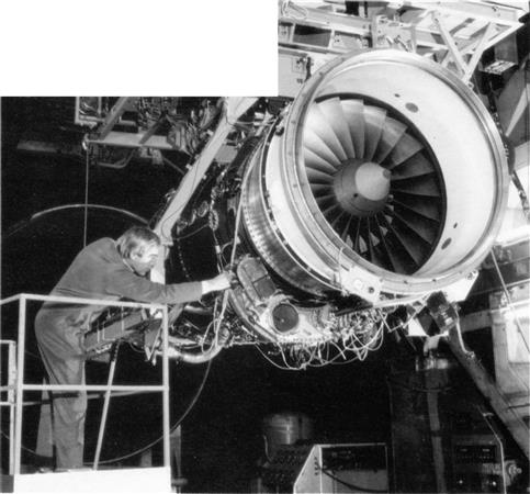
Mechanical simulation comprises supplying the engine inlet with an accurately controlled mass airflow at the required temperature and humidity, and adjusting the atmospheric pressure within the exhaust cell to coincide with pressure at varying altitudes.
The data that are accumulated from either “sea-level” or altitude testing are retained for future development, engine life assessment, material capabilities, or any aspect of engine history.
During the testing of turbo-jet engines there is a need to reduce the exhaust noise to within acceptable limits. This may be achieved by several different means, each involving costly equipment. However, a typical silencer would do this by expansion in the first section, damping by acoustic tubes and final diffusion by a large exit through which the hot gas would be directed upwards at a low velocity.
Preparing for Storage/Dispatch
The preparation of the engine/module for storage and/or dispatch is of major importance, since storage and transportation calls for special treatment to preserve the engine. To resist corrosion during storage, the fuel system is inhibited by special oil and all apertures are sealed off. The external and internal surfaces of the engine are also protected by special inhibiting powders or by paper impregnated with inhibiting powder and the engine is enclosed in a re-usable bag (Figure 12–23) or plastic sheeting into which a specific amount of desiccant is inserted. If transportation by rail or sea is involved, the inhibited and bagged engine may be packed in a wooden crate or metal case.
Major Repair and Overhaul Case Studies20
The preceding material gives the reader the basic framework with which to develop R&O strategy. Consider also that, with modern gas turbines, the actual technology development that occurs around this framework is rather detailed as the following cases prove.
As occurs elsewhere in this book, certain cases lend themselves to inclusion in the chapter on maintenance, repair and overhaul (Chapter 12), as well as the chapter on performance, performance testing and optimization (Chapter 10). An interest in either chapter is better explored by reading both. For all these cases, as elsewhere in this book, the reader ought to contact the original source of the case to get more detail than I elected to include here.
Case Study 9 deals with the role of metallurgical analysis in gas turbine maintence, and is written by a metallurgical repair facilty. A self-evident connection to some operators, the case provides specifics on cases where selective metallurgical analysis has helped determine component lives or TBO.
Case Study 10 describes the painstaking development of repairs for “F” technology by an independent facility. The case includes considerable discussion on coatings that certain “F” technology machines used extensively. This gives the reader a good appreciation of the investment and the lead time required to develop reliable repairs. It also explains how good repairs can greatly extend the component lives of gas turbine engines.
Case Study 11 describes the details of some power metallurgy repairs with examples from an independent facility that developed a proprietary process for this technology. Again, this illustrates what a difference innovative repair technology can make to an end user’s costs per fired hour.
Case Study 12 presents an OEM’s (Siemens AG) strategy with extending the life of specific hot section components used in power generation applications.
Case Study 13, written by an EPC contractor (sometimes responsible for operation of a plant for a client), deals with “Assessing performance degradation in gas turbines for power applications.”
Case Study 14, written by a metallurgical repair facility, entitled “Remaining Life Assessment of Power Turbine Disks,” which discusses how component geometry and fluid flows can affect the individual lives of components that are identical by model number.