Gas Turbine Major Components and Modules
Abstract
This chapter focuses on how intimately financial considerations shape a gas turbine’s components. A basic explanation of the primary hardware is followed by some detailed design cases. Specification of a gas turbine and gas turbine system that then fits its working role well require understanding of all hardware components technically and economically (including life cycle usage, spares costs, and repair costs); knowledge of case histories that point out potential benefits and pitfalls for one’s own application; and the economics of the above two factors and how they form the overall “cost per fired hour” figures for a given application. The factor that determines the best gas turbine OEM (original equipment manufacturers) “sellers” is the strength of their financial services offered.
Keywords
Primary module basics; combustors; compressors; flameless combustor; life cycle; economics; design; hardware components
“We are what we repeatedly do. Excellence then, is not an act, but a habit.”
—Aristotle
Economics Dictates Design1
Although this is not intended to be a chapter on the business economics of gas turbines, it would be unfair to not point out to the reader how intimately financial considerations literally shape a gas turbine’s components. A basic explanation of the primary hardware is followed by some detailed design cases, but these first pages provide the economic frame of mind to fully appreciate those cases.
Specification of a gas turbine and gas turbine system that then fits its working role well requires:
• Understanding of all hardware components technically and economically (including life cycle usage, spares costs, and repair costs)
• Knowledge of case histories that point out potential benefits and pitfalls for one’s own application
• The economics of the above two factors and how they form the overall “cost per fired hour” figures for a given application
In the working lifetime of anyone alive today, gas turbines will be a major and growing player in 80% of the global economy (power generation, process industries, energy, and fuels). They will increase their currently small role in the remaining 20% (domestic sector) of the economy. Factors that currently limit their more widespread use are:
• The global abundance of coal
• The global glut of residual fuel that only a handful of gas turbine models can burn successfully
• Other favored forms of power generation such as hydro (in countries rich in this resource such as Sweden and Canada) and nuclear power (in fuel-poor countries such as Japan)
• The slow rate of technology development with using pulverized coal or some form of coal gas “mined” from coal seams as a fuel for gas turbines
The factor that determines the best gas turbine OEM (original equipment manufacturers) “sellers” is the strength of their financial services offered. In financial services, GE is the undisputed leader and the size of its fleets, particularly in newly developing countries, prove this. Other OEMs have formed successful joint ventures with foreign national power companies, countries, and banks. The bottom line is that if the customer does not have sufficient financial resources, an OEM’s
• Willingness to countertrade, as well as
• Political muscle in the United States and international terms
weigh much heavier in the machinery selection process than they would with an end user who can easily afford to pay for his gas turbine systems. These end users’ list of highest consideration factors generally includes the gas turbine system’s cost per fired hour.
There are many factors that make up the value of cost per fired hour. They include:
• Fuel costs, including fuel efficiency considerations
• Design features, such as thrust bearing selection, aerodynamic losses, that may account for considerable power loss
• The signing of any “power by the hour” contracts with the OEM
• Warranty package costs (often hidden in the initial capital cost of the turbine package)
• Personnel training (also often hidden in the initial capital cost)
• Type of initial contract (BOOT and other options, see Chapter 15 in this book) with the OEM
• Fuel purchase contract and considerations such as whether the fuel supplier is also the turbine package owner and operator)
• Regular O&M, including considerations for ease of operation and operator skill level required
• Costs of spares, including spares in stock availability, potential for repair of components
• Regulatory costs (including lost efficiency with antipollution devices)
• Costs incurred with OEM model consolidation (for example, discontinuing a model to reduce stocking spares and “duplicating” the old model’s place by replacement with an existing model and a gearbox, obliging the user to absorb the 2–3% power loss)
Typically, although OEMs consider all of the above factors, they are biased towards the first three, the first two of those because that involves their technical expertise and product pride. The third (power by the hour) is where an OEM can turn a healthy profit. These contracts are on the increase because many gas turbine operators, particularly in the power patch and fuels business, are starting not to maintain high levels of in-house turbine expertise. If it is to an OEM’s benefit to install new spares instead of concentrate on repair development, he can do so more easily with a power by the hour contract.
How all these considerations turn out depends to some extent on what the turbine, and more specifically the turbine components, offers in terms of design performance. Design and performance is what OEMs market; and the other, often more valid, business considerations are hammered out in negotiation phases. And so gas turbine designers strive for every small improvement with basic hardware. Most design specialists spend entire lifetimes with just one component, so their individual targets may include increased pressure ratio on the compressor, higher TITs (turbine inlet temperatures), more heat-resistant first stage nozzle guide vane metallurgy, higher thrust to weight, or power/weight ratios.
Eventually, every design feature is a compromise. Higher TITs will require more cooling features. The extent to which that happens (or not) will mean higher capital cost and fired costs per unit of power. More cooling air than the absolute minimum dictated by conventional design then reduces efficiency. The OEM’s marketing staff, depending on which OEM’s design philosophy we are talking about, may not appreciate that. So the end user may not always agree with the OEM on the priorities exercised at that decision point. Those few decimal points or more of efficiency may be a price the end users pay in blood, if a combination of operational circumstances should need more cooling air than the OEM calculated. Additional cooling air can make the difference between a pilot with a demanding and unpredictable mission profile (like a military fighter pilot) getting home safely or not.
And so the numbers of knowledgeable end users diminish as increases occur in the number of power by the hour contracts and OEMs who are also power plant owners or non-OEM asset managers of some sort. The few that are left battle for their share of input into OEMs’ final designs, with their respective priorities. Those may, for instance, include:
• Reliability and availability (a few efficiency points squeezed out of any model “in trade” mean little to an end user if he’s a remote arctic operator who needs an uninterruptible power supply or a marine operator who hopes to not have to dock for several months)
• The ability to derate for lower TITs (he may need longer lives for his hot section components and a cooler operating turbine if he’s in a distant and isolated desert)
Priorities vary. An end user may be thrilled to gain 0.1% efficiency on the turbine module of his Frame 7, if it means he “gains” $700,000 in fuel costs per turbine, or he may not care if he’s an oil sheik with bottomless oil wells. The sheik may opt for derated, less efficient operation, if he still gets what his personal refinery needs. If he cannot get any additional profit by selling power excess to the national grid, derating may mean his turbine assets then need fewer trips to the nearest overhaul shop in Scotland.
A customer in a Southeast Asian country whose laws dictate “BAT” (best available technology) as opposed to specific NOx emission volumes in ppm would be happy to settle for an OEM that offers a single-burner silo combustor over one with multiple burners that offers better temperature distribution and lower NOx production. If and when environmental regulations in that country tighten (Korea, China, and Taiwan have incrementally tightened their environmental standards over the past decade), the single-burner OEM then has the opportunity to sell a low NOx multiburner retrofit or a water or steam injection system. The end user then has to deal with the requirement for boiler feedwater quality for the injection system, but if he is a combined cycle operator, he already has that at this disposal. As did a chemical plant in Thailand (which had a steam source from another process) looking at the potential for getting another 20,000 horsepower out of its five older model GE Frame 5s in a physical location where it did not have enough real estate to place another machine. When properly designed, steam injection can result in 20–30% additional horsepower. Or, depending on the design, only NOx reduction may result.
Sometimes, gas turbines owe the size of the global fleet of any one model to the year of their market entry. The world has a large fleet of Solar Saturn and Centaur gas turbines and gas turbine-compressor trains. When these models made their debut some decades ago, their current competitors, such as the smaller models made by what was part of Alstom (formerly European Gas Turbine, formerly Ruston), were not yet a financially backed glimmer in any designer’s eye. Solar also helped its market share with the feature of several readily available (if expensive) rental units in the event of required removals.
This commanding market share fostered a tendency to pass on design development costs to the end user to an extent that many considered unfair. The earliest model of the Centaur delivered a nominal 3300 hp. When Solar designed uprate packages to deliver 3500 and 3800 hp, the customer base that depended on Solar to do its overhauls were obliged to buy the higher-hp kits. Customers complied for the most part, faced with nonwarranty of any overhaul and the fact that Solar did not wish to support the earlier components any longer than they could be changed out during overhaul. End-user pressure started to make itself felt at about the start of the 1980s and Solar evolved to a far more end-user-responsive OEM. Solar then extended its product range with larger and more efficient models in land-based power generation and mechanical drive application, to rival those of other OEMs. Meanwhile, the old Centaur and Saturn fleets continue operation to this day. Not models of optimized efficiency, they are rugged enough to have lasted all these decades, and many of their owners are faced with declining production in the fields the machinery was meant to tap.
Sometimes, a global gas turbine fleet owes its size in part to the financial genius and deep pockets of the OEM in question. One OEM, to secure a large sale to an aviation customer in China, paid the customer a 4% fuel efficiency shortfall (compared with the nearest OEM competitor) over the stated life of the engines (20,000–25,000 pound thrust size). In other words, that OEM gave away the initial capital expenditure to the end user. It was a shrewd and calculated move. The winning OEM’s inlet geometry had much lower FOD resistance. A 2-pound pigeon had been observed to “corncob” one of their engines as far back as the final turbine stages. The unsuccessful rival had a wide chord fan blade and bypass annulus features that had, on one occasion, ingested a 24-pound vulture on landing approach, broken two fan blades (and essentially little else), and kept on running.
All of this serves to underline a few salient action items (if the end user does not already practice them):
1. Even if it does not directly affect daily operations, regard all detailed technical knowledge gained (such as from the cases in this chapter) as the potential basis for future negotiation in after-sales business with an OEM.
2. Join end-user groups, participate, and help sponsor to any extent possible their annual meetings. The end-user groups are varied and several. A few examples follow. (If “your” group is not mentioned below, the Internet and other end users will be able to tell you.)
• The GTUA (Gas Turbine Users Association) is a land-based applications end-user group. Its applications are predominantly mechanical drive and pipeline related. Every second year, it has a separate meeting for OEMs to provide feedback. With GTUA, there are separate meeting rooms for each discussing each OEM's turbines.
• Power-generation users have a vastly more specific agenda. They have separate groups per model of any specific OEM. The membership, particularly in the United States (which is where most of the meetings are held), consists of large and powerful utilities. All end-user groups theoretically exclude OEMs from “rap” sessions, where they are tabling complaints about them. However, the twist to this, given the acquisitions climate fostered during the 1990s, is that OEMs frequently today own, or partially own, and operate power plants. They are often their own end user.
• Similarly, large oil companies are becoming IPPs (independent power producers) at an increasing rate, so they can buy their own fuel in a fuel purchase agreement (FPA) that they orchestrate. About 20 years ago, the main reason for a large oil company producing its own power was because of potential required power shortfall in remote locations. Oil companies and refineries today can also get tax rebates (in countries such as Thailand that encourages any IPPs, small and large) for supplying their excess power to the grid. So the line between the two preceding groups of end users is blurring.
• The militaries of the Western world run their own formalized CIPs (component improvement) meetings for aircraft engines. Adjacent nations may attend the same meetings depending on the relative size of the military branch. For instance, the relatively small Canadian Forces helicopter fleets that serve much the same purpose as the U.S. Coast Guard do in the United States, join them for their meetings.
3. Scrutinize (if you are an end user) OEM service bulletins (SBs) whether mandatory, optional, or “campaign,” for applicability to your operation.
4. Consider item 3 in the light of your extended business plans. When Shell decided on the best harvesting options for its Brent field, it decided to let the deposits of light ends depressurize, so that they could be extracted as gas. At that decision point, it opted to retrofit more sophisticated instrumentation packages (non-OEM supplied, but OEM qualified source) on existing turbine packages.
5. Shell also gained considerable sophistication with life cycle assessment (LCA) of major gas turbine components in the process of doing 4, and the ability to extend certain component lives by as much as 100% or more. In other words, it pays to know your package accessories and instrumentation as well as your gas turbine components and view them all as an integral system.
6. Learn the design priorities of individual OEMs, and therefore their inherent weaknesses and strengths: the “raise efficiency by raising TITs and be as stingy with the cooling air as possible” group, the “same tooling function for a smaller premium” (and when this works, one saves a great deal of money) types, the “excess cooling air and rugged FOD resistant design” school, the guys whose oil system always works. This gets particularly interesting with joint venture products, where different OEMs design different modules, interfaces, and common-to-all-module systems. Sometimes this division of responsibility works in the endusers' favor, in that it contributes to reduced costs per fired hour.
7. Expect that reliable gas turbine workhorses will still be around several decades hence, albeit heavily tweaked and individually modified. One good example of this is the old GE Frame 5. GE recently released a “new version” of this old and beloved model. However, owners of the old version will not give up their machines. The “tweaked and individually modified” occurs when existing machines do not, for any reason, meet fleet standards. Take the French power facility that had its Frame 5 fleet developing premature cracks in their turbine discs. An external consultant designed the steam injection that took the discs out of danger of cracking (and gave the old machines a 20% additional power bonus). Also the metallurgy of these old machines makes them relatively easy to repair (by welding or heat treating).
8. Be aggressive in learning from experience in different applications of “your” engine. For instance: The GE LM2500 fleet is a vast one, in power generation, mechanical drive, and marine service. The land and marine end-user base benefited from the fact that the LM2500 is essentially a GE CF6 80C2 “sitting” on land or the sea. The Rolls Royce RB211, Trent, and Avon fleets benefit similarly. The additional number of operating hours in a different environment with demands of its own may increase the overall expertise the end users have to draw upon. For instance: The question posed by land users of LM2500’s additional required systems for high vanadium content in fuel was preceded by NATO studies done on the same question on behalf of the naval military LM2500 fleet. Another example: The recent “revolutionary” development of injecting fuel into already fuel-rich exhaust gases of a power generation system and reigniting the mix for power augmentation is essentially a “grounded” afterburner.
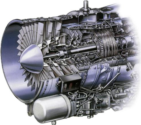
The source of the basic detailed component information that follows is Rolls Royce (RR). This section is based on one of their aviation engine models, which is appropriate, given the sophisticated nature of aeroderivatives in land and marine use as well as new industrials. The newer models are “officially” called by the same designation with RR only because they are just as sophisticated as a flight engine in terms of metallurgy or instrumentation systems.
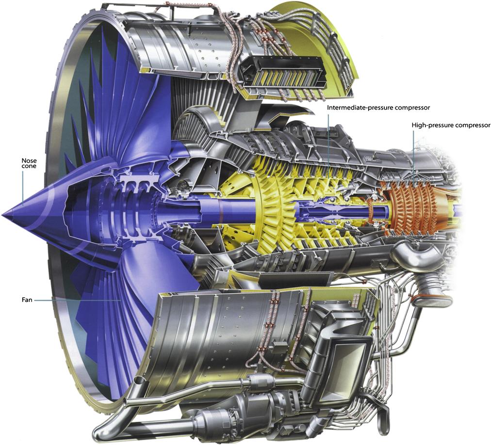
Gas Turbine Engine Modules
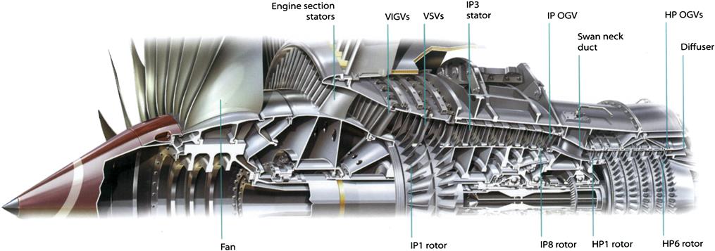
Rotor Support Structures
Fundamentally, the engine outer structure is a pressure vessel that contains hot, flowing air. The rotor support structures extend inside the pressure vessel to support the rotating components of the engine while allowing air to pass through from front to rear. They are generally circular, with a number of struts or vanes joining the inner and outer rings and a bearing housing located in the middle. Inside the bearing housings, the bearings allow free rotation, yet precise centering, of the rotors. On the outside, support structures may provide mounting lugs as attachment points for external engine components or the engine-to-aircraft mounting. Some lugs also transmit engine thrust loads to restrain forward and reverse motion. The support structures are joined together by compressor or turbine casings to form a complete support frame for the engine.
Each engine rotor requires two or even three rotor support structures; however, a single support structure like the intercase can be used for up to three rotors. Because of this, the RB211 and Trent engines need only four structures to support the three rotor systems.
The engine rotors transmit loads generated by the rotors to the stationary engine structure through the rotor support structures. The outer engine structure collects the loads and transfers them to the aircraft at the engine mounts. When an aircraft performs maneuvers, the structures maintain the centering of the engine rotors. In the event of a component failure, the structures ensure that the engine will not create a hazard to the aircraft, although the engine may stop operating.
The rotor loads enter the support structures at the bearings, which are inside an annulus of flowing air. Struts or vanes transmit the loads through the gaspath to the outer stationary structure of the engine. Both struts and vanes minimize disruption and pressure loss in the gaspath, but vanes are more sophisticated, and are used to significantly redirect the air/gas. The struts or vanes also provide a path for lubricating oil to be provided to, and returned from, the bearing chambers.
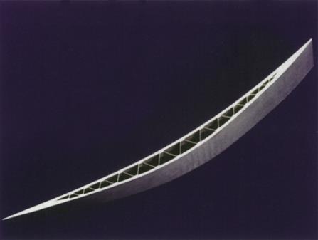
Each structure must withstand a wide range of extreme conditions to ensure the engine's safe and reliable operation. In an aircraft engine, weight must be stringently controlled. Jet engines for aircraft propulsion use the lightest possible materials. In cooler locations, light alloys such as aluminum or magnesium perform well. For moderate temperatures, titanium, though expensive, provides the necessary qualities of high strength, low weight, and temperature. In the very hottest locations, heavy materials such as nickel alloys provide sufficient temperature resistance. To ensure the most structurally efficient configurations, engineers use extensive Finite Element Analysis to evaluate the ability of the structures to withstand engine and aircraft loads. (See figures 4–2 and 4–3).
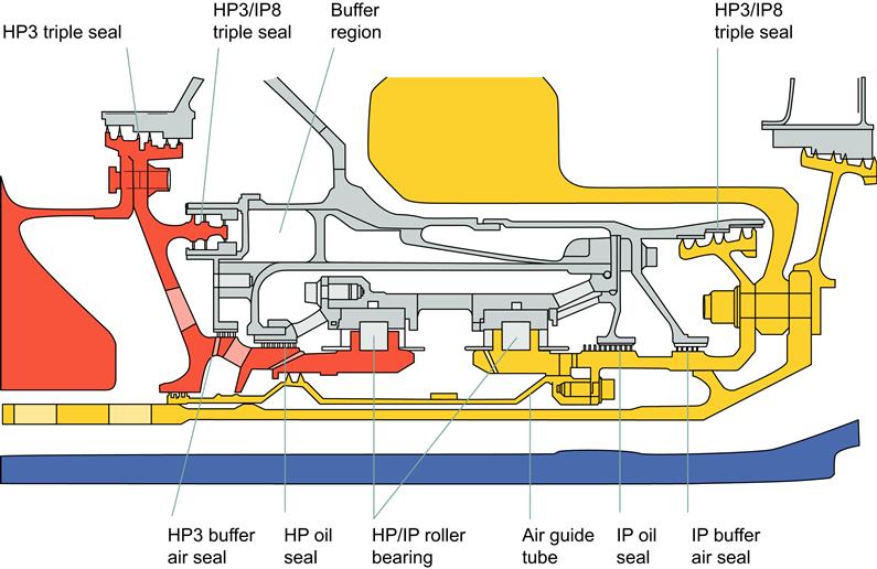
The innermost part of the support structure is the bearing chamber, which provides a favorable environment for the bearings. Inside, oil nozzles distribute lubrication to the bearings and gears. Around the shafts, labyrinth seals prevent the oil from leaking out and limit the amount of hot air entering the chamber. Buffer air at higher pressure surrounds the bearing chambers outside the labyrinth seals so that air flows inward through the seals. This inward flow of buffer air prevents oil from migrating out of the labyrinth seal.
Several engine families use a four-rotor support structure, which includes:
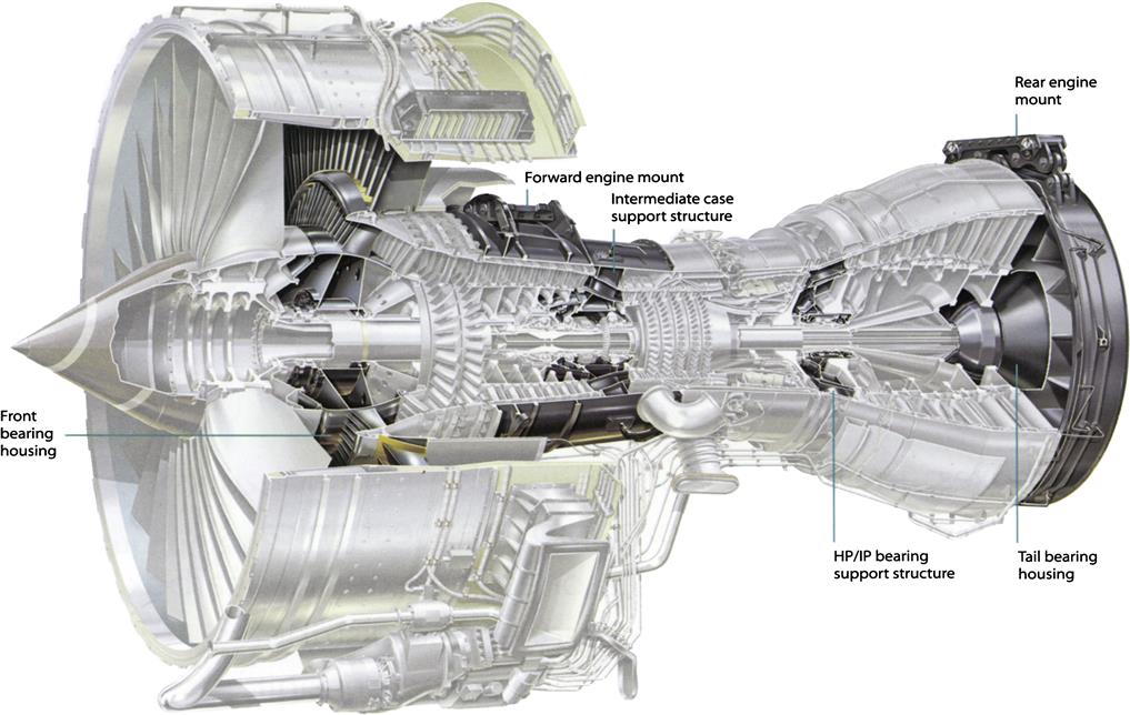
Front Bearing Housing
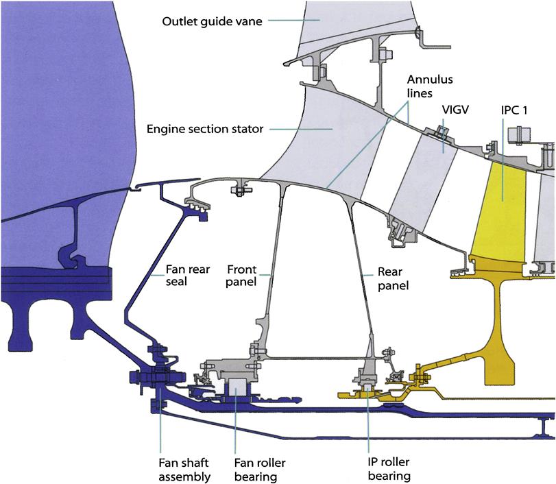
The front bearing housing (FBH) provides support near the front of the fan rotor (also known as the low-pressure or LP rotor) and at the front of the intermediate-pressure (IP) rotor. The bearing chamber on the inside contains the forward LP and IP roller bearings. The engine section stator (ESS) vanes direct a portion of the fan airflow into the core of the engine and carry structural loads to the splitter area. Two conical panels attach the ESS vanes to the bearing chamber. The ESS structure is manufactured as either a machined cast ring of vanes, or built up from individual forgings that are welded together to form a ring. In addition to structure, the ESS ring provides:
Intermediate Case
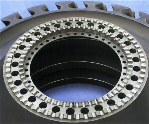
Also called the intercase, this is a structure between the HP and IP compressor cases, which houses the main shaft thrust bearings and carries the rotor gas loads through struts to the engine casing and thrust mounts. It also houses the internal gearbox, which incorporates a bevel-gear drive shaft linking the HP rotor to the external gearbox. The intercase provides support for all three rotor systems. Thrust bearings contained in the intercase bearing chamber, away from the hot end of the engine, provide mid-rotor support for the LP and IP rotors, and forward support for the HP rotor. These bearings transmit all of the axial forces of the rotors to the engine structure. On Trent and RB211 engines, lugs on the intercase transmit the engine thrust to the nacelle structure. Therefore, unlike the other rotor support structures, the intercase must be strong in the axial direction as well as the radial direction. The intercase, therefore, literally pulls the aircraft through the air.
Because of the location of the intercase at the forward end of the HP rotor, it is called upon for an additional and unique function. It provides an internal gearbox in the bearing chamber to transmit power to and from the HP rotor. This is necessary for engine starting and to drive mechanical units such as oil pumps and generators that are mounted on the engine. The internal “gearbox” includes a pair of bevel gears mounted within the intercase. One gear is mounted on the HP rotor; its mating gear is connected to a small shaft that runs through a strut. This small shaft is the radial drive, which is part of the system that transmits mechanical power to and from the external gearbox. (See figure 4–4).
As in all rotor support structures, the intercase contains a passage for the engine's core airflow. This passage is known as a “swan neck” duct, because it sweeps from the larger radius of the IP compressor exit to the smaller radius of the HP compressor inlet, giving the appearance of a swan neck on drawings. Struts to carry structural loads across the flowpath span the swan neck. The hollow struts in the swan neck duct allow oil services to, and venting from, the bearing chamber, as well as a place for the radial drive. The structure is usually cast titanium with some amount of welding necessary due to the complexity of the structure.
HP/IP Structure
The HP/IP turbine bearing support structure is located between the HP and IP turbine discs to provide support to the aft end of the HP and IP rotors. The bearing chamber houses the HP and aft IP roller bearings. The structure transmits radial bearing loads through the hub and into the outer casing. This structure operates in a very challenging environment. It is surrounded by very hot engine parts and must carry load through the HP turbine exit airflow, which is one of the hottest parts of the engine. Struts connect the inner structure to the turbine case while allowing air to pass. In this environment, the only fluid available for cooling is the oil supply, which must pass through the hot flowpath along with the struts. Due to their interaction with the outer casings, the bearing support structure has a major influence on the control of blade tip clearances and shaft dynamics. The bearing support structure, therefore, must have sufficient stiffness to withstand extreme maneuvers, while maintaining an adequate fatigue life.
The blade tip clearances are further influenced by the use of an oil squeeze film damper. The damper consists of a narrow oil-filled gap between the bearing outer race and the bearing chamber structure. The rotor system, though precisely balanced, will still have unbalance present. The damper provides fluid support for the bearing race in a way that allows the rotor system to rotate about its true mass center. In addition, the fluid film reduces the unbalance forces transmitted to the structure. The bearing chamber components operate near the maximum permissible limits for bearings and engine oil. Typically, nickel alloys are the materials used to make the housings, shafts, support structures, and air seals for high bypass three-shaft engines.
Tail Bearing Housing
The tail bearing housing is the bearing chamber that supports the aft end of the LP rotor and contains the rear engine mounts. Exit guide vanes provide structural support of the bearing chamber and provide the pathways for oil, air, and instrumentation cables. The exit vane shape is simpler than the FBH ESS vanes because they need to provide less turning of the airflow.
The rear-bearing chamber provides a protected environment, housing the LP shaft rear roller bearing and LP turbine over-speed probe. Roller bearings transfer radial loads into the structure. Oil transfer routes through the exit vanes provide oil lubrication, scavenging, and an oil film damper.
Although the tail bearing housing must operate in the environment of the LP turbine exhaust, it is not as severe as that endured by the HP/IP support. Due to the prevailing high temperatures from the turbine, the structure material is a nickel alloy. In the quest for lower production costs, manufacturing methods have varied between a fully cast structure to a fabricated structure, but both methods have proven comparable. The bearing chamber housing is traditionally manufactured from cast steel alloy, but has also been made from cast nickel alloy.
Fan Module Basics
The primary modules in a gas turbine are the:
A gas turbine also has an inlet section/module and an exhaust section/module (see Figure 4–5).
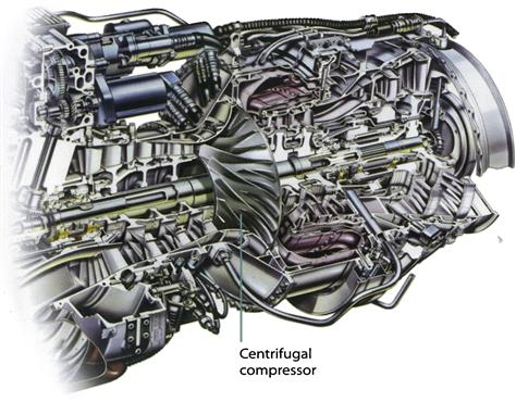
Most advanced and large gas turbines have compressors that are of the axial design type. Some of the earlier, smaller, or deliberately compact gas turbines have centrifugal compressors (see Figures 4–6, 4–7, and 4–8).
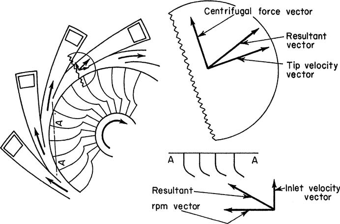
Each compressor stage provides an opportunity for stepping up the overall compressor pressure ratio (PR), so although an axial stage may not offer as much of a PR as a centrifugal stage of the same diameter, a multi-stage axial compressor offers far higher PR (and therefore mass flow rates and resultant power) than a centrifugal design (see Figures 4–7, 4–8, and 4–9).
Therefore, most gas turbine designs incorporate axial compressors. In newer designs, the compressor and turbine modules may be split into further submodules to lessen the stress on individual components and achieve better efficiencies.
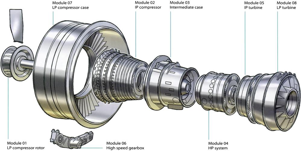
So a compressor may have a low-pressure (LP) module, or LPC, and a high-pressure module (HPC). In this case, there will be equivalent high- and low-pressure turbine modules (LPT and HPT). The LPC and LPT will operate on one long shaft at the same speed. The HPC and HPT will operate on a shorter shaft that fits around, and is concentric to, the low-pressure shaft and is at a higher speed than the low-pressure module (see Figure 4–5).
Some contemporary gas turbines have three modules in their compressor and turbine sections, designated low, intermediate, and high pressure, each with their own shaft. This modular concept allows for module replacement or exchange, if maintenance to a module is required, without taking the entire gas turbine out of service.
The Nose Cone
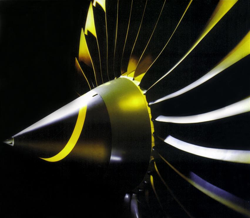
The nose cone provides the inner annulus profile in front of the fan for smooth airflow into the fan blades' roots and must withstand bird impact, erosion, and the build-up of ice. To meet this functionality, the cone is made from glass fiber, laid and curved so that the cone achieves maximum strength. The thickness of the cone is based on the experience of bird impact tests from previous engines; the angle of the cone is optimized for both bird impact and ice shedding behavior, while delivering satisfactory airflow into the fan. The nose cone also has a rubber tip at the front to dislodge any ice accretion. There is also a seal bonded to fit beneath the fairing and a polyurethane coating for protection against erosion. The nose cone is generally secured to the fan module by a bolted flange and internal spigot arrangement.
The cone thickness on more recent engines has been modified to meet the heavier bird certification requirements and a double-ply lay-up technique is now widely used. Manufacture is based on the autoclave molding technique. The layers of fibers are pre-impregnated with resin, placed in the cone tooling, and covered by a pressure bag. The assembly is then placed in the autoclave with sufficient heat and gas pressure to cure the resin and consolidate the layers. Once set, the cone is machined around the flange (removing material from sacrificial layers) and the holes are drilled. The cone is then painted, coated with polyurethane, and the rubber parts bonded to it. (See figure 4–10).
Fans
The fan system has two primary functions:
In a turbofan, a proportion of the air from the low-pressure compressor passes into the core compression system—the remainder of the air, the bypass flow, is ducted around the core compression system. Both flows eventually pass through separate or integrated propelling nozzles at the rear of the engine to generate thrust. The civil, high bypass ratio fan has a pressure ratio approaching 2:1. This bypass air expands through the exhaust nozzle and contributes around 75% of the engine thrust. A low bypass ratio military fan has a pressure ratio typically in the range 3:1–4:1. This air passes down the bypass duct, and is then mixed with the core airflow from the turbines, and expanded through the exhaust nozzle. The bypass air is also used for afterburning and to cool the reheat and nozzle system. (See figure 4–11).
The fan system of the Pegasus V/STOL engine in the Harrier is an exception; here, the bypass air is passed directly to the front nozzles of the lift system to generate thrust. This functionality needs to be achieved at a high level of aerodynamic efficiency, at a low life-cycle cost, weight, and diameter, and at a low level of noise (civil rather than military). The system must also have an adequate stability margin and be able to cope with harsh operating environments.
The system has to pass rigorous certification tests: rain, hail, icing, operability, bird strike requirements, fan-blade-off, any distortion of inlet airflow resulting from aircraft maneuvers or cross-wind, altitude, and compatibility with intake and thrust reverser. Achievement of noise targets is also of crucial importance.
The fan system must be designed to cope with impact from a range of bird sizes at various positions on the fan face; the size of the bird is a function of intake diameter, so the larger the diameter of the fan intake, the larger the weight of bird that must be accepted. The system has to be able to demonstrate integrity for all types of bird specified in the certification requirements.
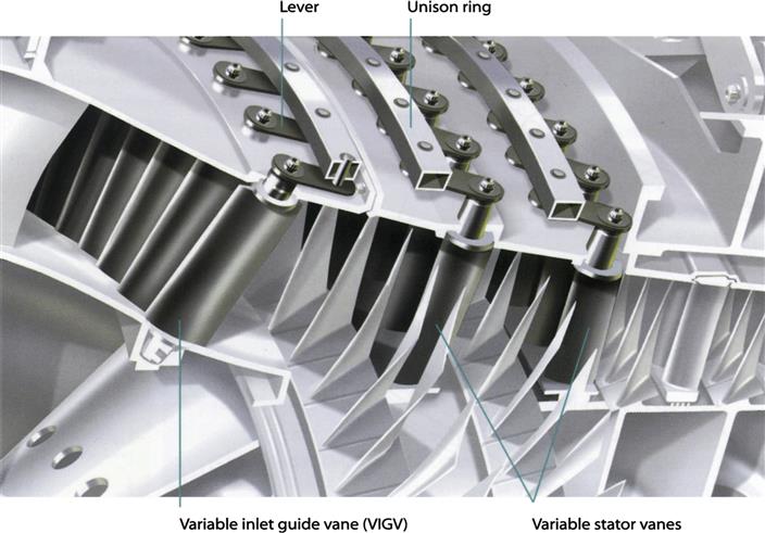
Distortion of inlet airflow is a significant issue for military fans, given the comparatively extreme maneuvers of military aircraft and the often more complex air intake system. Because of the need for a higher pressure ratio, military fans tend to be multi-stage, and may be configured with VIGVs. The splitter on military fans is usually downstream of the fan bypass vanes, or outlet guide vanes (OGVs). (See figures 4–12 and 4–13).
Civil Aero Engine Fans
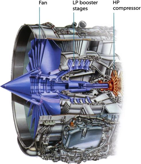
The modern civil aero engine has a very high bypass ratio turbofan configuration. In this configuration, the intake air undergoes only one stage of compression in the fan before being split between the core (or gas generator system) and the bypass stream. For modern engines, the bypass ratio can be as high as ten. This results in the optimum configuration for passenger and transport aircraft flying at just below the speed of sound. For large engines, a three-shaft configuration is preferred, with an intermediate-pressure (IP) compressor and high-pressure (HP) compressor in the core section.
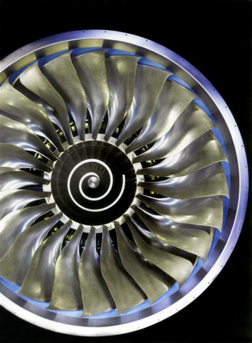
The major components of the civil fan system are the fan blades, fan disc, containment casing, and the FBH structure containing the bypass vanes and engine section stators.
To reduce the fan diameter, and therefore weight and drag, the inlet hub-tip ratio is minimized, subject to meeting mechanical criteria for the hub design. The fan blade comprises an aerofoil with a root attachment that secures the blade into the fan disc. The rotor is attached to the fan shaft, which is connected to and driven by the LP turbine. The whole fan rotor assembly is supported by the FBH. The flow leaving the OGVs is axial. The flow leaving the engine section stators may be axial or swirling, depending on the engine configuration.
Fan Blade
The hollow, wide-chord fan blade allows higher flow, higher efficiency, and is quieter than its predecessor, the snubbered blade. A snubbered blade consists of a solid aerofoil, which has two appendages, or snubbers, attached at right angles to the aerofoil span at about three quarters of the blade height. These are also known as clappers. When the blade is assembled, these snubbers form a support, which resists twisting of the aerofoil when subjected to cyclic loading caused by aerodynamic distortion and wakes. They also raise the natural frequencies of the blade and provide a course of damping. Simply making the blade snubberless results in a design that is too flexible (its natural frequencies are too low) and removes the mechanism for damping any aerofoil vibration. To overcome this, the blade chord is increased, stiffening the blades and allowing a reduction in the number of aerofoils.
One of the principal reasons why civil designs adopted the wide-chord fan is efficiency. Snubbers introduce a significant amount of aerodynamic loss, resulting in a very inefficient design; they also present a blockage to the airflow, requiring the frontal area to be increased. To avoid excessive fan module weight, the aerofoil is hollow; this not only lightens the individual fan blade but also lightens the whole system (disc, front structure, containment casing).
A hollow blade has a cavity within the aerofoil and is formed from three sheets of titanium: two outer sheets and one inner sheet–a very thin membrane. These blades are produced using diffusion bonding and super-plastic forming processes. Hollow blades behave in a very similar manner to solid blades and there is no detriment in stiffness of bird strike capability. The larger the blade, the greater the benefit from hollow blade technology as more weight can be saved. As blades reduce in size they can no longer be hollow because the panels would become too thin. (See figure 4–14 and 4–15).
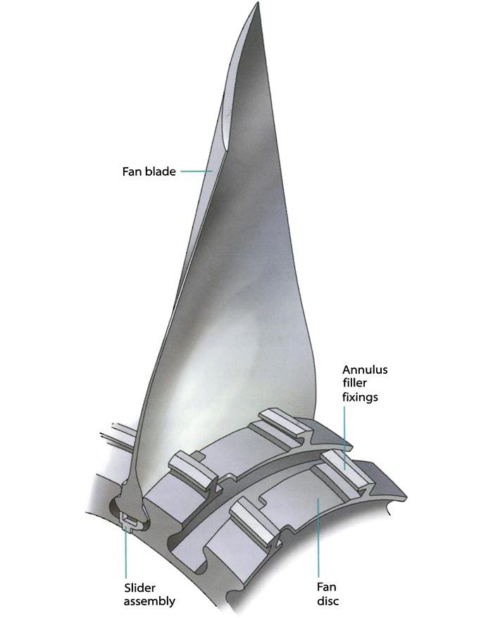
Fan Disc
The fan disc is one of the most critical components in the engine and has four main functions:
• react to centrifugal loads from the fan blades—both during normal running and in the event of a fan-blade-off
• provide attachment from the LP shaft to drive the fan and to retain the fan blades
• provide attachment for the nose cone and other peripheral components
As disc failure is hazardous to the aircraft, this component is classified as a critical part. The disc contains a number of slots into which the fan blades are fitted and there is a front drive arm, which provides attachment to the nose cone assembly. The disc material is usually forged titanium. The mechanical design of the disc is one of the key design areas, because it is a critical part, and it is an extremely heavy component of the fan system. The role of the disc is to ensure that the blades continue to travel in a circular path and resist their high centrifugal loads—about one hundred tons, equivalent to ten double-decker buses hanging from each fan blade.
The total disc stress is a combination of inertia stresses of the disc itself and the stresses imposed by centrifugal force on the blades. Two key issues govern the amount of stress the disc is designed to withstand. First, the burst criteria state that, if the assembly overspeeds, the disc will not burst and compromise the integrity of the engine; this provides the minimum cross-sectional area for the disc. The second major issue is the life of the disc; this sets the maximum stress in the disc. If it is unable to meet the life criteria, then various strategies can be employed:
• increase the size of the disc, so that the stress in the disc reduces to acceptable levels. Any extra material added is put at the bore, the most weight efficient location
• decrease or eliminate any stress concentrations in the disc, such as small holes or tight radii
• increase the capability of the material
• if the material properties exceed the life requirement, then the disc size can be reduced until it reaches the minimum size and weight, as specified by the burst overspeed margin. (See figures 4–16 to 4–18).
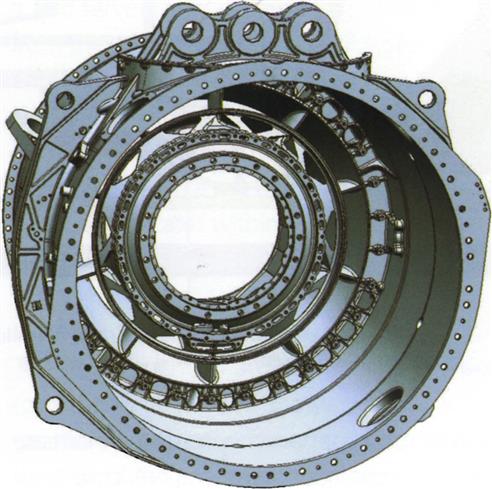
Fan Casing
The primary functions of the fan case are to form the outer gas path, and contain a fan blade should it disintegrate during flight. The casing must be capable of absorbing the energy of a complete fan blade, without releasing blade or case fragments, and maintain the integrity of the engine. The energy of a released fan blade is equivalent to a family saloon car at 100 kmh (60 mph). The casing therefore needs to have high strength and high ductility.
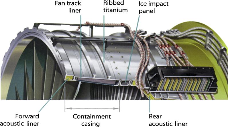
In some engines, the fan case is part of the engine mounting system and thus transmits thrust from the core engine to the aircraft. It interfaces at its front flange with the nacelle and at its rear flange with the rear case (typically military) or with an OGV ring (typically high bypass civil). The fan case also provides mounts for the gearbox, ground support equipment, and other accessories mounted on the accessories flange. The casing assembly also contains acoustic liners to attenuate noise generated by the fan. The panels are made from a honeycomb structure of composite construction. The fan case inner profile, when fully assembled with the in-fill panels, fan track liner, acoustic panels, and ice impact panel, forms the outer annulus line. Containment system weight is a function of the fan diameter cubed so high bypass ratio engines with a large fan blade tip-to-tip diameter have much heavier containment systems.
Military Aero Engine Fans
The major components of the military fan module are the rotor drum, casing and other statics, fan blades, and support structures. Military fans can be configured with either a rear support structure (an overhung rotor), or a front and rear support structure (a “straddle-mounted” rotor). Where a VIGV stage is present, this is incorporated into the front bearing structure.
To minimize the frontal area, and hence weight, drag, and ultimately airframe visibility, the inlet hub-tip ratio is kept as low as possible. The need for low frontal area and low weight means that, in modern military engines, the rotor assembly often has blisks, where the blades and disc are integrated into a single component. The stators are usually of shrouded construction and are mounted into the casing. The flow leaving the OGV is axial. The casing may also have a casing treatment to improve the fan's stall and surge characteristics.
Fan Rotor
The fan rotor configuration has traditionally consisted of two or three discs, each with a set of rotor blades of aerofoil cross-section. The discs and, in more modern engines, blisks, can be bolted or welded together. The blisk is a challenging component to manufacture. There are two very different methods:
• machining from a single, solid piece of metal
• linear friction welding–this allows the engineer both to optimize the properties of the aerofoil and disc, and also to use hollow aerofoil technology so that the blades and disc can be even lighter.
In the fan system, blades, discs, and blisks are usually made of titanium.
Fan Casing and Statics
The military fan casing has various functions:
• form the outer gas path, and provide close control of tip clearance for the rotors
• support the statics (stator vanes), and also the front bearing structure
• provide a mount for the VIGV actuation system where present
The casing needs to have high strength and ductility to achieve these requirements. The inside surface of the casing incorporates an abradable lining material similar to those used in civil casings. The abradable material is axially aligned with the rotor tips and helps to maintain tight tip clearances, which are critical for performance and stability.
The casing is normally split horizontally in two halves, with the vanes secured into the casing via a dovetail fixing. The vanes are shrouded and are fitted with an inner shroud ring to provide integrity. The inside diameter of the shroud ring incorporates abradable material, which provides a sealing face against the rotor labyrinth seal thereby preventing the leakage of air from stator exit to stator inlet.
The casing and vanes can also be of integral construction: the vanes are built up into rings, like cartwheels, and then assembled to form the casing. For part-speed operation, VIGVs and VSVs can be used and casing treatments can also be applied. The most common form of casing treatment is circumferential grooves, but slotted style treatments are also used. (see figure 4–19).