
Vertical Axis Wind Turbines
Farm and Turbine Design
Robert Whittlesey, Exponent, Los Angeles, CA, United States Email: [email protected]
Abstract
Vertical Axis Wind Turbines (VAWTs) represent a unique form of power-generating technology. Historically, they have been relegated to fulfilling a small niche market in commercially available wind turbines due to their “yaw-less” design. Current VAWT designs lag behind their Horizontal Axis Wind Turbine (HAWT) counterparts in terms of efficiency, as measured by their power coefficient. However, new research suggests that these types of wind turbines may be better suited for wind farm installations than previously thought. In this chapter VAWT farm research will be reviewed and discussed. This will then be followed by an overview of different parameters for VAWT design, with an eye toward designs suitable for installation in an optimized wind farm.
Keywords
Vertical axis wind turbine; VAWT; wind farm; optimization; blade design; airfoil design
10.1 Vertical Axis Wind Turbines History
Vertical Axis Wind Turbines (VAWTs) have traditionally been relegated to a niche category in the overall wind turbine market. Historically their advantage has been that they can generate power from wind that comes from any direction, in contrast to a Horizontal Axis Wind Turbine (HAWT), which must yaw to account for changes in wind direction. This advantage comes with an associated disadvantage compared to traditional HAWTs in terms of overall efficiency and power output. Many VAWT-focused start-up companies have been launched with great fanfare only to fail sometime later, as their designs are simply not efficient enough to compete with HAWTs—both on a power coefficient basis and on an economic basis (measured as dollars per kilowatt).
Despite their current place within the commercial market, VAWTs have a prominent place in wind turbine history. Indeed VAWTs were the very first type of wind turbines created, with examples of their construction appearing in ruins that date back to 200 BC in Persia [1]. These original turbines were generally directly linked to a millstone for grinding grain [2]. As a result of their orientation, this was accomplished without the use of gears. Furthermore it appears that the earliest designs relied on sail cloth for their blades rather than a rigid material. HAWTs did not appear until later in the 1300s [1]. Thus despite their current challenges, the persistence of the VAWT concept throughout history might give some hope to future VAWT designers regarding their potential.
The remainder of this chapter is divided into two primary sections: a discussion of VAWT wind farms and then a discussion of the relevant features that should be considered for optimal designs.
10.2 Vertical Axis Wind Farms
Historical understanding of the performance of wind turbines in a wind farm has been derived from extensive experience with HAWTs. It has been shown that as HAWTs are brought closer together in space, they will exhibit diminished performance—that is, for the same upstream wind conditions, they will produce less power [3]. This is primarily due to the wake of the upstream wind turbines adversely affecting lateral and downstream turbines.
With this understanding, wind farm developers are generally seeking ways of ensuring that HAWTs have maximum spacing to ensure optimal performance. Some general rules of thumb for HAWT wind farm design are to have at least 3 rotor diameters of separation between adjacent lateral wind turbines and at least 10 rotor diameters of downstream separation between adjacent wind turbines in the wind direction [3]. Even when these guidelines are followed, HAWTs will experience a deficit in performance when installed in a wind farm, relative to an isolated wind turbine installation.
With VAWTs it is unclear how performance would be affected when placed in a wind farm as the wake is fundamentally different than that of HAWTs. Experience, albeit based on HAWTs, would suggest that performance would decline. This question remained untested for many years, with good reason: if VAWTs are inferior to HAWTs in terms of efficiency, why would any wind farm developer want to fill their land with them? Thus it is not surprising that the current commercial market for VAWTs is several orders of magnitude smaller than HAWTs. However, recent research has shown that VAWTs in wind farms may actually be preferred to VAWTs operating in isolation [4]. Said differently, VAWTs in a wind farm could actually perform better than isolated VAWTs. This is markedly counter to historical experience with HAWT wind farms. This difference also means that the performance of a wind farm using HAWTs is not necessarily advantageous when compared to a farm using VAWTs.
10.2.1 Initial Research on VAWT Farms
The research paper that started this exploration into VAWT farms was published in 2010 [5]. In the paper, the goal was to examine whether bioinspiration could help improve the efficiencies of VAWT wind farms. The research revealed a unique configuration of counter-rotating pairs of VAWTs wherein the neighboring turbines were mutually beneficial. This configuration could generate more power from a given VAWT than the VAWT would in isolation. This is in stark contrast to the results obtained from HAWTs where interference from nearby turbines always results in a detriment to power production. The results, based on relatively simple simulations, were followed by field tests of full-scale VAWTs in the Antelope Valley of Los Angeles County, California, United States [4]. A schematic of the possible counter-rotating configurations are shown in Fig. 10.1.
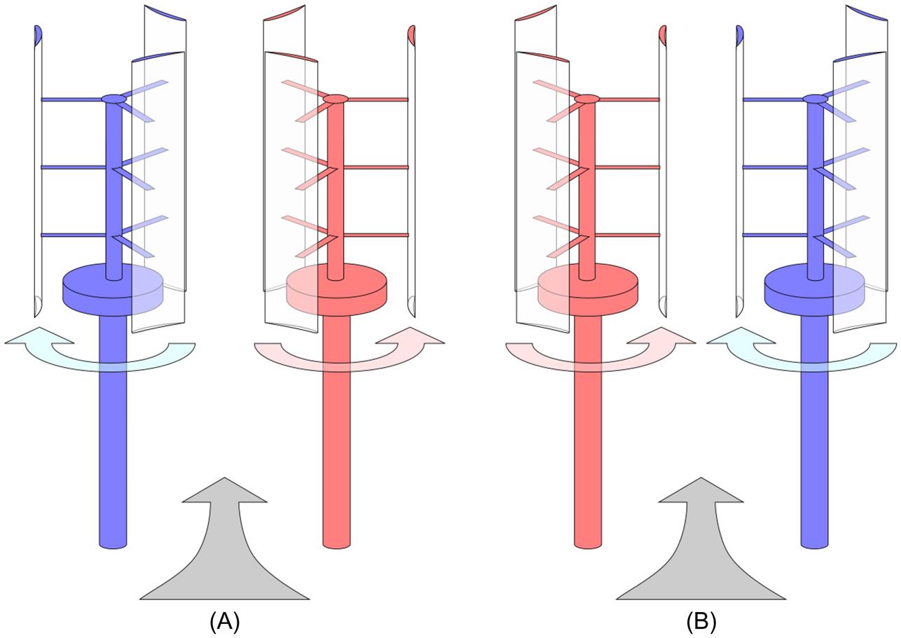
Initial field results showed that, while VAWTs are much less efficient than HAWTs on an individual level, “this deficiency is compensated (indeed, overcompensated) by the fact that VAWTs can be placed closer together” [4]. Furthermore current research suggests that the reverse-doublet is preferred, as depicted in Fig. 10.1B, as turbines in this configuration appear to perform slightly better than turbines in a doublet configuration [6]. However, this result is tenuous, as the uncertainties in the calculations exceed the estimated difference in performance.
10.2.2 Power Density
One metric that was used to examine VAWT wind farms was the power density, which expresses the ratio of the power generated to the area of land used to generate it. The power density for a concentrated power generation facility, such as a coal or a nuclear power plant can be extremely high. However, for distributed generation systems like wind and solar, this metric is crucial to determining the efficiency of a system with respect to the ground it requires. The importance of the metric varies with the location of the generation system. In some areas, a large area of land is both available and has suitable wind for power generation, such as the state of Texas in the United States. However, many island nations that use diesel fuel—a nonrenewable resource—for power generation do so because they have limited land available for power generation by renewables.
More specifically, the island of Grand Cayman has a land area of 200 km2 (76 square miles) [7] and lists a power system that has a capacity of 145.75 MW [8]. This results in a power density of 0.74 W m−2. Thus if one were to cover the entire island with some form of distributed energy production, the goal would be to ensure that the power density of the chosen technology exceeded 0.74 W m−2. Of course, if only one-fourth of the island was available to contribute to power generation, then the power density requirement would increase to 3 W m−2.
For reference, modern HAWT wind farms have a power density of 2–3 W m−2 [4,9]. Thus for the island of Grand Cayman, one would have to cover one-fourth of the entire island with HAWTs (at the closest packing, approximately 3 rotor diameters laterally and 10 diameters downstream). However, Dabiri measured the power density of their VAWT wind farm to be an order of magnitude higher—up to 30 W m−2 [4]. If one chose a more conservative power density, say 10 W m−2, for a VAWT wind farm on Grand Cayman, they would only need to cover 7.4% of the island. This is a substantial reduction in land area compared with the 25% required by a HAWT wind farm. This illustrates the potential value in using VAWTs in a wind farm, as the land area required is minimized.
It should be noted that these values are taken from the full-scale wind farm employed by Dabiri in his research. While the turbines were “full-scale,” they were only 1.2 kW turbines with a total height of 10 m. These are substantially smaller than the modern 1 MW turbines with a total height of 100–150 m.
The reason for the considerable increase in power density is still an area of research. However, the current hypothesis is that the wake downstream of the counter-rotating turbines recovers faster than one would expect [4]. This is based on previous studies of spinning cylinders, which found that vortex shedding and turbulence in the wake are suppressed, provided the rotation rate is high enough [10]. The counter-rotating VAWT is analogous to the spinning cylinders such that, when the tip-speed ratio is high enough, similar effects occur in the downstream wake and thus allow for tighter arrangements of VAWTs in a wind farm than is possible with HAWTs.
Substantial research is continuing to explore this aspect of VAWTs in particular. The reader is recommended to review the results for more details [11,12,13].
10.3 Design Guidelines
In this section, general design guidelines will be explored to give the reader some useful information in designing their own turbine. In the field of VAWTs there are a plethora of differing attitudes and approaches to designing the “ideal” wind turbine. In this section, the design choices will be oriented toward those that could be used most successfully in a counter-rotating wind farm arrangement, such as that discussed previously, as outside of a wind farm HAWTs have a marked advantage. These designs tend to be more “cylindrical” in shape. This is believed to be the most ideal for VAWT wind farms, due to the aforementioned analogy with rotating cylinders. Thus designs like the “Darrieus” wind turbine, which feature arc-shaped blades that connect directly to the rotor shaft, will not be discussed at length in this chapter. Those interested in reading more about the Darrieus-type wind turbine are suggested to consider alternative resources, especially Paraschivoiu’s book [14] and the work done by Sandia [15].
10.3.1 Power Coefficient
The design goal for VAWTs is no different than for HAWTs: to maximize power production. The most general way of expressing the efficiency of the system toward this goal is through the power coefficient, CP, which is defined as:
where P is the power produced by the wind turbine, ρ is the density of the air, U is the freestream velocity, and A is the cross-sectional area of the wind turbine. This is the same equation used in calculating the efficiency of a HAWT, however the cross-sectional area is calculated slightly differently. Rather than using the area of the disk swept by the blades, one generally uses the diameter of the rotors multiplied by the length of the rotor blades, as shown in Fig. 10.2. As with HAWTs, many engineers strive to increase the power coefficient of any design, as this parameter represents the overall efficiency of a wind turbine.

10.3.2 Lift Versus Drag-Based VAWT
Unique to VAWTs there are two aerodynamic mechanisms used to turn the rotor. The “drag” mechanism is so-named as the torque developed by the rotor is principally due to unequal amounts of drag on the blades. One of the most popular drag-based VAWTs is known as the “Savonius” VAWT, in honor of the Finnish engineer Sigurd Johannes Savonius who first patented this style of turbine in 1925 [16]. Fig. 10.3 reproduces some of the figures from his patent. The Savonius VAWT is very robust in that it is simple to design and build; and can indeed produce power. However, it suffers from a substantial design flaw wherein a blade only produces positive torque (positive in the sense that the torque is suitable for producing power) during one half of the blade revolution—when the blade is moving in the same direction as the wind, i.e., “advancing.” When a blade is “retreating,” i.e., moving against the wind, it actually contributes negative torque and thus reduces the net torque applied to the generator. Thus a blade is only producing power during approximately half each revolution. It should be no surprise that this design, while robust and easy to make, is not a serious candidate for substantial power production.

An improvement in power production can be achieved through blades that produce positive torque during the entirety of the blade revolution. This design is known as a “lift” based VAWT. This type of VAWT has blades made of airfoils more-closely-resembling airplane wings. These are also sometimes referred to as “Darrieus-type” VAWTs, in honor of Georges Jean Marie Darrieus, who patented this type of design in the United States in 1926 [17]. Fig. 10.4 shows the figures from Darrieus’ patent filing. Based on the shape of these blades, they generally produce positive torque at every angle when they are operating in their optimal conditions. As a result lift-based VAWTs are generally more efficient than drag-based VAWTs. Most new commercially available VAWTs are based on the concept of aerodynamic lift in order to maximize the power production, but use different airfoil shapes than the “Darrieus” type. An example of a modern lift-based VAWT is shown schematically in Fig. 10.2. This type is also sometimes referred to as a “giromill” or “H-rotor” [18,19].

Despite the inherent power coefficient advantage of lift-based VAWTs, drag-based VAWTs are still being built, primarily by hobbyists who are more interested in learning about wind energy and building turbines themselves than in power production. Their interest is driven by the drag-based VAWT’s simplicity and robustness to design imperfections. The power coefficient in lift-based VAWTs is so much higher than that of traditional drag-based VAWTs that a drag-based design is not normally relevant to any meaningful discussion with respect to wind farms. Thus the rest of this chapter will drop the prefix “lift-based” and simply refer to “VAWT” with the knowledge that we are referring to a lift-based VAWT, unless otherwise specified.
10.3.3 Starting
HAWTs and drag-based VAWTs are able to self-start. By contrast lift-based VAWTs have difficulty starting by themselves. The tip-speed ratio, ![]() , is defined as the ratio of the tangential velocity of the blade tip to the freestream wind velocity. Fig. 10.5 plots the torque produced by the blades of a typical lift-based VAWT in one revolution, represented by the torque coefficient, CQ, as a function of the tip-speed ratio. When the torque is positive the turbine continues to spin and power is produced. However, if the torque coefficient, CQ, is negative, then the turbine eventually stops spinning on its own. The results show that there is a “dead-band” region through which the VAWT must be driven to get to the most efficient power production. Accelerating through this dead-band region requires power—the turbine must be driven by a motor at least to start.
, is defined as the ratio of the tangential velocity of the blade tip to the freestream wind velocity. Fig. 10.5 plots the torque produced by the blades of a typical lift-based VAWT in one revolution, represented by the torque coefficient, CQ, as a function of the tip-speed ratio. When the torque is positive the turbine continues to spin and power is produced. However, if the torque coefficient, CQ, is negative, then the turbine eventually stops spinning on its own. The results show that there is a “dead-band” region through which the VAWT must be driven to get to the most efficient power production. Accelerating through this dead-band region requires power—the turbine must be driven by a motor at least to start.

 . The dead-band region exists for tip-speed ratios between 0.6 and 2.8. Figure adapted from Kirke B. Evaluation of self-starting vertical axis wind turbines for stand-alone applications, Ph.D. Thesis. Griffith University, Queensland, Australia; 1998 [20, p. 15].
The issue of the dead-band region has been addressed previously by electrically powering the turbine until the tip-speed ratio/wind speed was high enough for the turbine to self-spin [15, p. 15]. However, there are electrical and mechanical design challenges inherent in developing a system that turns the rotor in low wind. More recently, the industry has directed itself to developing self-starting designs. One such design involves the use of cambered airfoils (discussed later). However, even some designs with cambered airfoils still feature dead-band regions, which delay or impede self-starting [21].
Additionally, there are few start-up companies that have brought designs to market which attempt to address the self-starting issue through a hybrid turbine—by adding a smaller-radius drag-based VAWT to the shaft of a lift-based VAWT. While these designs have not been studied in depth, it is not expected that their power efficiency will be competitive.
10.3.4 Blade Airfoil Choice
By and large, the modern development of HAWT blades has been greatly aided by the many years of development of airplane airfoils for wings and propellers. More recently, the optimization of airfoils for HAWTs has become specific to the needs of wind turbines. VAWT blades have not been able to take advantage of the same research as the VAWT blades do not exist in the same environment as either wings or propellers. While there are many airfoils from which to choose as a basis for a VAWT blade, the aerodynamics of a VAWT are much more dynamic than a HAWT and require substantially more refinement to maximize performance. In particular, a VAWT experiences flow with a wide range of angle of attack during each rotation.
With this in mind, however, the choice of an airfoil is of paramount importance as “the power produced by a [VAWT] at different wind speeds [is] largely determined by its blade airfoil” (22, p. 494). One can use published literature as a starting point for airfoil design, but a final design would benefit greatly from additional research and development tailored to that specific design’s operating conditions. This will ensure the highest level of performance.
Based on the work done at Sandia National Laboratory [1, p. 17], most of the early studies of airfoils for VAWTs were using symmetric airfoils such as the NACA 00-series. Symmetric airfoils were used in the Sandia 34 m VAWTs that were used in the 1970s through 1990s. These airfoils can produce power; however, they suffer from the self-starting problem mentioned previously.
More recent research has considered cambered airfoils for VAWTs. A cambered airfoil, while increasing the drag a bit, has the potential to allow for self-starting of the VAWT in an entirely passive way [20, p. 319]. In the PhD thesis of Kirke, he writes: “Cambered fixed pitch blades appear to offer the best combination of acceptable starting torque and peak performance with simplicity and low cost” [20, p. 319].
For a given VAWT, the airfoil will have to be specifically tailored to ensure optimal performance. However, good starting points can be found in existing literature. Many have considered the Selig S1210 airfoil as a design basis. The Selig S1210 is intended to be a high-lift, low Reynolds number airfoil. In particular, Kirke studied the Selig S1210 but added “[it] is likely that a profile with even better characteristics [than the S1210] for VAWTs could be designed” [20, p. 320]. In other research, the Selig S1210 airfoil profile was studied and its ability to self-start was confirmed [23]. The blade profile of the Selig S1210 is shown in Fig. 10.6.
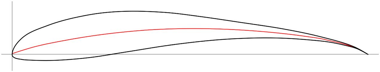
Thus the Selig S1210 may be an appropriate airfoil with which to start a new design since it is able to self-start, a rare feature among historical VAWTs.
Newer research thrusts in the realm of VAWT airfoils, however, have been focused on developing airfoils specifically for VAWTs. Claessens, for instance, has endeavored to improve the performance and self-starting characteristics as compared to the symmetric NACA airfoils and was able to find a number of improvements [24]. This work resulted in the “DU 06-W-200” airfoil, which is shown in Fig. 10.7. As an example of the success of this profile, it was reported to have been used in the commercially produced Windspire VAWT [21, p. 3], a turbine that self-starts. Interestingly, although the DU 06-W-200 airfoil is able to self-start, its degree of camber is far less than the heavily cambered S1210. We also do not yet have any direct comparisons of it to the Selig S1210 airfoil with respect to power production. The current state of research does not offer an explanation or verified model for prediction of power production or self-starting ability.

Thus it is hard to give accurate advice as to which blade profile (Selig S1210, Delft DU 06-W-200, or some other) is superior for wind farm use. Since both have been shown in the literature to offer good results, it seems reasonable to consider the merits intrinsic to each design. There may be compelling aspects of one’s design that suggest one blade design is a more appropriate starting point over the other. Some aspects to consider include the thickness of the blades with respect to structural stiffness (thicker blades being stiffer), ease of construction (e.g., the sharp trailing edge of the Selig S1210 may prove difficult to manufacture), weight (thinner blades being lighter), etc.
10.3.4.1 Blade Refinement
Having chosen a starting blade profile, one must further refine the airfoil design. Although the ultimate test is in the field with experiments, commercial development of a turbine will undoubtedly begin with simulations as the precursor to construction of prototypes and experiments, as minute changes to the airfoil geometry are far faster to execute with a computer than with a full-scale turbine.
In terms of simulations, VAWTs have extremely complex wake profiles that can easily make a simulation (such as one generated using a commercial software package such as FLUENT or Star-CCM) very time-consuming, computationally intensive to run, and subject to significant inaccuracies. As such, it may be beneficial to start with lower-fidelity simulations for exploration of overall concepts and to more quickly generate alterations to the airfoil design.
An appropriate means is to first develop and refine with the “cruder” tools and then move up. A likely testing progression would be to first select an airfoil profile with a simplified 2D analysis (e.g., RFOIL+VAWT performance simulation), refine it using a higher-fidelity Computational Fluid Dynamics (CFD) code (e.g., 3D simulations in Star-CCM, FLUENT, or OpenFOAM), and then lastly test the airfoil profile in a prototype turbine.
As an example, for the simplified 2D analysis, Claessons developed a unique method of simulating the airfoil performance by first running the airfoil profile through RFOIL and then using the results of the 2D airfoil profile to generate the VAWT performance using another software tool [25]. This method is undoubtedly faster than running a very high fidelity CFD simulation in 3D and would allow engineers to more quickly test a wide range of blade profiles and converge on a more optimal solution. For a more detailed discussion on the topic of VAWT modeling, see Paraschivoiu’s book [14].
10.3.4.2 Blade Orientation
For a symmetric blade, there is no issue of blade orientation. However, once a blade is cambered and becomes asymmetric the question arises: how does one install the blade? Is power production better with the camber toward or away from the axis of rotation? It is appropriate to note that the orientation of the blades does matter.
In his PhD thesis, Kirke suggests that the concave side of a cambered airfoil should face outward for optimal VAWT performance [20, p. 48 and p. 165]. This orientation is depicted in Fig. 10.2. This conclusion has been reached independently by others, including the author and some VAWT manufacturers, however, Kirke appears to be the first to have documented this observation.
The idea behind this is that, when installed in this configuration, the blade camber enables the airfoil to perform better during the upwind portion of the rotation cycle and worse during the downwind portion. The vast majority of the power, 90%–95% according to Baker [26, p. 374], is generated during the upwind part of rotation. Thus in order to optimize power production, the camber orientation shown in Fig. 10.2 is best, where the concave side of the camber line faces outwardly. The increase in power production due to the camber on the upwind portion more than offsets the decrease during the downwind portion. If installed in the reverse, the blade, when oriented to produce the most energy, is actually in the downstream wake of other blades on the rotor. The increase in power production during the downwind portion is more than offset by the decrease in power production during the upwind portion.
10.3.5 Blade-Tip Vortices
Based on the canonical wind turbine shown in Fig. 10.2, a blade with straight ends at the top and bottom, as shown, will generate “blade-tip vortices” during each rotation of the rotor, much like an aircraft produces “wingtip vortices.” These vortices are known to be detrimental to performance by increasing the induced drag and, in a wind turbine, would decrease the power production.
One parameter that affects the strength of these vortices is the aspect ratio of the blades. The aspect ratio is defined as the length of the blade relative to its chord. In general it has been found that higher aspect ratio blades result in better performance, just as with aircraft wings, due to the reduction in reduced drag from tip vortices. As an example of this, Kirke’s prototype machine, with an aspect ratio of 7.5, performed much worse than his predictions, which were based on infinite-length blades. He concluded that the low aspect ratio of the blades was to blame. Subsequently he recommended blades with aspect ratios much higher than 7.5 [20, p. 320]. However, the likely reason for Kirke’s results was the production of blade-tip vortices, which were apparent in his aspect-ratio-of-7.5 design and are neglected in his infinite-length-blade-based predictions. VAWTs like that pictured in Fig. 10.2, in particular, have the effects of blade-tip vortices doubled compared to their HAWT brethren because the VAWT would generate blade-tip vortices from the tops and bottoms of the blades whereas a HAWT only has a single blade-tip vortex generated by each blade.
Thus increasing the aspect ratio of the blades by either elongating the blades or reducing the chord of the blades is one method of reducing the strength of the blade-tip vortices. Other means of reducing the blade-tip vortices can be found by the installation of winglets or an endplate/fence at the blade tip. Amato et al. conducted numerical simulations of various blade-tip devices to determine their effect on power coefficient [27]. Their study found that nearly all tip treatments resulted in power production improvements, however, a carefully designed winglet resulted in the highest power coefficient increase of approximately 7%. This is a marked improvement in power production for a passive device.
10.3.6 Blade Reynolds Number
The Reynolds number is a commonly used nondimensional parameter in fluid mechanics, which describes the ratio of inertial forces to viscous forces. In the context of VAWTs, the Reynolds number is defined using the kinematic viscosity of the air, the freestream velocity of the wind, and the chord length of the blade as follows:
where c is the chord length, ![]() is the freestream velocity of the wind, and
is the freestream velocity of the wind, and ![]() is the kinematic viscosity. Using this definition of the Reynolds number, Kirke suggests that low Reynolds numbers contribute to difficulty in the self-starting of a VAWT. Hence larger Reynolds numbers are desired. Additional research in this area by Brusca et al. found a similar result: increasing the Reynolds number increased the power coefficient of a given VAWT [18].
is the kinematic viscosity. Using this definition of the Reynolds number, Kirke suggests that low Reynolds numbers contribute to difficulty in the self-starting of a VAWT. Hence larger Reynolds numbers are desired. Additional research in this area by Brusca et al. found a similar result: increasing the Reynolds number increased the power coefficient of a given VAWT [18].
In practice, this advice is synonymous with ensuring that (1) the wind velocity magnitude is high and (2) the blade chord, which is proportional to the blade area, is large. However, it is not clear if the fault is in the wind velocity or if there is actually a Reynolds number dependence on performance (e.g., transition to turbulence or drag buckets). This should also be considered in more detail.
10.3.7 Turbine Mass
In general the turbine rotor mass is of particular concern as a design driver. The rotor mass is defined as all of the components which rotate: principally, the rotor shaft, the struts, and the blades. As the turbine rotor becomes more massive, all connecting systems must be upgraded, including the rotor shaft, the tower, and the foundation. Thus a lighter turbine mass is generally desired. Furthermore the lighter the blades and rotor are, the smaller the rotational moment of inertia of the VAWT rotor. This, in turn, allows the turbine to spin up and subsequently respond to wind gusts more quickly. Both of these features will then lead to greater power production and a higher capacity factor for the wind turbine.
The primary concern for a lighter turbine is one of structural or dynamic loads. Heavier, more massive blades are generally stronger and dampen vibrations better. Thus a trade-off must be made between a turbine that will ensure a safe, long operation, and one that is lighter and more responsive.
10.3.8 Turbine Diameter
For VAWTs, the turbine diameter as defined in Fig. 10.2, is a unique parameter that does not have a direct analog in the HAWT world. In the literature there are currently no design guidelines to follow. However, the turbine diameter has an effect on aspects of the wind turbine performance. In particular, the larger the turbine diameter, the longer the blade struts must be to support the blades. Thus a larger diameter turbine is more massive and has a direct effect on the turbine inertia, as discussed earlier. Furthermore a larger turbine diameter results in a slower angular velocity, assuming the same tip-speed ratio. A slower angular velocity then may require that a gearbox be included in the design to ensure the angular velocity of the generator is sufficiently high for efficient power production.
Of course, the trade-off is that a smaller turbine diameter leads to higher centripetal forces on the rotor blades, at the same tip-speed ratio, as the centripetal force is proportional to 1/r. Higher angular velocities also increase the propensity for fatigue failure of the blade struts due to more frequent cyclic loading. This is a special concern for VAWTs of this design, since the energy released in a blade liberation event is significant. An example of some VAWT failures due to blade liberation is available in Dabiri et al. [28].
10.3.9 Number of Blades
The concerns surrounding the number of blades in a VAWT are very similar to those surrounding the number of blades in a HAWT. Designs featuring fewer blades generate more “ripples” in the power output, whereas extremely high numbers of blades result in decreased power production due to drag. The lowest number of blades in a design has principally been 2 blades, as seen in the original Sandia turbines. However, many later embodiments have used 3 blades. There are commercial designs on the market featuring 4- and 5-bladed designs, such as those made by State of the Art Wind Technologies (SAWT).
The advantage of the increased blade numbers are increased rotor stability and a reduction in the “torque ripple” experienced by the 2-bladed design, particularly during low rotation rates [15, p. 38]. This results in a smoother power output. To expand upon this, Sutherland et al., while reflecting on the Sandia VAWT development, writes: “…the use of 3 blades appears to be optimal … adding more blades appears to add significant costs without reducing balance-of-system costs” [15, p. 38]. Furthermore Kirke and Lazauskas suggest “using at least 3 blades rather than 2” with respect to vibration [29, p. 4]. Three blades have been featured in many other designs and studies [20,30]. A study comparing 3- and 6-bladed designs numerically, found that the power coefficient was higher for a 3-bladed design [31].
10.3.10 Struts
Struts are used to hold the blades to the main rotor shaft as shown in Fig. 10.2. They need to be strong in order to resist the aerodynamic, gravitational, and centripetal forces exerted on the blades. However, they generally impede power production and decrease the power coefficient through their increased drag. Since drag scales with velocity to the second power and the linear velocity of a strut scales linearly with its radial position from the rotor shaft, most of the drag effect is concentrated at the connection to the blade. There are some advantages in choosing an aerodynamically “smooth” strut design or in covering the strut with a low-drag fairing, and the use of symmetric airfoil sections for fairing the struts is recommended [20, p. 212] [30]. In one demonstration turbine, the addition of aerodynamic fairings to round pipe struts resulted in a 15% increase in measured performance [15, p. 36].
The number and location of the struts is both a structural concern and an aerodynamic one. It is recommended to minimize the number of struts concomitantly with good structural design, as each strut removed eliminates some parasitic drag on the rotor and ultimately results in a higher power production.
10.4 Summary
In conclusion the following points have been made regarding the design of VAWTs and how to aggregate VAWTs in wind farms:
• Counter-rotating VAWTs have been found to have substantially increased power density (W m−2) over conventional HAWT wind farms
• VAWTs should be designed to use lift rather than drag as the basis of operation
• VAWTs can have difficulty self-starting, but careful airfoil selection and cambered airfoil profiles can alleviate these difficulties
• The Selig S1210 and DU 06-W-200 airfoil profiles have been shown to self-start and form a currently acceptable starting point for new blade airfoil designs
• Struts should be shaped to reduce aerodynamic drag
• Lower turbine rotor mass, larger aspect ratio blades (e.g., long “slender” blades), blade-tip devices (e.g., winglets), and 3-bladed rotor designs are preferred.
The VAWT field is relatively nascent compared to HAWTs. As more research is completed and published, some of the design guidance herein may be superseded as the technology improves. The reader is advised to always consider any new research that becomes available.