
Wind Turbine Technologies
Anca D. Hansen, Technical University of Denmark, Roskilde, Denmark Email: [email protected]
Abstract
This chapter provides an overview of the most relevant configurations and characteristics of various contemporary wind turbine technologies, including their advantages and disadvantages. A short introduction to the main wind turbine components (i.e., aerodynamic rotor, transmission system, generator, power electronic interface, control system) is provided as well.
Keywords
wind turbine components; aerodynamic rotor; wind turbine transmission system; wind turbine generator; wind turbine power electronic interface; wind turbine control system; wind turbine technology
8.1 Introduction
The wind turbine technology is a very complex technology involving multidisciplinary and broad technical disciplines such as aerodynamics, mechanics, structure dynamics, meteorology as well as electrical engineering addressing the generation, transmission, and integration of wind turbines into the power system.
Wind turbine technology has matured over the years and become the most promising and reliable renewable energy technology today. It has moved very fast, since the early 1980s, from wind turbines of a few kilowatts to today’s multimegawatt-sized wind turbines [1–3]. Besides their size, the design of wind turbines has changed from being convention driven to being optimized driven within the operating regime and market environment. Wind turbine designs have progressed from fixed speed, passive controlled and with drive trains with gearboxes, to become variable speed, active controlled, and with or without gearboxes, using the latest in power electronics, aerodynamics, and mechanical drive train designs [4]. The main differences between all wind turbine concepts developed over the years, concern their electrical design and control.
Today, the wind turbines on the market mix and match a variety of innovative concepts, with proven technology for both generators and power electronics [4]. The continuously increased and concentrated electrical penetration of large wind turbines into electrical power systems inspires the designers to develop both custom generators and power electronics [5,6] and to implement modern control system strategies.
8.2 Overview of Wind Turbine Components
A wind turbine consists of a tower and a nacelle that is mounted on the top of a tower. The nacelle contains several components, which contribute with their specific function in the energy conversion process from wind energy into electrical energy. Fig. 8.1 shows the main components of a wind turbine including the turbine rotor, transmission system (gearbox), generator, possible power electronics, control system, transformer, and finally its connection to the grid.

8.2.1 Aerodynamic Rotor
The aerodynamic rotor of a wind turbine captures the power from the wind and converts it to kinetic mechanical power. The aerodynamic rotor is mainly made up of a hub and blades, with the latter attached to the hub by mechanical joints. Modern wind turbines have typically two or three blades, made up by a matrix of fiber glass mats impregnated with polyester [8]. In the old wind turbines the blades can be firmly attached to the hub, while in the more modern ones the blades can be turned around their longitudinal axes.
8.2.2 Transmission System
As depicted in Fig. 8.1, the kinetic mechanical power from the aerodynamic rotor is transmitted to the generator through a transmission system, which typically consists of the rotor shaft, mechanical brake(s), and a gearbox.
The mechanical brakes are usually used as a backup system for the aerodynamic braking system of the wind turbine and/or as a parking brake once the turbine is stopped. The aerodynamic brake system usually consists of turning the blade out of the wind, namely 90 degrees about the longitudinal axis of the blade.
The main purpose of the gearbox is to act as a rotational speed increaser; the gearbox of a wind turbine converts the slow high torque rotation of the aerodynamic rotor into the much faster rotation of the generator shaft. Depending on their geometrical designs, gearboxes are typically divided in two classes. The first one is the spur and helical gearboxes, which consists of a pair of gear wheels with parallel axes. The second one is the planetary gearbox which consists of epicyclic trains of gear wheels [9]. As the gearbox is continuously subjected to large and varying torques due to increased size of wind turbines and wind speed variability, the gearbox is the weakest link in the wind turbines, many of them failing in less than 2 years of operation [9]. As a result, in some of the newer wind turbines technologies, the gearbox has been removed, by designing generators, with a multipolar structure in order to adapt the rotor speed to the generator speed. The generator speed decreases by increasing number of pole pairs, and therefore the gearbox may not be necessary for multipole wind turbine generator systems, i.e., where number of pole pairs may be higher than 100.
8.2.3 Generator
The generator is an electromechanical component, which converts the mechanical power into electrical power. As indicated in Fig. 8.2, generators have typically a stator and a rotor. The stator is a stationary housing, which has coils of wire mounted in a certain pattern. The rotor is the rotating part of the generator and is responsible for the magnetic field of the generator.

A rotor can have a permanent magnet or an electromagnet, namely a magnetic field is generated on the rotor and rotates with the rotor. By its rotation, the rotor and thus its magnetic field pass the stator windings and induce a voltage in the terminals of the stator. When the magnetic field of the stator is following the magnetic field of the rotor, the generator is called synchronous, otherwise it is called asynchronous.
Two major types of generators used in the industry are: synchronous generator (SG) and asynchronous (induction) generator. Descriptions of synchronous and asynchronous generators can be found in many standard textbooks. For example, Refs. [4,13,14] provide a good overview regarding the different generator technologies currently used by the wind industry as well as future options for the design of wind turbine generators.
8.2.3.1 Synchronous Generator
The SG is a generator, which operates at the synchronous speed, dictated by the frequency of the connected grid, regardless of the magnitude of the applied torque. The magnetic field in the SG can be created by using permanent magnets or with a conventional field winding.
The speed of the SG is determined by the frequency of the rotating field and by the number of pole pairs of the rotor. If the SG has a suitable large number of poles (i.e., multipole structure) it can be used for direct-drive applications without the need of a gearbox.
The SG is more expensive and mechanically more complicated than an asynchronous generator of a similar size. However, it has one significant advantage compared with the asynchronous generator, namely, that it does not need reactive magnetizing current and thus no further power compensation equipment.
Two classical types of SGs are often used in the wind turbine industry:
• Wound rotor synchronous generator (WRSG) is the workhorse of the electrical power industry and therefore very well documented in the literature [13–15]. Its stator windings are connected directly to the grid and hence the rotational speed is strictly fixed by the frequency of the supply grid. The rotor winding, through which direct current (DC) flows, generates the exciter field, which rotates with synchronous speed.
• Permanent magnet synchronous generator (PMSG) has a wound stator, while its rotor is provided with a permanent magnet pole system. It has a high efficiency as its excitation is provided without any energy supply. However the materials used for producing permanent magnets are expensive and they are difficult to manufacture. Additionally, the use of permanent magnets excitation requires the use of a full-scale power converter in order to adjust the voltage and frequency of generation to the voltage and the frequency of transmission, respectively. Different topologies of PMSG are presented in the literature [16–18]. The most common types are the radial flux machine, the axial flux machine, and the transversal flux machine.
8.2.3.2 Asynchronous (Induction) Generator
The asynchronous generator has several advantages such as robustness, mechanical simplicity and as it is produced in large series, it also has a low price. The major disadvantage is that the stator needs a reactive magnetizing current. As the asynchronous generator does not contain permanent magnets and is not separately excited, it consumes reactive power in order to get its excitation. The reactive power may be supplied by the grid or by power electronics.
In the asynchronous generator, an electric field is induced between the rotor and the rotating stator field by a relative motion called slip, which causes a current in the rotor windings. The interaction of the associated magnetic field of the rotor with the stator field results in a torque acting on the rotor.
The rotor of an asynchronous generator can be designed as a short-circuit rotor (squirrel-cage rotor) or as a wound rotor [13]:
• Squirrel-cage induction generator (SCIG)—has been often used by the industry over the years, due its mechanical simplicity, high efficiency, and low maintenance requirements. As depicted in Fig. 8.3, the rotor of this generator has conducting bars embedded in slots and shorted in both ends by end rings. The electrical characteristics of the rotor can therefore not be controlled from the outside.
SCIG is very robust and stable generator, its speed changing by only a few percent as its slip varies with the changes in the wind speed. Wind turbines based on SCIG are typically equipped with a soft-starter mechanism and an installation for reactive power compensation, as SCIGs consume reactive power. SCIGs have a steep torque speed characteristic and therefore fluctuations in wind power are transmitted directly to the grid. These transients are especially critical during the grid connection of the wind turbine, where the inrush current can be up to seven to eight times the rated current.
In a weak grid, this high inrush current can cause severe voltage disturbances [25]. Through the soft starter, the generator is gradually connected to the grid in order to limit the inrush currents. The amount of reactive power for the generator varies depending on the wind conditions. This means that if the wind speed is high, the wind turbine can produce more active power, but only if the generator gets more reactive power. Without any electrical components to supply reactive power, the needed reactive power for the generator is taken directly from the grid and this might cause additional transmission losses and can, in some situations, make the grid unstable. To avoid this, capacitor banks or modern power electronic converters are typically used to provide the needed reactive power compensation.
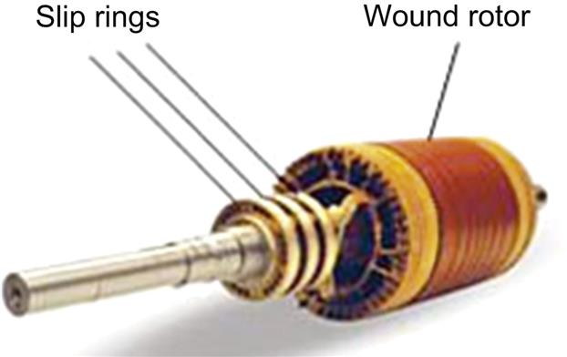
• Wound rotor induction generator (WRIG)—the windings of the wound rotor can be externally connected through slip rings and brushes or by means of power electronic equipment (Fig. 8.4). This means that this generator has the advantage that its electrical characteristics can be controlled from the outside, and thereby a rotor voltage can be impressed.
By using power electronics, the power can be extracted or impressed to the rotor circuit and the generator can be thus magnetized from either the stator circuit or the rotor circuit. The disadvantage of WRIG is that it is more expensive than and not as simple and robust as the SCIG. Two WRIG configurations are mainly used in the wind industry:
• OptiSlip or FlexiSlip induction generators were often used in 1990s, as WRIGs with a variable external rotor resistance attached to the rotor windings, which can be changed by an optically controlled converter mounted on the rotor shaft, and hence the name. This optical coupling eliminates the need for costly slip rings that need brushes and maintenance. The range of the dynamic speed control depends on the size of the variable rotor resistance. Typically, the slip for OptiSlip is 10%, while for FlexiSlip it is about 16% [4].
• Doubly fed induction generator (DFIG)—has the stator windings directly connected to the constant frequency grid, while the rotor is connected to the grid through a back-to-back power converter. The size of this converter is related to the selected speed range, namely it is not a full-scale power converter, since typically only a fraction up to 70% of the speed range is utilized. The selection of the speed range is based on the economic optimization of investment costs and on increased efficiency. Thus the cost of the converter increases when the speed range around the synchronous speed becomes wider. DFIG has the ability to control independently its active and reactive power. A drawback of the DFIG is the inevitable need for slip rings [15,21].

8.2.4 Power Electronic Interface
The generator converts the mechanical power into electrical power, which is fed into the power grid through a power electronic interface [5,24]. As it is placed between the wind turbine generator and power grid, the power electronic interface should satisfy both generator and grid side requirements with a cost effective and easy maintenance solution. On the generator side, this interface ensures that the rotating speed of the turbine is continuously adjusted in order to extract maximum power out of the wind [17–19] following a maximum tracking point. On the grid side, the power electronic interface must comply with the grid codes [22] regardless of the wind speed, such as ability to control active and reactive power, frequency and voltage control.
The penetration of power electronics in wind turbine systems has been continuously growing since the 1980s, becoming gradually more and more advanced and bringing in significant performance improvements for the wind turbines—not only reducing the mechanical stress/loading and increasing the energy yield, but also enabling wind turbines to behave as active controllable components in the power system and support the grid similarly to the conventional power plants [21]. Nowadays, components can handle higher current and voltage ratings, the power losses decrease and the devices become more reliable.
The most commonly used power electronic interfaces in wind turbine applications over the years are:
• Soft starter is a simple and cheap power electrical component used in 1980s in wind turbines with SCIG to reduce the inrush current during wind turbines connections to the grid, thereby limiting the disturbances to the grid. Without a soft starter, the inrush current can be up to seven to eight times the rated current, which can cause severe voltage disturbances on the grid [24].
• Capacitor bank is an electrical component that supplies reactive power to the asynchronous generators of wind turbines [24]. Traditionally, mechanically switched capacitor banks are the easiest and most economical way to minimize the reactive power drawn by asynchronous generators from the grid. The generators of wind turbines can have a full load dynamic compensation, where a certain number of capacitors are connected or disconnected continuously, depending on the average reactive power demand of the generator over a predefined period of time. As the reactive power demand of an asynchronous generator is strongly dependent on wind speed, the capacitor banks can often be triggered by an extreme number of switching events.
• Frequency converter, typically used in wind turbines since 2000, is a device which facilitates interconnection of two electrical systems with independent frequencies [24]. It makes it possible to adjust and control the generator frequency and voltage, and thus enhance wind turbines capability to behave and act as active components in the power system. A traditional frequency converter, also called an adjustable speed drive, consists of:
• Alternating current (AC)/direct current (DC) conversion unit (rectifier) converts AC into DC, while the energy flows into the DC system;
• Capacitors (energy storage);
• DC/AC conversion unit (inverter) converts DC into AC, while the energy flows to the AC system.
During recent years different converter topologies (back-to-back/multilevel/tandem/matrix/resonant converters) have been investigated to test whether or not they can be used in wind turbines. The back-to-back converter is highly relevant to wind turbines today. It constitutes the state of the art and may therefore be used for benchmarking the other converter topologies. As discussed in Ref. [23], the matrix and multilevel converter are the most serious competitors to the back-to-back converter and thus are recommended for further studies.
8.2.5 Control System and Wind Turbine Control Capabilities
A wind turbine is typically equipped with a control system, necessary to assure a proper operation of the wind turbine under all operational conditions. The control system is meant to control and keep the wind turbine within its normal operating range by passive or active means. Passive controls use their own sensing and are exercised by use of natural forces, e.g., when the rotor “automatically” loses the aerodynamic efficiency (known as stall phenomena), when the wind speed exceeds a certain critical level. Active controls use electrical, mechanical, hydraulic, or pneumatic means and require transducers to sense the variables that will determine the control action needed. Typical variables which are monitored in a control system are wind speed, rotor speed, active and reactive power, voltage and frequency of the wind turbine’s point of connection. In addition, the control system must be able to stop the wind turbine, if necessary.
The overall goal of wind turbine active control is to maximize the power production and to reduce the structural loads on the mechanical components and thus their costs and life time consumption. At low wind speeds the control system has to ensure that the turbine produces optimal power, namely that the wind turbine is extracting power out of the wind with maximum efficiency. At high wind speeds, namely higher than the rated wind speed, the power production of the turbine should be limited to the rated power value and thereby reduce the driving forces on the blades as well as the load on the whole wind turbine structure.
All wind turbines are designed with some sort of power control [4]. Three options for the power output control are currently used: stall control, pitch control, and active stall control. The main differences between these options concern the way in which the aerodynamic efficiency of the rotor is limited during above the rated wind speed in order to prevent overloading.
• Stall control (passive control) is the simplest, most robust and cheapest power control method. Here the blades are firmly attached to the hub and the wind attack angle of the wings is fixed. The design of rotor aerodynamic causes the rotor to stall “automatically” (so losing efficiency) when the wind speed exceeds a certain level, i.e., rated value.
• Pitch control (active control) means that the blades can be quickly turned away from or into the wind as the power output becomes too high or too low, respectively. In contrast to stall control, pitch control requires that the rotor geometry changes and it is therefore more expensive due to its pitching mechanism and controller. The pitching system can be based on a hydraulic system, controlled by a computer system or an electronically controlled electric motor. The pitch control system must be able to adjust the pitch angle by a fraction of a degree at a time, corresponding to a change in the wind speed, in order to maintain a constant power output.
• Active stall control, as the name indicates, means that the stall of the blade is actively controlled by pitching the blades in the opposite direction than a pitch-controlled wind turbine does. This movement increases the angle of attack of the rotor blades in order to make the blades go into a deeper stall and into a larger angle of attack. In contrast to stall control, the active stall control has the advantage of being able to compensate for variations in the air density.
The wind turbines can also be classified according to their speed control ability into two significant classes such as fixed-speed wind turbines and variable-speed wind turbines.
• Fixed-speed wind turbines were the most common installed wind turbines in the early 1990s. Characteristic for these wind turbines is that they are equipped with a SCIG connected directly to the grid, a soft starter, and a capacitor bank for reduction of reactive power consumption. Regardless of the wind speed, the rotor speed of the wind turbine is almost fixed, stuck to the grid frequency and cannot be changed. Fixed-speed wind turbines are designed to achieve maximum efficiency at one particular wind speed, namely at the most likely wind speed in the area where the wind turbine is placed. Fixed-speed wind turbines have the advantages of being simple, robust and reliable, well proven and with low cost of electrical parts. Its direct drawbacks are high mechanical stress, uncontrollable reactive power consumption, and limited power quality control [25].
• Variable-speed wind turbines have become the dominant type among the installed wind turbines during the past decade. Variable-speed operation can only be achieved by decoupling the electrical grid frequency and mechanical rotor frequency through a power electronic interface. Characteristic for these wind turbines is that they are designed to achieve maximum aerodynamic efficiency over a wide range of wind speeds. Within variable-speed operation, it is possible to continuously adapt (accelerate or decelerate) the rotational speed of the wind turbine to the wind speed, in such a way that the turbine operates continuously at its highest level of aerodynamic efficiency. The advantages of variable-speed wind turbines are an increased annual energy capture (this is about 5% more than the fixed-speed technology) and that the active and reactive power can be easily controlled [17–18]. They have also less mechanical stress, improved power quality and, not least, controllability and “grid friendliness,” which is a prime concern for the grid integration of large wind farms. The disadvantages are the additional losses due to power electronics that increase the component count and make the control system more complex. Beside these, they have also an increased cost due to the power electronics, which is about 7% of the whole wind turbine [17–19,26].
Fixed-speed wind turbines have been used with all three types of power control options by the industry. Until the mid-1990s, when the size of wind turbines reached the megawatt range, the stall control fixed-speed wind turbines, were the predominant type.
Pitch control applied to fixed-speed wind turbines has not been very attractive due to the large inherent power fluctuations at high wind speeds; the pitch mechanism is no fast enough to avoid power fluctuations in case of gusts at high wind speeds.
Active stall fixed-speed wind turbines have been popular in 1990s, due to their smooth limitation in power. However, as they have a very slow control, their success is strongly conditioned by their ability to comply with the stringent requirements impose these days by the utility companies.
The pitch control method has proved to be a very attractive option for variable-speed operation and for larger wind turbines than 1 MW. The variable-speed wind turbines are today only used in practice together with a fast pitch mechanism, due to power limitation considerations [4]. The reason why variable-speed stall or variable-speed active stall control wind turbines are not considered is their lack of ability for rapid reduction of power. If such variable active stall controlled wind turbine is running at maximum speed and encounters a large wind gust, the aerodynamic torque can become critically large and may result in a run-away situation.
8.3 Contemporary Wind Turbine Technologies
This section presents an overview of the contemporary wind turbine technologies with their configurations, characteristics, advantages, and drawbacks. Depending on the generator type, power electronics, power and speed controllability, the wind turbines can generally be categorized into four categories.
8.3.1 Fixed-Speed Wind Turbines (Type 1)
The fixed-speed wind turbine configuration uses a multiple-stage gearbox and a SCIG to convert the mechanical energy from the wind into electrical energy. This is the conventional concept applied by many Danish wind turbine manufacturers during the 1980s and 1990s, and therefore it is also referred as “Danish concept” [4].
As illustrated in Fig. 8.5, in this configuration the generator is directly connected to the grid via a transformer. Besides the generator, the electrical system of fixed-speed wind turbines also contains a soft starter for smoother grid connection and a capacitor bank for reactive power compensation.
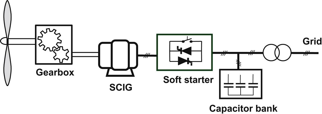
Since SCIG operates in a narrow range around the synchronous speed, this turbine operates with almost constant speed, regardless of the wind speed. This concept has been very popular because of its relatively low price for mass production, its simplicity, and its robustness. However, as the fixed-speed wind turbine concept implies that the wind speed fluctuations are converted into mechanical fluctuations and consequently into electrical power fluctuations, this type of wind turbine experiences high mechanical and fatigue stress. Furthermore it has a limited power quality control, no control of its reactive power consumption, and no speed control to optimize its aerodynamic efficiency.
A pole-changeable SCIG configuration corresponding to two rotation speeds has been used in some commercial wind turbines to increase the power production of these turbines, namely a generator winding set with typically 8 poles for low wind speeds and another one with 4–6 poles for medium and high wind speeds (typically 4–6 poles) [15,17].
8.3.2 Limited Variable-Speed Wind Turbines (Type 2)
This configuration corresponds to the limited variable-speed controlled wind turbine, known as OptiSlip or FlexiSlip. This type of wind turbine was promoted by the Danish manufacturer VESTAS since the mid-1990s up to 2006, and it has subsequently been used by the Indian manufacture SUZLON [4].
As illustrated in Fig. 8.6, in this configuration the stator of a WRIG is directly connected to the grid, whereas the rotor winding is connected in series with a variable additional rotor resistance, which is controlled optically and is changed dynamically by power electronics. By changing the rotor resistance size, the speed of the turbine can be modified and thus a variable-speed operation can be achieved by controlling the energy extracted from the WRIG rotor. The size of this resistance defines thus the range of the variable speed (typically from 0% to 10%). However, some energy extracted from the controllable resistance is dumped as heat loss. This concept still needs a soft starter to reduce the inrush current and a reactive power compensator to provide the reactive power for the magnetization of the generator. The control system includes the control of the variable resistance and the pitch control of the blades.

The advantages are a simple circuit topology without slip rings and an improved operating speed range compared to that found in Type 1. To a certain extent, this concept can reduce the mechanical loads and power fluctuations caused by gusts. Some of the disadvantages are: limited speed range, as it is dependent on the size of the additional resistance; some power is dissipated in the variable resistance as losses; and poor control of active and reactive power.
In summary, this concept partially solves the need for variable-speed operation to increase the aerodynamic efficiency. It is thus the first step toward the variable-speed wind turbine concept, which is the main dominating concept found in the market today.
8.3.3 Variable-Speed Wind Turbines With Partial-Scale Power Converter (Type 3)
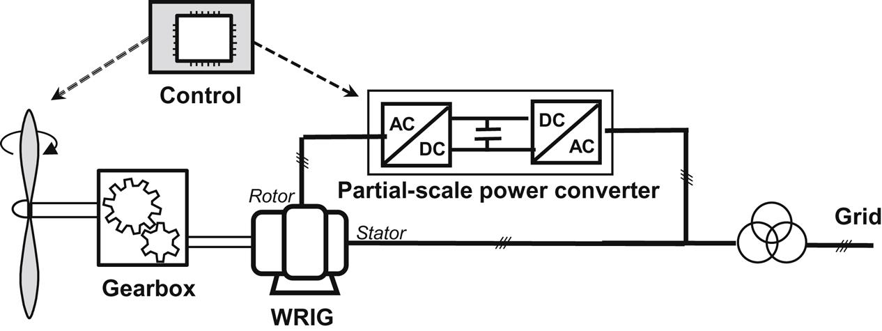
Type 3 configuration denotes the variable-speed wind turbine concept with a DFID. It uses a partial-scale back-to-back power converter connected to the rotor of the generator, typically through slip rings. This concept supports a wide speed range operation, depending on the size of the power converter [19–20].
As illustrated in Fig. 8.7, the stator is directly connected to the grid, while the rotor is connected through a partial-scale power converter (rated at approximately 30% of nominal generator power). The power rating of this partial-scale converter defines the speed range (typically ±30% around synchronous speed). This converter decouples mechanical and electrical frequencies making variable-speed operation possible as it can vary the electrical rotor frequency. Moreover, this converter performs reactive power compensation and a smooth grid interconnection and therefore this configuration needs neither a soft starter nor a reactive power compensator. A slip ring is used to transfer the rotor power by means of a partial-scale converter. The power converter controls the rotor frequency, i.e., the rotor speed, enabling thus the variable-speed operation of the wind turbine [24,25]. Beside this, it also controls the active and reactive power of the generator. The control system includes the electrical control of the converter and the pitch controller of the blades to limit the power when the turbine is above the rated power.
This concept is naturally more expensive when compared with Type 1 and Type 2 solutions, however, it is still an attractive and popular option. The power converter enables the wind turbine to act as an actively controllable unit in the power system. Compared with Type 2, the rotor energy, instead of being dissipated, can be fed into the grid by the power electronic converter. It has a wider range of dynamic speed control compared to Type 2, depending on the size of the power converter. In addition to the fact that the converter is smaller, the losses are also lower. Its main drawbacks are the additional protection of the power converter in the case of grid faults and the use of slip rings, which requires a regular maintenance, and can result in machine failure and electrical loss [24,25].
8.3.4 Variable-Speed Wind Turbines With Full-Scale Power Converter (Type 4)
Type 4 corresponds to the variable-speed concept with full-scale power converter. The generator is connected to the grid through a full-scale power converter as illustrated in Fig. 8.8. The full-scale converter allows for the control of the generator in a speed range of up to 100%. Besides this it supports a smooth grid connection and reactive power compensation over the entire speed range. Similarly to Type 3, the control system of this concept includes the electrical control to control active and reactive power, as well as the pitch control to limit the rotor speed.
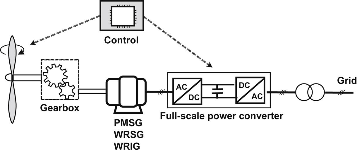
As depicted in Fig. 8.8, this concept can be implemented for different types of generator, namely the generator can be excited electrically (i.e., WRSG or WRIG) or by a permanent magnet (PMSG).
Some full variable-speed wind turbines systems have no gearbox—as depicted by the dotted gearbox in Fig. 8.8. In these cases, a direct-driven multipole generator is used [26]. The difference between wind turbines with and without gearbox is the generator rotor speed. The direct-driven multipole generator rotates at a low speed, because the generator rotor is directly connected to the hub of the aerodynamic rotor. The lower speed makes it necessary to produce a higher torque and therefore a large generator with large number of poles is needed. The wind turbine companies Enercon, Made, and Lagerwey supply this technology [27].
Compared with the Type 3 system, Type 4 has the advantages of a generator with: better efficiency; no slip rings; simpler or even removed gearbox; full power and speed controllability; as well as better grid support ability; and a less complex grid-fault ride-through capability. Some important benefits of removing the gearbox are reduced losses, lower costs, and increased reliability due to the elimination of rotating mechanical components.
Its main disadvantages are the more expensive converter (100% of rated power instead of 30%) and the losses in the converter, which are higher because all the power is processed by the power electronic converter. However the continuously decreasing cost of power electronics (roughly a factor of 10 over the past 10 years) and the absence of brushes might make this configuration the dominant one for development in the near future [28].
8.4 Conclusions
Over the years wind turbine technology has developed and reached a very reliable and advance level. The wind turbine technology have changed and progressed from fixed speed, stall controlled and with drive trains with gearboxes, to become variable speed, pitch-controlled and with or without gearboxes.
Today, the most dominating and promising wind turbine technologies are based on variable-speed operation concept. The increased interest in variable-speed wind turbines is due to the presence of the power electronics, which facilitate many attractive features, including reduced mechanical stress, increased power capture, as well as their ability to support the grid by complying with the increasingly onerous grid requirements. The presence of power electronics makes it thus possible for wind turbines to behave in a similar way to conventional power plants and hence actively support the grid.
As with all technologies, the future is difficult to predict. However, it is clear that future improvement of wind turbine technology will be strongly dependent on the further development of power electronics technology for wind power applications.