
Civil Engineering Aspects of a Wind Farm and Wind Turbine Structures
Subhamoy Bhattacharya, University of Surrey, Guildford, United Kingdom Email: [email protected]
Abstract
The aim of this chapter is to provide an overview of an overall layout of a wind farm to appreciate the multidisciplinary nature of the subject. The fundamental concepts and understanding of other disciplines and fields not directly related to civil engineering design but are necessary to carry out the design are also described with references for further study. The challenges in design of foundation are highlighted.
Keywords
Monopile; wind turbine; offshore wind farm; foundations; spacing of turbines
12.1 Energy Challenge
With the discovery of shale gas (fracking) and lowering of oil price, it is predicted that reliance of oil (often termed as oil age) may have gone. With the increasing use of electric cars and wind turbine, it may be argued that this change of moving toward low carbon energy (LCE) is irreversible and quite similar to the transition from Stone Age to Bronze Age. Offshore wind energy is considered promising technology to move toward LCE.
12.2 Wind Farm and Fukushima Nuclear disaster
12.2.1 Case Study: Performance of Near Shore Wind Farm During 2012 Tohoku Earthquake
A devastating earthquake of moment magnitude Mw9.0 struck the Tohoku and Kanto regions of Japan on March 12 at 2:46 p.m. which also triggered a tsunami, see Fig. 12.1 for the location of the earthquake and the operating wind farms. The earthquake and the associated effects such as liquefaction and tsunami caused great economic loss, loss of life, and tremendous damage to structures and national infrastructures but very little damage to the wind farms. Extensive damage was also caused by the massive tsunami in many cities and towns along the coast. Fig. 12.2A shows photographs of a wind farm at Kamisu (Hasaki) after the earthquake and Fig. 12.2B shows the collapse of pile-supported building at Onagawa. At many locations (e.g., Natori, Oofunato, and Onagawa), tsunami heights exceeded 10 m, and sea walls and other coastal defense systems failed to prevent the disaster.


The earthquake and its associated effects (i.e., tsunami) also initiated the crisis of the Fukushima Dai-ichi nuclear power plants (NPPs). The tsunami, which arrived around 50 minutes following the initial earthquake was 14 m high which overwhelmed the 10 m high plant sea walls flooding the emergency generator rooms causing the power failure of active cooling system. Limited emergency battery power ran out on March 12 and subsequently led to the reactor heating up and the subsequent meltdown leading to the release of harmful radioactive material to the atmosphere. Power failure also meant that many of the safety control systems were not operational. The release of radioactive materials caused a large scale evacuation of over 300 000 people and the cleanup costs is expected to be of the order of tens of billions of dollars. On the other hand, following/during the earthquake the wind turbines were automatically shut down (like all escalators or lifts) and following an inspection—they were restarted.
12.2.1.1 Why Did the Wind Farm Stand Up?
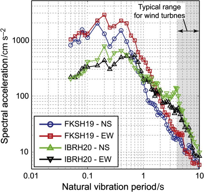
Recorded ground acceleration time-series data in two directions (North–South (NS) and East–West (EW)) at Kamisu and Hiyama wind farms (FKSH 19 and IBRH20) are presented in Fig. 12.3 in frequency domain. The dominant period ranges, of the recorded ground motions at the wind farm sites, were around 0.07–1 seconds and on the other hand the periods of the offshore wind turbine systems are in the range of 3 seconds. Due to nonoverlapping of the vibration periods, these structures will not get tuned in and as a result they are relatively insensitive to earthquake shaking. However, earthquake-induced effects such as liquefaction may cause some damages. Further details can be found in Bhattacharya and Goda [1]. Further details of dynamics of wind turbine structures together with the effects of foundation flexibility can be found in Adhikari and Bhattacharya [2,3], Bhattacharya and Adhikari [4], Bhattacharya et al. [5,6,7], and Lombardi et al. [8].
ASIDE: One may argue, had there been few offshore wind turbines operating, the disaster may have been averted or the scale of damages could have certainly been reduced. The wind turbines could have run the emergency cooling system and prevented the reactor meltdown. In this context, it is interesting to note that there are plans to replace the Fukushima NPP by a floating wind farm. The project is in advanced stage whereby involving a 2 MW semi-sub floating turbine which has been operational for few years. An innovative 7 MW oil pressure drive type wind turbine on a three-column semi-sub floater has recently been tested.
12.3 Wind Farm Site Selection
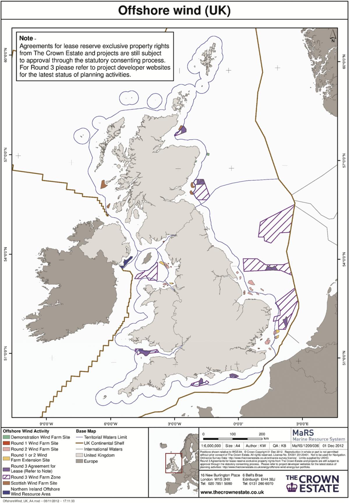
Fig. 12.4 shows the operating or planned wind farms along UK coast. Fig. 12.5 on the other hand shows wind farms along the coasts of United Kingdom and Europe together with the installed capacity. This section of the chapter will detail the considerations for choosing a particular site.

1. Wind resources: A thorough knowledge of wind resources in an area is fundamental as it allows an estimation to be made on the wind farms productivity and therefore the financial viability of the project. As a thumb rule, a project is not financially viable if the average wind speed at the hub height is below 6 m s−1 and it is considered a safe investment if the average wind speed at the hub is more than 8.5 m s−1.
2. Marine aspects: Marine aspects would include water depth, wave spectrum at the site (wave height, wave period), current and tide data, exposure to waves and sediment transport, identification of scour-related issues and if scour protection is needed. Often installation of foundations creates obstacles in the local flow pattern of water which may create turbulence leading to a scouring effect.
3. Environmental impact: For all wind farm, an EIA (Environmental Impact Assessment) must be completed as a part of the planning process and it covers the physical, biological, and human environment. This would involve collecting all types of existing environmental data and assessing for all the potential impacts that could arise due to the construction and operation of the wind farm. The impacts can range from favorable to less favorable to detrimental. Potential aspects on the biological environment include marine mammals, sea birds that use the area on a regular basis, birds from nearby areas that pass through the area during flight, fish, etc. Other aspects include effect of flora and fauna during the construction (e.g., noise due to piling or operating noise), electromagnetic field generated by subsea cable. Human environment include a change of landscape. Marine archeology aspects such as ship wreck are also taken in consideration. To carry out the assessment, samples of seabed may be collected and analyzed for worms, barnacles, or other species.
4. Power export/grid connection: One of the important deciding factor is the location of onshore grid connections. The deciding factor includes the length of submarine cable required which is dependent on the turbine layout, substation location, identify export cable routing (landfall), risk assessment of buried cables, and the transformer options—alternating or direct current.
5. Economics: Modeling of capital costs and levelized cost of energy (LCOE) is a function involving many parameters: depth of water, distance from shore, wind speed at the site, port and harbor facilities near the site, socioeconomic condition and access to skilled labor, location of national grid, and hinterland for the proposed development.
6. Navigation: This navigation risk assessment survey investigates whether or not there is a need for exclusion zone due to fishing or navigation or military operations. Cables connecting the wind farms and the export cables are buried to depths of 2–3 m to avoid risk of entanglement with nets.
7. Consents and legislations: Depending on the country, the consent requirements may change. For example, in the United Kingdom, any development more than 100 MW is classified as significant infrastructure project and requires development consent order from IPC (Infrastructure Planning Commission). These rules are subject to amendment and currently the final decision rests with the Secretary of State for Energy and Climate Change.
12.3.1 Case Studies: Burbo Wind Farm (see Fig. 12.6 for location)
The Burbo wind farm was fitted with 3 MW wind turbines of Vestas V80 make.
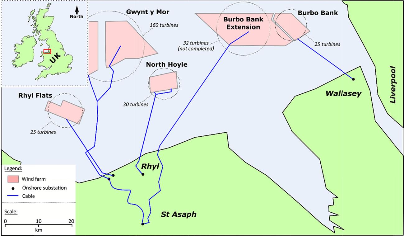
The location of Burbo wind farm is influenced by the following:
1. Average wind speed more than 7 m s−1
2. Shallow water depth 0.5–8 m at low tide
3. Good seabed condition for construction of foundation
4. Close to entrance of Mersey river
5. Proximity to Liverpool port
6. 6.4 km from Sefton coastline
7. Safe distance from navigation channel
8. Onshore export cable traveled 3.5 km underground to a substation to be fed in the grid.
The following consents were taken for Burbo:
1. Consents are Section 36 of Electricity Act 1989 for wind turbine and cabling
2. Consent under Section 34 of Coastal Protection Act 1949 for Construction in navigable waters
3. Permission from Port Authority
4. Permission under Section 57 of the Town and Country Planning Act 1990 for onshore cabling, inter connection facilities, and substation
5. License under Section 5 of Food and Environment Protection Act 1985 for the siting of Wind Turbines and deposit of scour protection material
12.3.2 ASIDE on the Economics
Currently, many of the wind farms are operating from the subsidy provided by the government. For example, in the United Kingdom, there are schemes such as cfD (Contract for Difference) are in use. However, in order to be sustainable, large wind farms are to be constructed to achieve the economy of scales with the aim to produce electricity at the lowest possible cost. Therefore the cost of electricity from different sources are compared using LCOE or SCOE (Society’s Cost of Energy). As many of the installation, operation and maintenance (O & M) will be carried out in rougher waters, time in construction is also a driving factor for site selection. Therefore every cost that increases part of the construction has to be lowered in such a manner that an optimal method for the construction and installation will be established.
12.4 General Arrangement of a Wind Farm
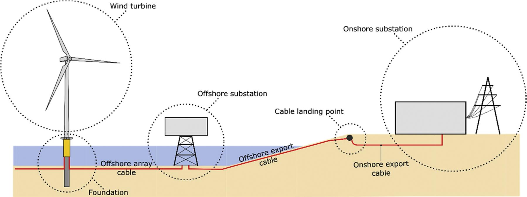
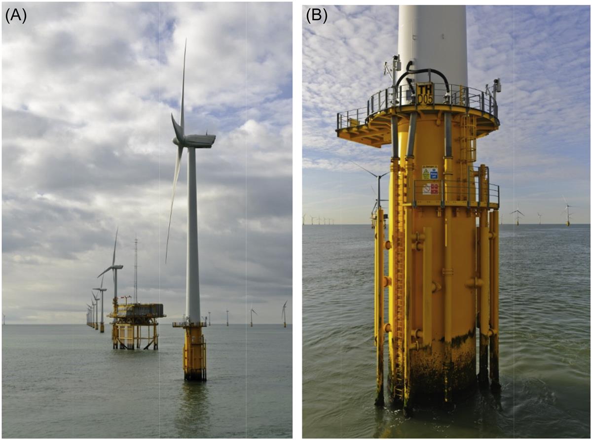
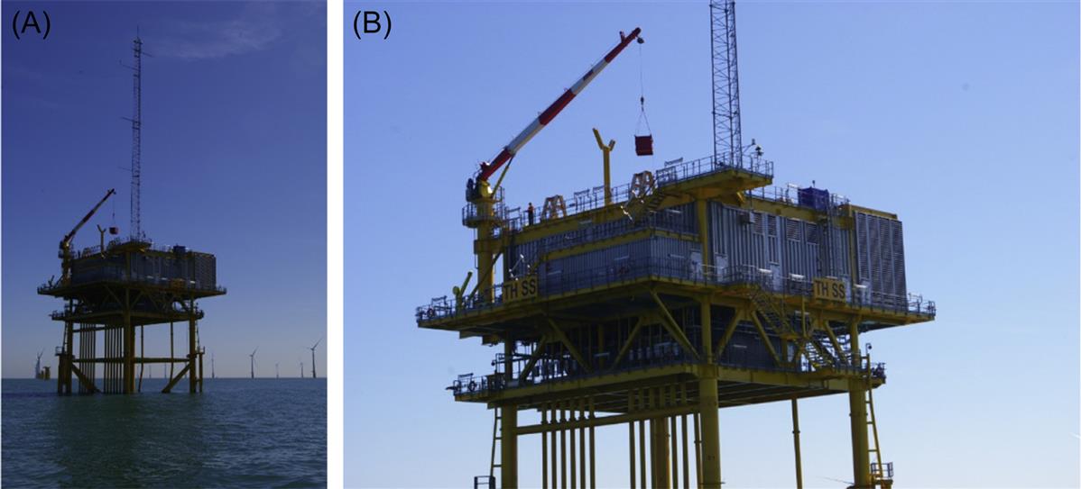
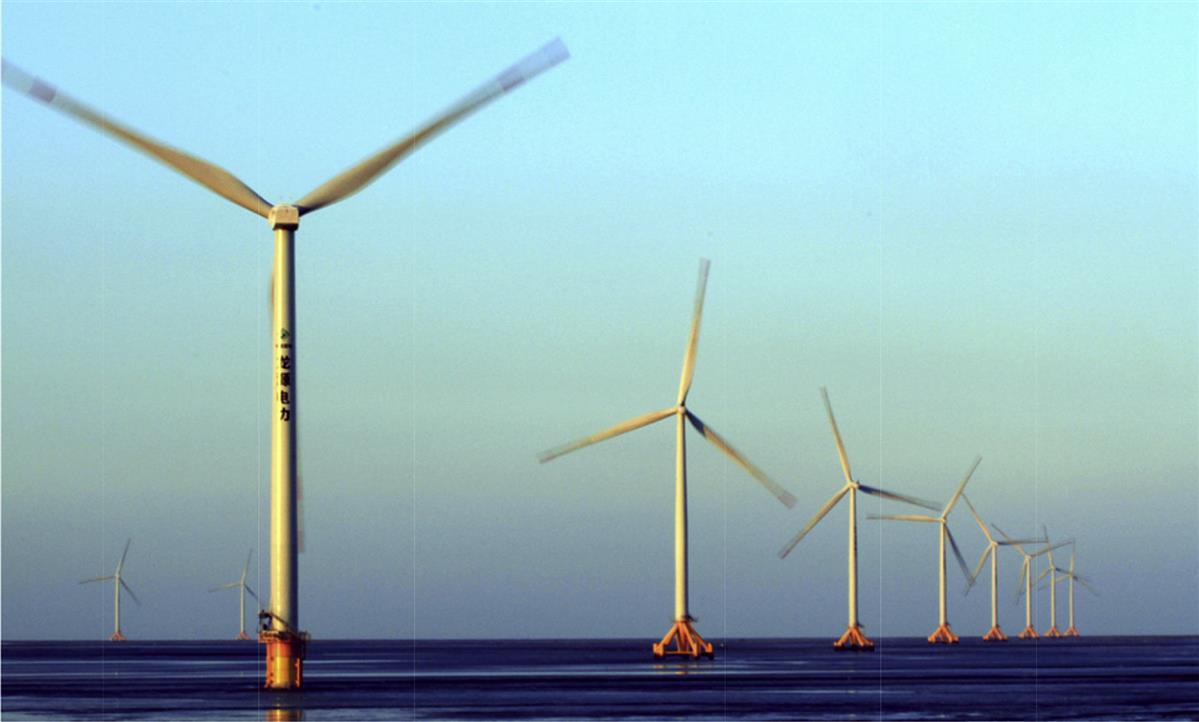
Fig. 12.7 shows the components of a typical wind farm. The turbines in a wind farm are connected by interturbine cables (electrical collection system) and are connected to the offshore substation. There are export cables from offshore to the onshore. Figs. 12.8 and 12.9 show photographs of some of the components. Fig. 12.8A shows the photograph of a wind farm with many wind turbines and a substation. Fig. 12.8B shows the details of the substructure of a monopile with J tubes for the electrical collection system. Fig. 12.9 shows the photograph of a jacket supported substation.
12.5 Choice of Foundations for a Site
The choice of foundation will depend on the following: site conditions (wind, wave, current, seabed condition, ground profile, water depth, etc.), available fabrication and installation expertise, operation and maintenance, decommissioning laws of the land, and finally economics. The definition of an ideal foundation is as follows:
1. A foundation which is capacity or “rated power” specific (i.e., 5 or 8 MW rated power) specific but not turbine manufacturer specific. In other words, a foundation designed to support 5 MW turbine but can support turbines of any make. There are other advantages in the sense that turbines can be easily replaced even if a particular manufacturer stops manufacturing them.
2. Installation of a foundation is not weather sensitive, i.e., not dependent of having a calm sea or a particular wind condition. The installation of the first offshore wind farm in the United States took more time due to the unavailability of a suitable weather window.
3. Low maintenance and operational costs, i.e., needs least amount of inspection. For example, a jacket type foundation needs inspection at the weld joints.
It is economical to have a large number of turbines in a wind farm to have the economy of scales and therefore it also requires a large area. If the continental shelf is very steep, grounded (fixed) turbines are not economically viable and a floating system is desirable.
12.6 Foundation Types
Foundations constitute the most important design consideration and often determines the financial viability of a project. Typically foundations cost 25%–34% of the whole project and there are attempts to get the costs down. Many aspects must be considered while choosing and designing the foundation for a particular site. They include: ease to install under most weather conditions, varying seabed conditions, aspects of installation including vessels and equipment required, and local regulations concerning the environment (noise). Fig. 12.10 shows a schematic diagram of a wind turbine supported on a large diameter column inserted deep into the ground (known as monopile). This is the most used foundation so far in the offshore wind industry due to its simplicity.
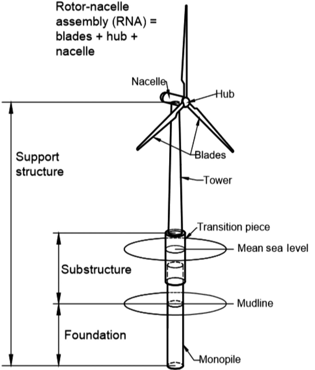
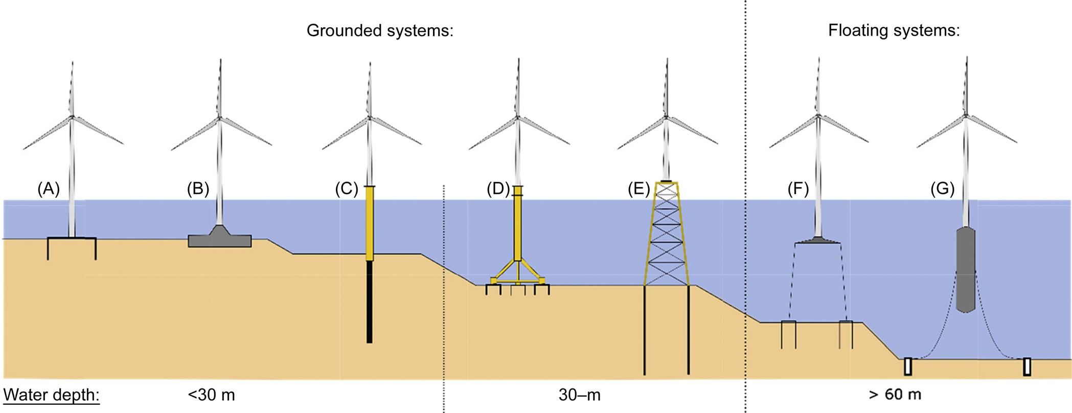
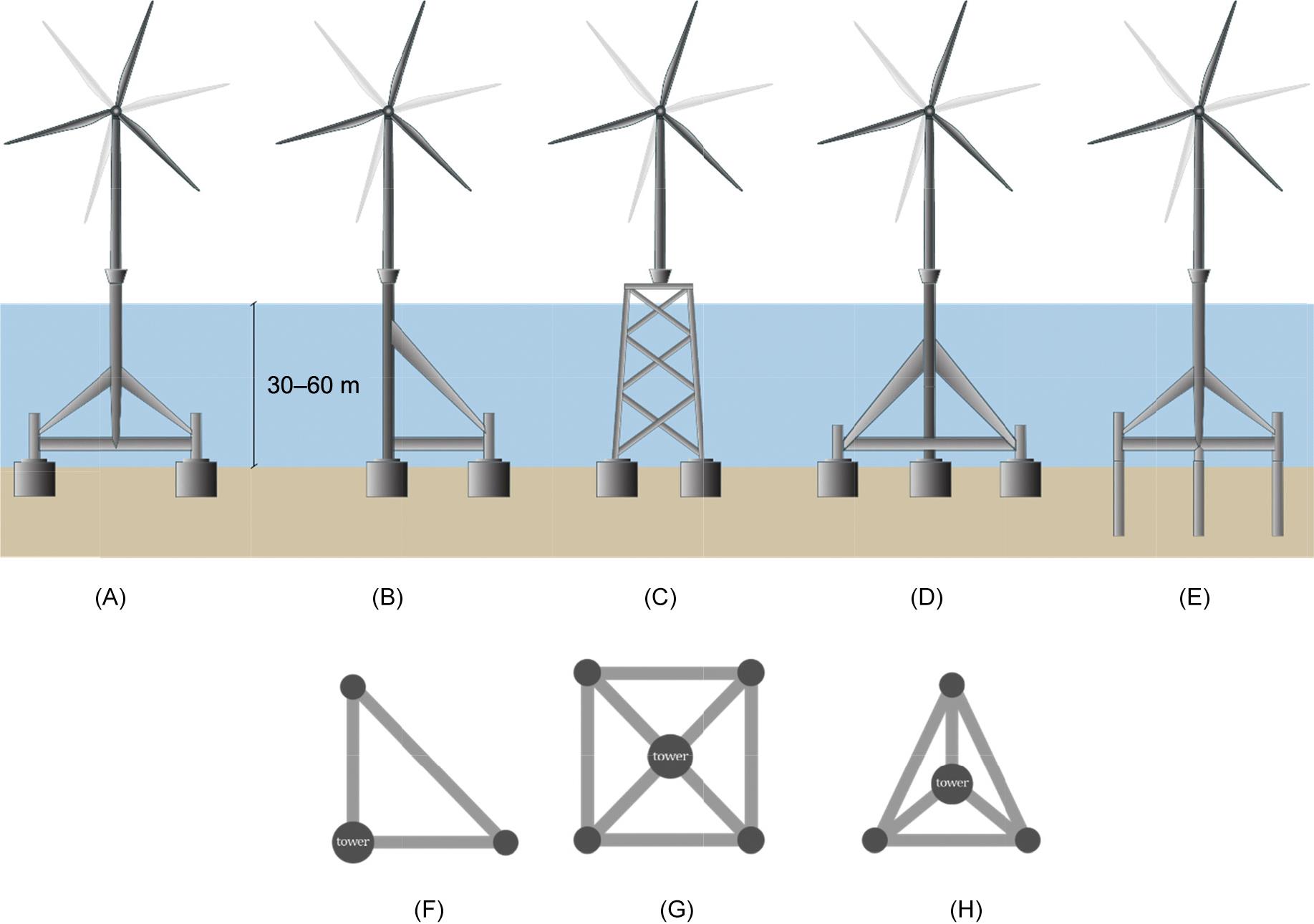
Fig. 12.11 shows the various types of foundations commonly used today for different depths of water. Monopiles (Fig. 12.11C), gravity-based foundations (Fig. 12.11B), and suction caissons (Fig. 12.11A) are currently being used or considered for water depths of about 30 m. For water depth between 30 and 60 m, jackets or seabed frame structures supported on piles or caissons are either used or planned. Floating system is being considered for deeper waters, typically more than 60 m. However, selection of foundations depends on seabed, site conditions, turbine and loading characteristics, and the economics and not always on the water depth.
The substructure can be classified into two types:
1. Grounded system or fixed structure where the structure is anchored to the seabed. Grounded system can be further subdivided in two types in the terminology of conventional foundation/geotechnical engineering: shallow foundation (gravity base solution and suction caisson) and deep foundation.
2. Floating system where the system is allowed to float is anchored to the seabed by a mooring system. Floating systems have certain ecological advantage in the sense that the foundations leave a very low seabed foot print, easy to decommission and maintain as the system can be deanchored and floated out to a harbor.
12.6.1 Gravity-Based Foundation System
The gravity foundation is designed to avoid uplift or overturning, i.e., no tensile load between the support structure and the seabed. This is achieved by providing adequate dead load to provide stability to the structure under the action of overturning moments. If the dead loads from the support structure and the superstructure (tower + RNA) are not sufficient, additional ballast will be necessary. The ballast consists of rock, iron ore, or concrete. Installation of these foundation often requires seabed preparation to avoid inclination. The gravity-based structure in most cases are constructed in situ concrete or with precast concrete units. The gravity-based concept can be classified into the two types depending on the method of transportation and installation:
1. Crane free solution also known as “float-out and sink” solution: These types of foundations will be floated (either self-buoyant or with some mechanism) and towed to the offshore site. At the site, the foundation will be filled with ballast causing it to sink to the seabed. This can be attractive solutions for sites having very hard or rocky soil condition. This operation does not require a crane and thus known as a “crane free” solution.
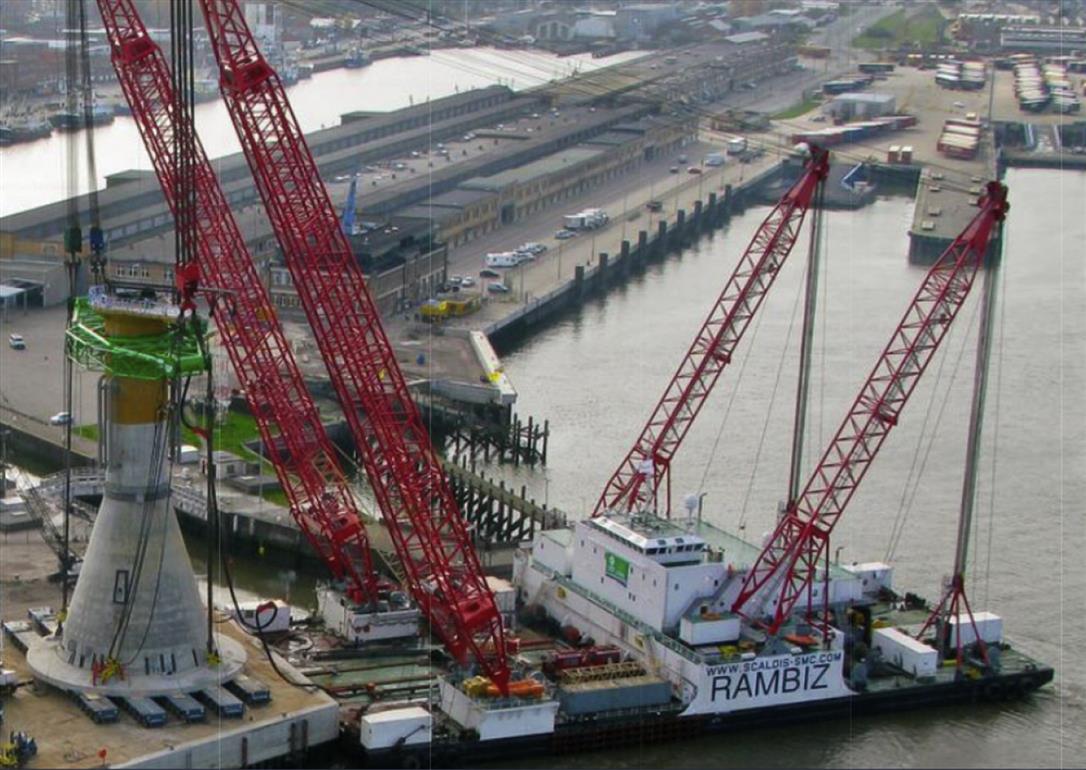
2. Crane-assisted solution: In this type, the foundation does have the capacity to float and is therefore towed to the site onboard a vessel. They are then lowered to the seabed using cranes. An example is the Thornton Bank, shown in Fig. 12.12 where the shape of the gravity-based substructure is compared to a champagne bottle.
12.6.2 Suction Buckets or Caissons
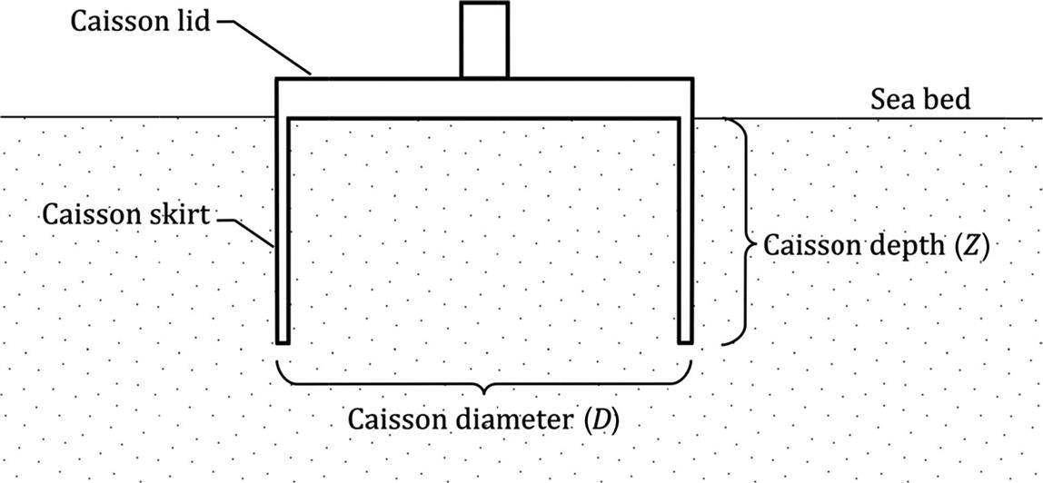
Suction buckets (sometimes referred to as suction caissons) are similar in appearance to a gravity-based foundations but with long skirts around the perimeter. Essentially, they are a hybrid foundation taking design aspects from both shallow and pile foundation arrangements. A caisson consists of a ridged circular lid with a thin tubular skirt of finite length extending below, giving it the appearance of a bucket. Typically, such foundations will have a diameter to length ratio ![]() of around 1 making them significantly shorter than a pile but deeper than a shallow foundation. A sketch of a suction caisson with terminology can be seen in Fig. 12.13. Suction caissons themselves are a fairly recent development in the offshore industry. Caissons first came into use around 30 years ago as foundation structure for offshore oil and gas production platforms.
of around 1 making them significantly shorter than a pile but deeper than a shallow foundation. A sketch of a suction caisson with terminology can be seen in Fig. 12.13. Suction caissons themselves are a fairly recent development in the offshore industry. Caissons first came into use around 30 years ago as foundation structure for offshore oil and gas production platforms.
12.6.3 Pile Foundations
Single large diameter steel tubular pile also known as monopile is the most common form of foundation for supporting offshore wind turbines. Fig. 12.14 shows the monopile type of foundation which is essentially a large steel pile (3–7 m in diameter) driven into the seabed with a typical penetration depth of 25–40 m. A steel tube, commonly called the transition piece (TP) is connected to the steel pile and the tower is attached to it. The TP supports the boat landings and ladders used for entering the turbine. Currently, this type of foundation is extensively used for water depths up to 25–30 m.
These foundations can be reliability driven into the seabed using a steam or hydraulically driven hammer and the practice is very standardized due to the offshore oil and gas industry. The handling and driving of these foundations requires the use of either floating vessels or jack-up vessels which must be equipped with large cranes, a suite of hammers, and drilling equipment. If the ground profile at the site contains stiff clay or rock, drive–drill–drive procedure may need to be adopted. Pile driving results in noise and vibrations. Therefore the installation of the turbine (Nacelle and Rotor) is always carried out after the piling has been completed.
12.6.4 Seabed Frame or Jacket Supporting Supported on Pile or Caissons
Often a seabed frame or a jacket supported on piles or caissons can act as support structure and they can be classified as multipods (Fig. 12.15). Multipods have more than one point of contact between the foundation and the soil. Soil embedded elements may include flexible piles, gravity bases, and suction caissons can also be used. Fig. 12.16 shows an example from a wind farm in China. Further details on the foundations used in China can be found in Chapter 13, Civil Engineering Challenges Associated With Design of Offshore Wind Turbines With Special Reference to China.
12.6.5 Floating Turbine System
The floating system can be classified into three main types (Fig. 12.17A):
1. Mooring stabilized TLP (tension leg platform) concept: This type of system is stabilized with tensioned mooring and is anchored to the seabed for buoyancy and stability.
2. Ballast stabilized spar buoy concept with or without motion control stabilizer: This type of system will have a relatively deep cylindrical base providing the ballast whereby the lower part of the structure is much heavier that the upper part. This would raise the center of buoyancy about the center of gravity of the system. While these are simple structures having a low capex cost, it needs a deeper draft, i.e., deeper water and is not feasible in shallow water. Motion stabilizer can be used to reduce the overall tilt of the system
3. Buoyancy stabilized semi-submersible: This concept is a combination of ballasting and tensioning principle and consumes a large amount of steel (Fig. 12.17B).

There are varieties of anchors that can be used to moor the floating system and they can be classified into surface anchors and embedded anchors. Example of surface anchors is a large heavy box containing rocks or iron ore and the holding capacity depends on the weight of the anchor itself and the friction between the base of the anchor and the seabed. On the other hand, examples of embedded anchors include anchor piles (Fig. 12.17A–C) which are floating wind turbine concepts suitable for deeper waters. Fig. 12.17B shows the floating concept (semi-sub) implemented in a wind farm in Japan (offshore Fukushima) and Fig. 12.17C shows the Hywind concept (spar).
12.7 Site Layout, Spacing of Turbines, and Geology of the Site
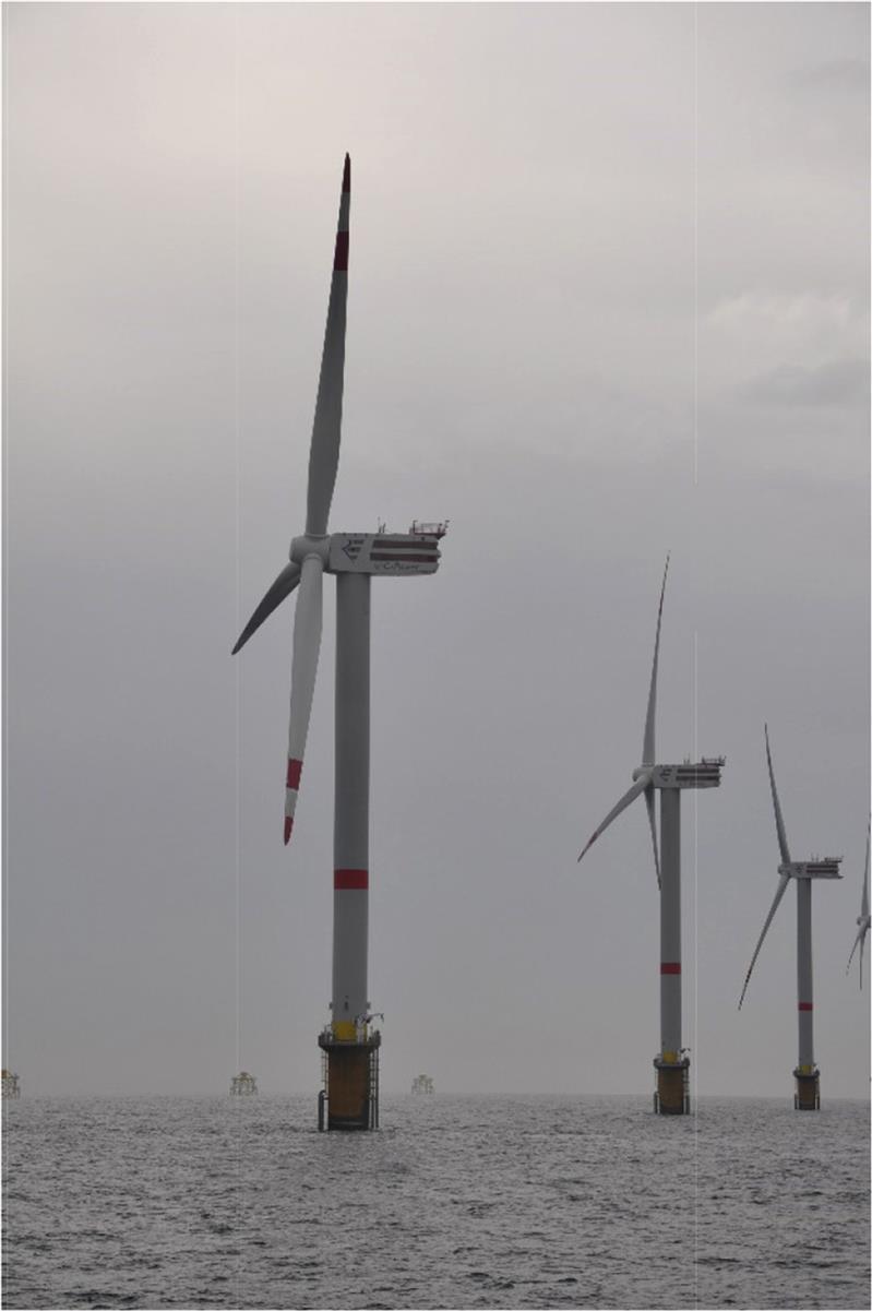
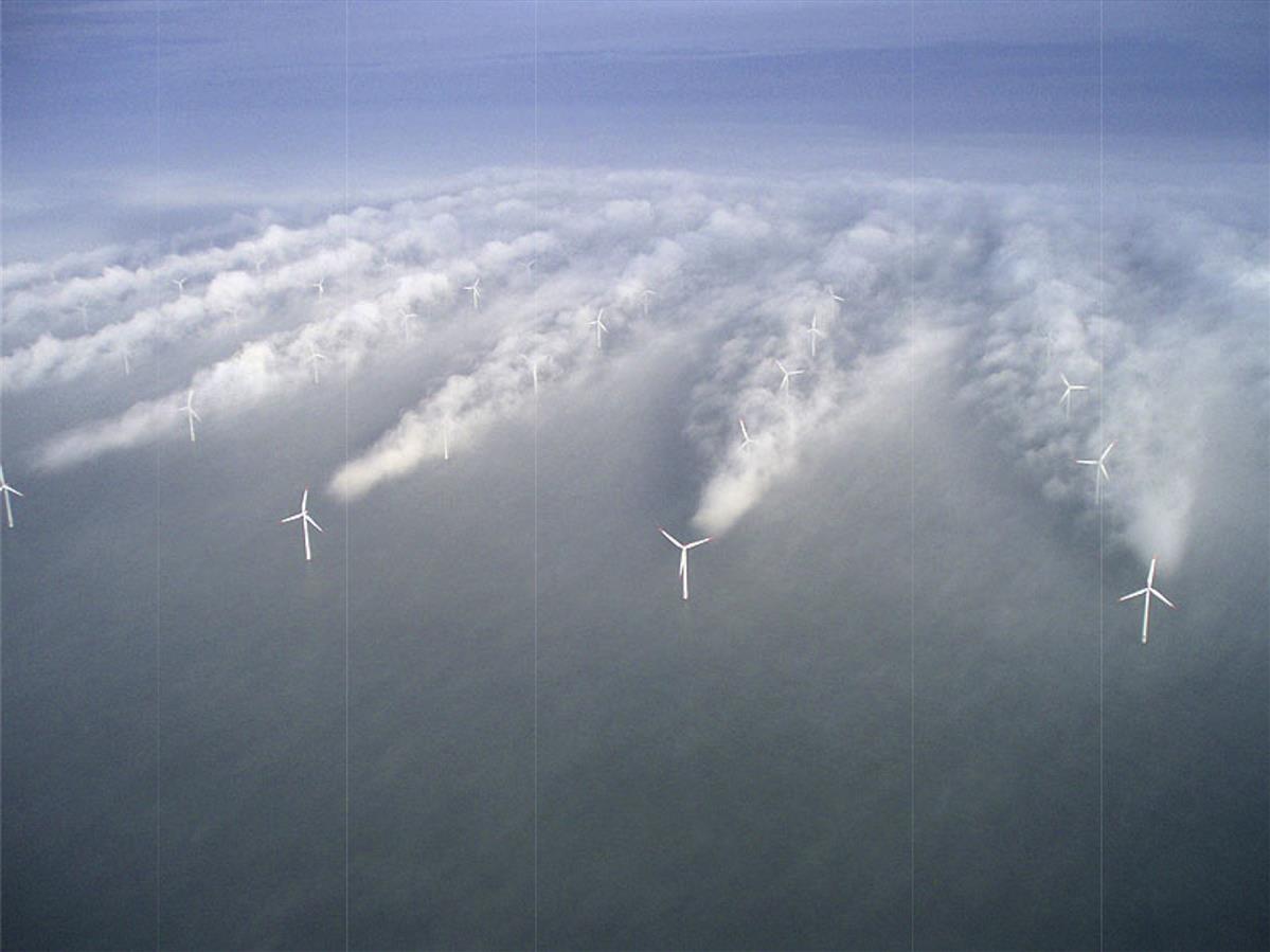
Wind turbines in a wind farm are spaced to maximize the amount of energy that can be generated without substantially increasing the CAPEX (Capital expenditure, i.e., upfront cost). If the farm is significantly spread out, i.e., large spacing of the turbines, the interarray cable length will increase. The spacing is therefore an optimization problem between compactness of the wind farm (which minimizes the CAPEX cost due to subsea cables) and the adequate separations between turbines so as to minimize the energy loss due to wind shadowing from upstream turbines. Fig. 12.18 shows the aerial photo of wake turbulence behind individual wind turbines that can be seen in the fog of the Horns Rev wind farm off the Western coast of Denmark.
The geometric layout of a wind farm can be a single line of array, or a square or a rectangular configuration. Due to advanced methods for optimization having different constraints as well as site conditions, different layout pattern is increasingly being used. Typically, the spacing between turbines is equivalent to 3–10 times the rotor diameter and it depends on the prevailing wind direction. The spacing should be larger than 3–4 rotor diameter perpendicular to the prevailing wind direction and 8–10 diameters for direction parallel to the wind direction. For example, for a prevailing South Westerly wind direction (which is typical of Northern Ireland), a possible site layout for a wind farm located in the area is shown in Fig. 12.19. The spacing along the wind direction is kept at 6 times the rotor diameter (6D) but for across the wind, the spacing can be kept bit lower (4D).

Due to the large spacing of the turbines (typically 800–1200 m apart), a small to medium size wind farm would extend over a substantial area. Typical size for a modern day wind farm is 20 km×6.5 km (e.g., Sandbank wind farm of German North Sea). Due to the large coverage of area for a wind farm, there may be significant variation in the geological and subsurface conditions as well as practical restraints. Examples include sudden drop in the sea floor causing change in water depth, paleochannels, change in ground stratification, submarine slopes, presence of foreign objects such as shipwrecks, location of important utility lines (gas pipeline, fiber optic cables), etc. A detail site investigation programme consisting of geotechnical and geophysical tests is carried out to establish a 3D geological model which often dictates the layout.
12.7.1 Case Study: Westermost Rough
Fig. 12.20 shows the ground profile from Westermost Rough Offshore Wind Farm (located in the United Kingdom) approximately 8 km off the Yorkshire coast, near the town of Withernsea following Kallehave et al. [9]. It may be observed that the monopile passes through different geology denoted in the figure. Therefore the foundation consists of monopiles of varying length, wall thickness and diameter. This also shows that not only geotechnical but also geological study needs to be carried out.

12.7.2 Economy of Scales for Foundation
Monopiles are currently preferred for water depths up to 30 m. The simple geometry makes it possible to automate the manufacturing and fabrication process and the typical manufacturing cost related to monopile steel is 2 euros per kilogram. Welding can be carried out by robots and installation is relatively simple. However, if the diameter become large (knowns as XL or XXL piles which are over 8 m in diameter and weighs 1200 tonnes), the transportation and installation becomes challenging and limits the number of installation contractors that can carry out the work. Innovations are underway to install large diameter piles using a vibro method where a foundation is installed through the vibration of the soil and thus effectively liquefying the soil around it.
An alternative to large diameter monopiles is the 3 or 4 legged jacket on small diameter piles. Steel for jackets cost around 5 euros per kilogram to manufacture, which is more than double that of monopiles due to many tubular joints which are often welded manually.
Gravity-based foundations are cheaper to manufacture as compared to steel but requires a large fabrication yard and storing area. As concrete foundations will be much heavier than an equivalent steel foundation, large crane and vessels are required for installation. For an offshore site where the surface ground is rock, gravity-based structure will be a preferred choice; this is the situation in French waters.
Due to the vast size of a wind farm, there will be varying seabed condition including water depth and distance from the shore. As a result, the loads on the foundations will change and ideally the best design will be to design each foundation individually which will give rise to a customized foundation design for each turbine location. However, from economic point of view, it is desirable to have few foundation types so that the overall economy is achieved and the process of fabrication and installation can be carried out efficiently using the same installation vessel. Most North European developers prefer one type of foundation (either monopiles or jackets) on a site. This consideration often dictates the layout of the farm to avoid deeper water or soft locally available mud.