
Multielement Airfoils for Wind Turbines
Adam M. Ragheb, Michael S. Selig, University of Illinois at Urbana-Champaign, Urbana, IL, United States Email: [email protected], [email protected]
Abstract
The thick root airfoils of modern wind turbines, with current technology designs reaching 45% thickness, are incapable of producing high lift, and as a consequence, the blades are aerodynamically and structurally suboptimal. Additionally, the road-transportable blade length is limited to between 53 and 62 m depending on the specific blade geometry. The use of multielement airfoil arrangements on utility-scale wind turbine blades has the potential to allow for (1) improving aerodynamics near the hub section, (2) improving the structural arrangement, and (3) creating natural disconnect points that ease transportation constraints. Segmented blades are already being used by wind turbine manufacturers, including Gamesa and Enercon, to solve transportation constraints. Studies that investigated candidate multielement airfoil configurations to serve as an aerodynamic fairing for an assumed spar cap yielded promising results. The use of multielement airfoils for wind turbines can increase the blade efficiency, provide better start-up performance, and offer gross annual energy production (GAEP) benefits.
Keywords
Wind; wind power; aerodynamics; multielement; airfoils; segmented blades; transportation; high lift; flap; slat
11.1 Introduction
Multielement airfoil configurations hold the potential to increase the aerodynamic performance of the inboard section of a wind turbine blade [1]. In addition to improving the blade root aerodynamics, multielement airfoil arrangements also show promise to improving the transportability of large wind turbine blades and creating the ability to increase the spar cap separation to allow for an improved structural arrangement of the blades. Modern utility-scale wind turbines (1.5–10 MW rated power) have cut-in wind speeds between 3 and 5 m s−1 and do not begin to operate at their rated power until wind speeds of between 10 and 15 m s−1 are achieved. Increasing the lift coefficient of the inboard section of a wind turbine blade should aid in starting the wind turbine at lower speeds and will allow the turbine to produce its rated power at a lower wind speed. The turbine will be aided in starting at low speeds, also known as lowering the cut-in wind speed, through a larger tangential force coefficient Ct, which is a direct result of an increased lift coefficient Cl [2]. The tangential force coefficient, Ct, is the force coefficient that contributes to the torque of the wind turbine, and it is oriented normal to the rotor axis of rotation and is positive in the direction of the blade leading edge. The lift coefficient Cl is an aerodynamic quantity that is normal to the local flow. The resultant of the lift and drag coefficients may be decomposed into the aforementioned tangential force coefficient and the normal force coefficient Cn, which is parallel to the rotor axis of rotation. Additionally, the improvement of the blade root aerodynamics will allow for the axial induction factor to be increased to the Betz limit ideal operating condition of one-third [3] over a larger portion of the inboard section of the blade. These improvements would in turn increase the power output, increase the capacity factor, and open up new locations for wind turbines that would otherwise be unsuitable for wind turbine placement. This chapter will discuss the benefits of multielement wind turbine blades as they relate to transportation and structural concerns, cover the results of multielement wind turbine blade studies conducted at the University of Illinois at Urbana-Champaign, and finally, will review multielement wind turbine blade work conducted by other research groups.
11.2 Transportation Benefits
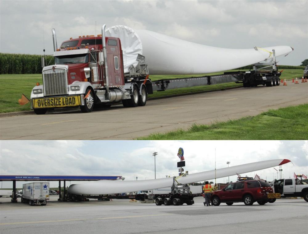
In regard to transportation, current wind turbine blades appear to have reached the maximum size that can be easily transported. Constructing a longer or thicker root section may render the blade incompatible with current transportation infrastructure. The most substantial limit in the design of utility-scale is the transportation cost, which grows rapidly for lengths of over 46 m and reaches prohibitive levels for blades over 61 m long [4,5]. Multielement configurations will allow for natural disconnect points on the blades, allowing the root section to be disassembled from the rest of the blade and the components to be transported to the wind farm site for assembly. These natural disconnect points will result in a simplification of the transportation process for a given blade radius and the ability to transport blades of larger radii as segmented blade sections. Fig. 11.1 presents a photograph of a wind turbine blade loaded onto an American Wind Transport Group, LLC truck for transport by road and depicts the difficulty of refueling a truck while transporting a wind turbine blade.
The use of segmented blades for wind turbine applications has only recently begun, albeit for single-element airfoils. The first commercial wind turbine to use a segmented blade is the Gamesa G128, a wind turbine that is offered in 4.5 and 5.0 MW versions. The patented technology, termed “InnoBlade,” connects the two pieces of the 62.5 m blade with approximately 30 bolt channel fittings that are integrated into the blades [6]. By using a sectioned blade, Gamesa advertises that the tooling and equipment used to transport their 2–2.5 MW wind turbines can be used to transport the blades of the 5.0 MW wind turbine platform since no component is longer than 35 m [7].
Enercon also utilizes a segmented blade design on both their E115 and E126 wind turbines, pairing the technology with their innovative direct-drive annular generator [8]. The Enercon E115 blade comprises two glass fiber reinforced epoxy sections with an inner section of approximately 12 m in length and an outer section with a length of approximately 44 m. The 7.5 MW E126 wind turbine, on the other hand, has its inner blade section comprised of a primarily steel structure [9].
Multielement configurations will allow for natural disconnect points on the blades where the blade airfoils transition from a multielement arrangement to a single element, allowing the root section to be disassembled from the rest of the blade and the components to be transported to the wind farm site for assembly with little or no additional weight. These natural disconnect points will result in a simplification of the transportation process for a given blade radius or the ability to transport blades of larger radii. Additionally, if a blade were to be significantly damaged as a result of a hailstorm or leading edge erosion [10], components could more-easily be transported to the turbine location and if applicable, only the damaged section of the blade would need to be replaced.
11.3 Structural Benefits
Current single-element wind turbine blades suffer from competing aerodynamic and structural requirements [11–13]. Aerodynamic requirements call for thinner airfoils while structural requirements call for thicker airfoils. These competing aerodynamic and structural requirements effectively cap the maximum size of wind turbine blades. The power rating of a wind turbine is proportional to the blade radius squared [3] while the weight and the required structural strength of a blade is proportional to the blade volume in accordance with the square-cube law; as a result, the blade weight grows faster than the power rating. The fact that the weight grows more rapidly than the power rating implies that a maximum economical size exists under the current structural configuration. In a multielement configuration with a strut (i.e., the well-separated cases of reference [1]), the strut and main element act in a biplane-like manner where an increased vertical separation between the two elements will yield an aerodynamic benefit as well as an increase in the spar cap separation. An increase in spar cap separation is desirable because it offers increased structural benefits, including a stronger structure and decreased tip deflections [11–13]. By offering separate airfoil fairings for the upper and lower spar caps, well-separated multielement arrangements are able to solve the problem of competing aerodynamic and structural requirements. Multielement airfoil configurations may be tailored to facilitate even greater spar cap separations that could greatly improve the structural efficiency of the next generation of large multimegawatt wind turbines; this improved structural efficiency would effectively further raise the cap on the maximum achievable size of wind turbine blades. It should be noted that this style of multielement wind turbine blade would allow the design requirements for structural and aerodynamic considerations to be aligned whereas they currently compete with one another. This alignment of the design goals is due to the fact that in a biplane-like arrangement, the aerodynamic performance can be improved by increasing the vertical distance between the upper and lower blade sections; increasing the vertical distance is also desirable from a structural standpoint because the bending strength of an I-beam is proportional to the separation distance cubed. Limits, however, would eventually be reached on such blades in regard to torsional rigidity and tower clearance.
Structural investigations also attest to the benefits of multielement airfoil arrangements for the inboard sections of wind turbines. Studies conducted at the University of California, Los Angeles on a wind turbine blade with a biplane airfoil arrangement near the root show that such an arrangement is more structurally efficient than a single-element blade at loads from the incoming wind [13]. Compared to a conventional wind turbine blade, the use of a biplane arrangement makes it possible to construct a lighter blade that has an equal tip deflection [12]. While a biplane configuration of two NASA-designed 14%-thick supercritical SC(2)-0714 airfoils was found to have less total drag than the thick, single-element FFA-W3-301 wind turbine airfoil, a 30.1%-thick airfoil designed by The Aeronautical Research Institute of Sweden (FFA), one aspect of such a configuration that needs further study is the effect of the aerodynamic drag of the joint where the multielement arrangement would transition to a single-element arrangement [12]. It should be noted, however, that the SC(2)-0714 airfoil is designed to operate in the transonic regime; the airfoil was selected for study by Roth-Johnson and Wirz [12] because its box-like profile was expected to provide it with large principle area moments of inertia.
11.4 Multielement Wind Turbine Blades
For the studies summarized in this chapter, the DU 00-W-401 airfoil geometry, a 40.1%-thick wind turbine airfoil designed by the Delft University Wind Research Institute in 2000, was used as a benchmark for gauging nominal spar cap spacing. Based on this geometry and examples in the literature [14] the location and dimensions of the top and bottom spar caps were approximated. The DU 00-W-401 airfoil section with the concept spar cap geometry is shown in Fig. 11.2. The 40.1% thick DU 00-W-401 wind turbine root airfoil was reported to have a maximum lift coefficient Cl,max value of around 1.04 at a Reynolds number Re=3.0×10⁶ and α=8.5 degrees [15].
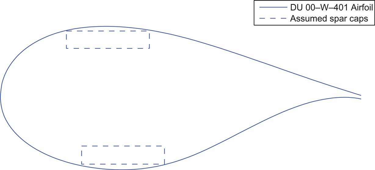
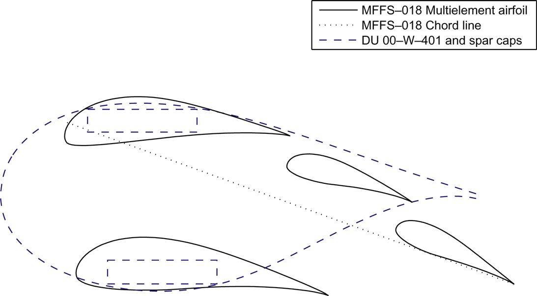
Normalized by the unit chord length of the airfoil, the nondimensional spar caps shown in Fig. 11.2, measure 0.23×0.048 with a separation of 0.27. The front of the top spar cap is located at x/c=0.183 (18.3% of the distance from the airfoil leading edge to the trailing edge), and the front of the lower spar cap is located at x/c=0.225. This concept spar cap geometry of these multielement configuration designs was greatly oversized to add ample flexibility and margin for the process of transformation of this concept from an academic study into a mass-producible commercial product. Two multielement airfoil configuration concepts are presented in this chapter. These configurations were designed with various combinations of slats, flaps, and struts arranged around a main airfoil element. In the second multielement geometry, the main airfoil element served as a fairing for the upper spar cap while the strut element faired the lower spar cap. Slats and flaps were located fore and aft of the main and/or strut elements, respectively. The entire arrangement was scaled to have a unit chord across all elements as shown in Fig. 11.3 and by the dotted chord line in Fig. 11.4. This scaling was done in order to allow for a direct comparison of the airfoil and multielement configuration lift coefficients.
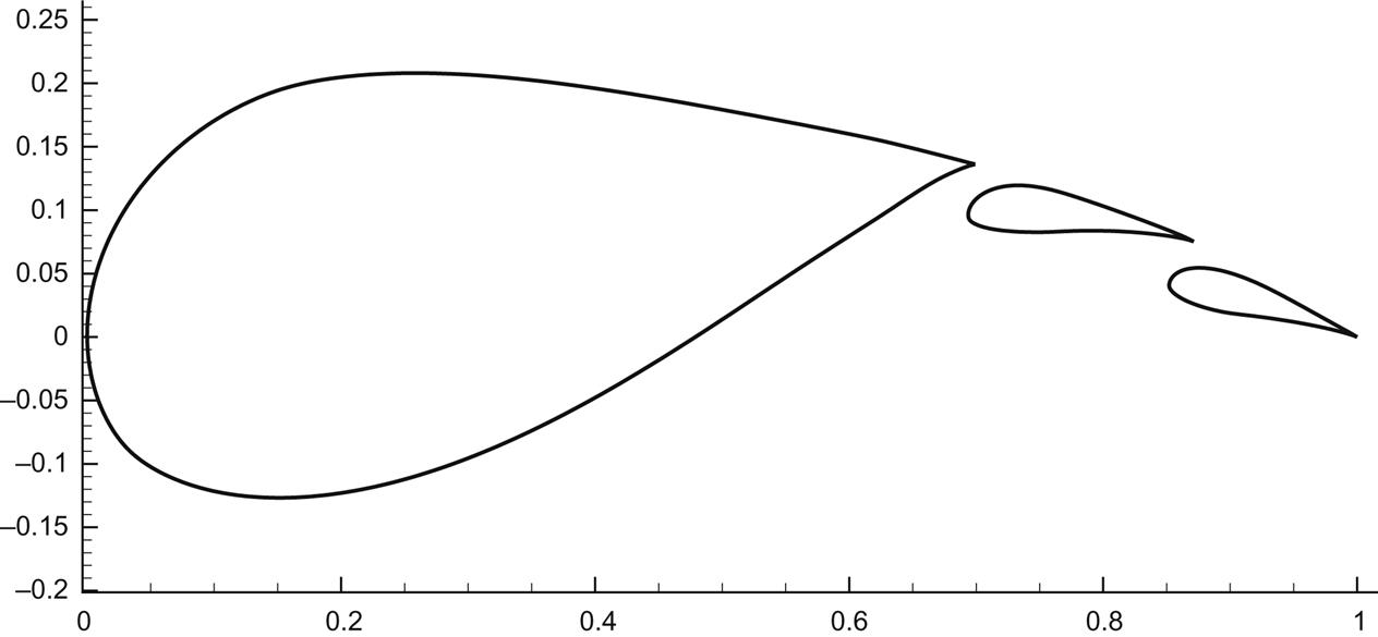
The first multielement arrangement consists of a closely coupled multielement airfoil arrangement with a main element of similar thickness to existing wind turbine airfoils. The arrangement was denoted as the MFF arrangement; it contains a Main element and two Flap elements. This closely coupled arrangement was used in order to define an intermediate design concept between existing megawatt-scale wind turbine blade designs and a completely-redesigned well-separated multielement wind turbine blade as proposed by Ragheb and Selig [1]. Computational fluid dynamics (CFD) studies were conducted on this multielement airfoil by reference [16], and wind tunnel tests were tested on this geometry and derivatives of it in reference [17]; the airfoil geometry is presented in Fig. 11.3.
Narsipur et al. [16] conducted CFD analysis of the MFF-089 multielement geometry in ANSYS FLUENT at Re=1×10⁶. While a number of different gap, overhang, and flap deflection angles were tested, all CFD simulations of the configurations produced lift coefficient Cl values nearing 3.0 at an angle of attack of 18 degrees; values of the drag coefficient Cd at this angle of attack were around 0.035.
The second, more radical multielement arrangement presented herein consists of a double-slotted flap aft of a thin main element with a strut located beneath the main element. This configuration is presented in Fig. 11.4. The thin main element serves as an aerodynamic fairing for the upper spar cap and the strut element serves as a fairing for the lower spar cap. This well-separated multielement airfoil arrangement was named the MFFS and contains a Main element (M), two Flap elements (FF), and a Strut element (S). The MFFS family of designs evolved from the MFFS-018 arrangement, depicted in Fig. 11.4, of Ragheb and Selig [1] to offer an increased Cl/Cd when compared to the Delft University family of wind turbine airfoils [15,18] at Cl values up to 1.7. This configuration was developed with the goal of further increasing the lift over that of a single-flapped multielement arrangement. The second flap increased the camber relative to a single-slotted multielement airfoil configuration.
An inviscid multipoint inverse airfoil design method was used to develop and refine the multielement configurations. The PROFOIL [19–21] code and associated MFOIL graphical user interface was used to develop the configurations and to fine-tune the velocity profiles. The inviscid velocity profiles were adjusted in order to avoid the presence of strong adverse pressure gradients, which would be expected to lead to flow separation in an experimental or viscous computational investigation. The MFOIL user interface allows one to easily and rapidly account for changes to the structural constraints. The relocation of a spar cap or the addition of a rear spar would not preclude the user from getting significantly better aerodynamic results when compared to existing thick blade root airfoils, allowing a very great degree of freedom in the structural design of the blade. These multielement configurations were then analyzed using the viscous MSES [22–24] multielement computer program. The MSES code is an inviscid-viscous coupled solver. The performances, especially the Cl/Cd ratios and the stall characteristics, were compared with those of existing thick blade root airfoils at Re=3×10⁶, which corresponds to the values encountered on utility-scale wind turbines.
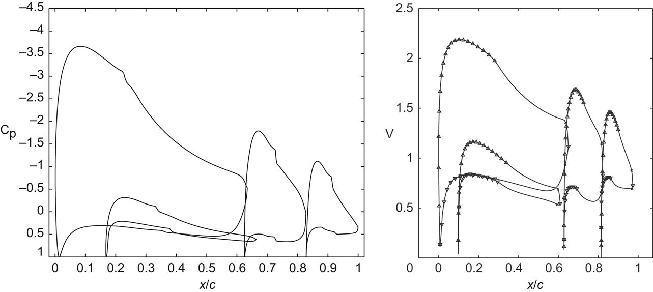
Fig. 11.5 presents the flow properties across the multielement configuration. The left-hand figure of this pair of figures shows the pressure coefficient Cp distributions of the individual elements at Re=3.0×10⁶ and angle of attack for the maximum lift-to-drag ratio, αCl/Cd,max, as determined by MSES [24]. The right-hand figure shows the nondimensional inviscid velocity distributions from MFOIL at the same α. These figures demonstrate that the adverse pressure gradients of the multielement arrangement were reasonable and no undesirable effects arose in the viscous case at the design point.
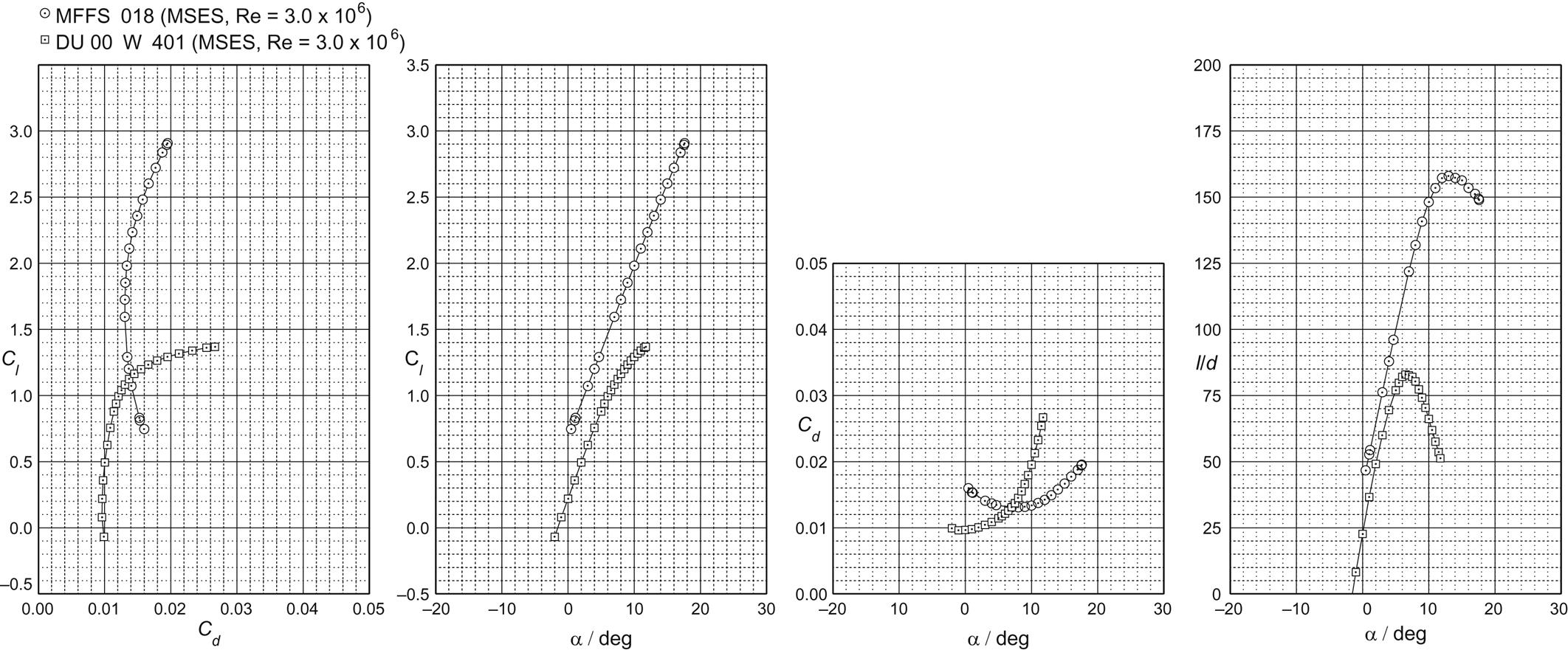
The aerodynamic performance of the MFFS-018 and DU 00-W-401 airfoils are compared in Fig. 11.6. These comparison data are from MSES at Re=3.0×10⁶. As determined by MSES, the DU 00-W-401 airfoil at Re=3.0×10⁶ has a Cl/Cd,max of 82.9 at Cl=1.04 and α=6.5 degrees. The MFFS-018 configuration shows a lift-to-drag ratio of Cl/Cd,max=158.0 at a lift coefficient of Cl=2.34, which is a slightly greater lift-to-drag ratio than a single-flapped MFS configuration at a lower lift coefficient [1]. The MFFS-018 configuration appears to be well-suited for higher Cl values because it demonstrates the highest Cl/Cd,max of all the configurations analyzed in reference [1], but offers a Cl/Cd at Cl=1.7 that is lower than single-flapped multielement arrangements. As shown in Fig. 11.6, the drop off of Cl/Cd beyond Cl/Cd,max was gentler than that of the DU 00-W-401 airfoil in the MSES simulations.
The MFFS airfoil arrangement was selected over a single-flapped configuration for a number of its benefits. The first benefit is that its double-slotted flap arrangement allows for a high degree of aerodynamic tunability to achieve high Cl/Cd ratios at specific Cl values. These specific Cl values would allow for operation at an optimal axial induction factor over a larger portion of the blade. Additionally, an increased separation between the two elements would yield an aerodynamic benefit because the strut and main element act in a biplane-like manner. An increase in spar cap separation is desirable because it offers increased structural benefits, including a stronger structure and decreased tip deflections [11–13]. By offering separate airfoil fairings for the upper and lower spar caps, this well-separated multielement arrangement is able to solve the problem of competing aerodynamic and structural requirements.
The design of the multielement airfoil families was an iterative process between airfoil and blade design. Using the MFF or MFFS, DU 91-W2-250, DU 00-W-212, and DU 96-W-180 airfoils, an initial multielement blade was designed. The Cl distribution used to design the blade was chosen to produce a smooth chord distribution with no jagged edges or protrusions. This Cl distribution, along with the resulting chord, twist, and Reynolds number results from the PROPID [20] propeller analysis were used to determine the desired airfoil performance requirements for the multielement airfoils. The new airfoils would then be used in PROPID to modify the blade design. Results from PROPID were then used to define the new performance requirements for modifying the multielement airfoils. This process would be iterated upon until the airfoil and blade designs converged. Figs. 11.7 and 11.8 present the resulting MFS and MFFS multielement airfoil families, respectively, with correct twist and chord lengths normalized to the DU 91-W2-250.
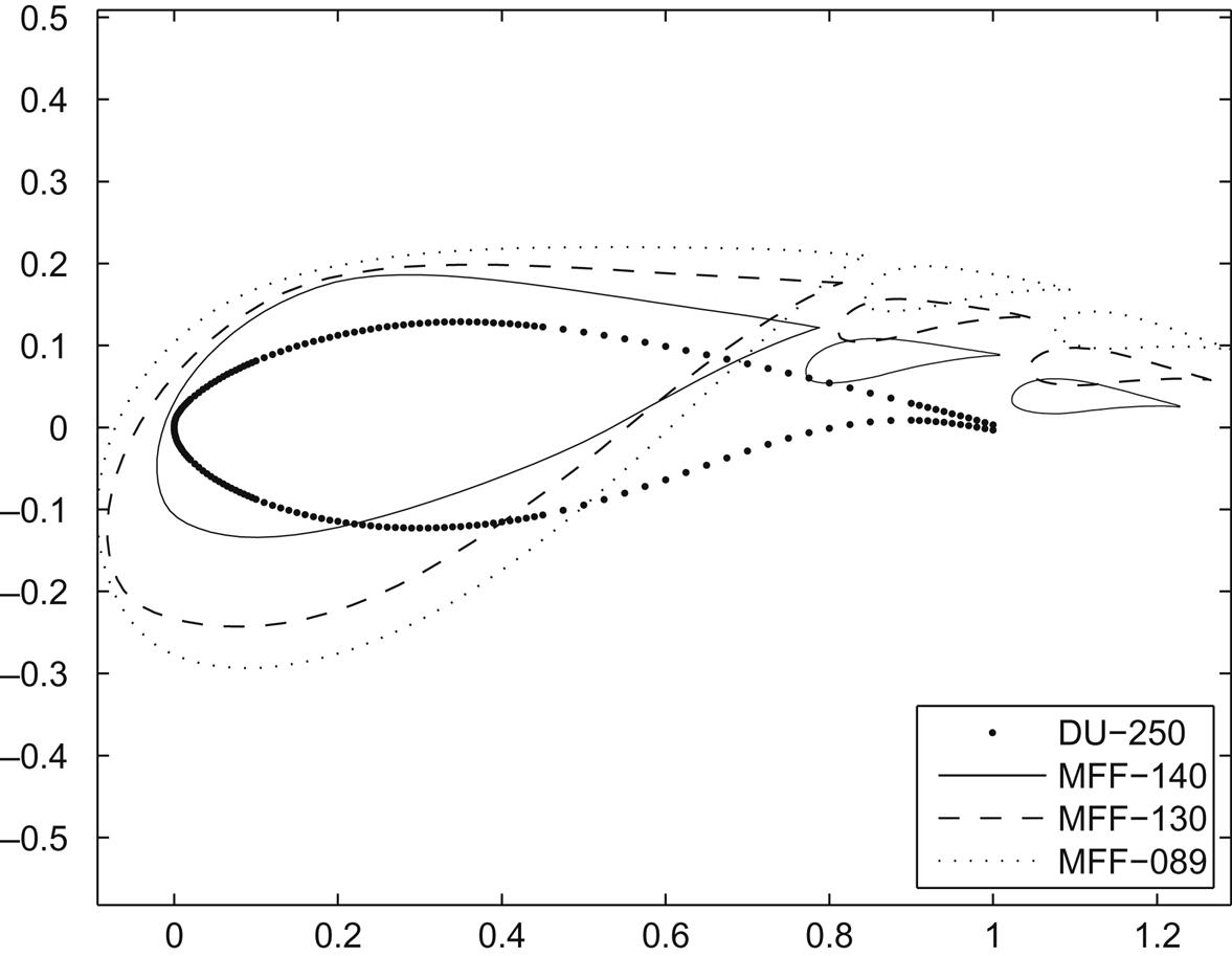

While Figs. 11.7 and 11.8 present a cross-sectional view of the candidate wind turbine blades, a conceptual drawing of what a multielement wind turbine blade based on the MFFS family of airfoils would look like is presented in Fig. 11.9 for clarification. The MFF-089 and MFFS-026 multielement blade root airfoils were designed in MSES for wind tunnel testing [17] in the University of Illinois subsonic low-turbulence wind tunnel at Reynolds numbers between 0.75×10⁶ and 1×10⁶. For ease of manufacturing, the two flap elements of the MFF-089 are identical to the two flap elements of the MFFS-026 [17]. The MFF-130 multielement airfoil was designed to produce a high Cl/Cd ratio at Cl=1.3 and Re=10×106. The MFF-140 was designed for Cl=1.1 at Re=11×106. The MFFS-138 was designed for a high Cl/Cd at Cl=1.5 and Re=9.5×10⁶ while the MFFS-140 was designed for Cl=1.25 at Re=11×106.

All airfoil data presented herein were from the MSES flow solver. This program is known to especially overpredict the lift performance of thick airfoils such as the DU and MFF airfoils used for the inboard section of the baseline blade [25,26]. This characteristic was observed when the MSES predictions for the DU airfoils and the MFF-089 multielement airfoil arrangement were compared to unpublished wind tunnel results and published CFD results [16]. Because of the overpredicted lift performance of thick airfoils, the performance of a baseline conventional blade with thick airfoils would be overpredicted, and thus the gains achievable through the use of multielement airfoils on the inboard sections of a wind turbine blade would not be accurately modeled. Even with this overprediction of the baseline performance, PROPID simulations of a three-bladed 10 MW wind turbine with a diameter of 176 m (577 ft.) showed increases in GAEP of approximately 1%, with larger increases existing at lower wind speeds. This candidate wind turbine was designed to operate at a tip-speed ratio of 8.7 and at 9.8 revolutions per minute (RPM). The maximum blade chord of the baseline was capped at 4.9 m (16 ft). Based on the size of the concept wind turbine, it would likely be of the direct-drive variety [8] and would most probably be located offshore.
To conduct PROPID simulations, the desired Cl distribution for the blade design was chosen to create a blade with a typical chord distribution. The locations of the airfoils along the span of the blade were chosen to maximize the lift-to-drag ratio along the blade and to ensure a smooth twist and thickness distribution. To show the benefits of using the MFF family of airfoils, a blade was designed and analyzed using PROPID. The baseline 10 MW blade was used as a starting point, and the thick DU airfoils were replaced by the MFF airfoils. Only the inboard section of the blade was modified, so that from the DU 91-W2-250 airfoil (located at the 47% blade station) to the tip, the baseline and multielement blade designs are the same.
Aerodynamically the MFF and MFFS multielement airfoil configurations are superior to typical thick root airfoil sections of modern megawatt-scale wind turbines in many respects. When compared with a traditional section, these multielement configurations are capable of producing much higher maximum lift coefficients, with Cl values of up to 3.0 compared to the Cl,max=1.04 for the 40.1% thick DU 00-W-401 airfoil. Moreover, these multielement airfoil configurations produce much higher lift-to-drag ratios on account of both higher lift and much lower drag, with increases between 40% and 90% in Cl/Cd,max over the DU 00-W-401. At Cl=1.7, the MFS-104 multielement configuration produced the greatest percent gain in Cl/Cd with a 60.7% increase over the DU 00-W-401 airfoil. The value of Cl=1.7 was selected as a realistic value for the inboard section of a wind turbine blade; significantly larger Cl values would greatly exceed current blade structural limits. As demonstrated by the SMFS case of references [1,27–29], the addition of a slat results in an increase in the Cl/Cd,max value of a multielement arrangement, but this comes at the cost of a sharper drop off in Cl/Cd above Cl/Cd,max when compared to a nonslatted multielement arrangement. By moving the strut element farther below the main and flap elements, the Cl/Cd,max value may be increased as a larger amount of lift is generated by the main element.
Based on the MSES results and preliminary PROPID results, the use of multielement airfoils is very promising. Multielement airfoils allow the lift coefficient and lift-to-drag ratios of the inboard section of a wind turbine blade to be increased. This results in a number of aerodynamic benefits. The axial induction factor can be increased to be closer to the ideal Betz value of one-third [3] near the inboard portion of a wind turbine blade. Additionally, the increased lift near the hub will allow for a larger tangential force coefficient Ct [2], which, in turn, will provide the turbine with increased torque from the root section and will create the potential for a lower cut-in wind speed and increased power output at low wind speeds. This reduction of the cut-in wind speed will help to increase the capacity factor, and may allow new locations to be opened up for wind turbines that may not be economically viable with conventional single-element wind turbine blades.
11.5 Other Multielement Wind Turbine Research
A number of studies have been performed into the potential benefits of adding slats to the inboard sections of wind turbine blades [27–31]. These studies were performed because due to the large thickness of the blade root as required by structural constraints, the aerodynamically suboptimal airfoils [1] produce loadings on the blade root section that are significantly lower than those corresponding to the maximum energy capture [28]. Gaunaa et al. [28] performed computational investigations on rotor slats for the regime defined by 0.1>r/R>0.3 for the Light Rotor baseline 10 MW reference wind turbine rotor, where r/R is the radial location on the rotor (r) normalized by the rotor radius (R). Using 3D CFD, a significant modification of the flow field of the inner rotor region was observed. These changes caused by the addition of slats to the inboard region of the rotor were calculated to increase the CP by 1% with a corresponding CT increase of 2% [28].
In an earlier work, Gaunaa et al. [29] articulated that the material costs, stand still loads, and maximum chord length as determined by transportation requirements have caused the center part of utility-scale wind turbine blades to be loaded at significantly less than the optimal power production loading condition. Simply increasing the chord length near the hub would help resolve these issues, but issues of cost, transportation, and extreme structural loads limit this idea to academic studies. Thus the motivation for investigating the retrofit of slats to existing wind turbine blades was created. Using a Blade Element Momentum (BEM) based approach to evaluate the 2D CFD-optimized slat designs, it was estimated that the retrofit of slats to the root section of a candidate 10 MW turbine would likely yield a greater than 1% increase in the annual energy production [29].
In general slats were investigated as additions to a previously designed rotor because the design problem is simplified due to the involvement of fewer degrees of freedom [29]. A later study by Jaume [30] investigated both a slat superimposed upon, and integrated into the geometry of, the DU 91-W2-250 airfoil developed by the Delft University of Technology [15]. It should be noted that this airfoil is located at r/R=43% and is 25% thick. By adding a leading edge slat, the angle of attack range over which the airfoil performed efficiently was increased. Additionally, the maximum lift coefficient was increased by 64.8% and the critical angle of attack was increased by 9 degrees [15]. A downside to the addition of the slat is that the drag is greatly increased as low angles of attack. Jaume et al. [15] report that the optimization procedure used to design a slat for the DU 91-W2-250 will be applied to the five remaining airfoils of their reference blade in order to determine the preferred spanwise extent of retrofittable slats. In regard to thicker airfoils, the addition of a slat, based on the NACA 22 airfoil, to the 30% thick DU-97-W-300 airfoil was studied by Eisele and Pechlivanoglou [31]. Zahle et al. [27] used 2D CFD to optimize the shape of a slat for a 40% thick wind turbine airfoil [27].
While a large number of academic studies have been discussed, two current industry studies are of note. GE has researched placing a hemispherical dome over the inner parts of a wind turbine in its Energy Capture Optimization by Revolutionary Onboard Turbine Reshape (ECO ROTR) and has shown that this concept has improved the performance of the wind turbine. This dome concept was tested in 2012 in the Gust wind tunnel at the University of Stuttgart in Germany. The results were promising enough that starting in 2013, a full-scale test program was initiated. A geodesic dome 20 m in diameter weighing 20 tonnes was installed on a 1.7 MW 100 m diameter space frame tower (SFT) turbine in Tehachapi, California. On May 25, 2015, the dome was installed on the wind turbine, and it was reported that the turbine performance would be evaluated over a 4-month period.
The second industry study of note is the multirotor concept introduced by Vestas in April 2016. Vestas claims that by installing four smaller rotors on a main tower, the scaling rules of wind turbines can be challenged; they report that transport and installation challenges can be mitigated through this novel concept. Work on this project is being conducted in cooperation with the Technical University of Denmark as a research partner, and a concept demonstrator is being installed at the Risø site near Roskilde, Denmark.
11.6 Discussion
Multielement airfoils for wind turbines hold great promise. In addition to increasing the aerodynamic efficiency of wind turbines, they also show strong promise for resolving transportation issues associated with large blades. In regard to the structural considerations, the use of multielement airfoil configurations will allow for the currently competing aerodynamic and structural requirements to now be aligned. Whereas with current thick single-element airfoils, aerodynamic requirements push for a thinner airfoil and structural requirements push for a thicker airfoils, with the use of multielement airfoils with a main and strut element, both aerodynamic and structural requirements call for an increased vertical separation between the elements. While the join location where the wind turbine blade would transition from a multielement airfoil to a single element will add some weight, weight will be saved at the root section through the improved structural arrangement. Additionally, this heavy transition section will bring with it the ability to assemble the blades onsite in segments, which will ease transportation concerns.
Focusing on the aerodynamic aspects of the use of multielement airfoils on wind turbines, the potential for better start-up performance exists due to a higher Ct from higher lift airfoils as well as increased blade efficiency from more closely matched ideal operating conditions along the blade. Altogether these aerodynamic advantages are expected to increase the efficiency of the wind turbines through both increased energy production and reductions in blade material and mass, with an ultimate result of a lower cost of energy. Finally these multielement configurations demonstrated the desirable characteristic of a gentler drop off in Cl/Cd beyond Cl/Cd,max when compared to the DU 00-W-401 airfoil.
By replacing the thick root airfoils with a multielement airfoil arrangement over the inboard 47% blade span on a wind turbine, the annual energy production of a 10 MW scale turbine can be increased by at least 1%. This increase is due to the larger Cl/Cd ratios attainable by the multielement arrangements and is only a minimum value due to the overprediction of the thick airfoil performance values. The blades with a multielement root also had larger Cl values inboard allowing for a more optimal axial induction factor closer to the hub. This increased inboard lift is expected to provide more torque at the root which in turn will result in a lower cut-in wind speed. Multielement wind turbine blades can be designed to have at least the same blade thickness near the hub as the conventional baseline design while maintaining improved performance. The use of a well-separated blade design for the root section introduced both the ability to increase the spar cap separation to create a stronger structure and the potential for natural disconnect points to allow for simplified transportation of large blades to the turbine sites. The MFFS design was successfully designed to be thicker than the baseline, both in terms of absolute thickness and t/c ratio, and a thicker blade allows for a stronger spar structure.
Acknowledgments
Support for some of this research was provided by GE Energy and the UIUC Department of Aerospace Engineering. Dr. Robert Deters from the Department of Engineering Sciences at Embry-Riddle Aeronautical University conducted the PROPID wind turbine simulations mentioned in this chapter.