
Magnetic Materials
AG Clegg, MSC, PHD, University of Sunderland (Sections 8.1 and 8.7)
P Beckley, BSc, PhD, DSC, CEng, FIEE, FIM, FInstP, European Electrical Steels, Newport (Sections 8.2 and 8.3)
EC Snelling, BSc(Eng), CEng, FIEE, Formerly of Philips Research Laboratories, Redhill (Section 8.4)
RV Major, MSc, PhD, FInstP, MIM, CEng, Formerly of Carpenter Technology (UK) Ltd, Crawley (Sections 8.5 and 8.6)
8.1 Ferromagnetics
The choice of materials having ferromagnetic properties is very wide. Other than iron, a number of elements such as nickel and cobalt as well as some manganese alloys are ferromagnetic.
It has so far been impossible to obtain absolutely pure iron, in the true sense, even under laboratory conditions; but iron in which the impurities have been reduced to a mere trace has been found to have a maximum relative permeability of 50 000 and a very low hysteresis loss. However, even if it were possible to produce an iron of this degree of purity commercially, its low resistivity would be a disadvantage with alternating fluxes because of eddy currents.
The common impurities in iron are carbon, manganese, silicon, copper, sulphur, phosphorus and oxygen and the general effect of these impurities is to reduce the permeability and to increase the hysteresis loss. Sulphur, phosphorus and oxygen are particularly injurious and the presence of these has to be reduced to the lowest possible level. The presence of small amounts of silicon up to about 5% is beneficial. Small amounts of manganese are not injurious, but when the manganese content reaches 12%, a particularly non-magnetic steel is obtained. To neutralise the effect of impurities and to confer special properties, iron is alloyed with other elements, of which the following are the most important: nickel, cobalt, silicon, chromium, tungsten, molybdenum and vanadium.
The magnetic properties of ferromagnetic materials depend not only on their chemical composition, but also on the mechanical working and heat treatment they have undergone. For practical purposes magnetic materials fall into two main groups, high permeability or soft magnetic materials and permanent magnets or hard magnetic materials.
There are a number of groups of soft magnetic materials including soft iron, mild steel, silicon steels, nickel irons and ferrites. In static d.c. applications mild steel is the main bulk material, but where better properties are required with greater magnetic permeability, soft iron is used. Silicon steel is the bulk material for low frequency alternating fields and the nickel irons are used for more specialised applications with the soft ferrites being used at higher frequencies because of their higher resistivity.
There are four main classes of permanent magnet materials: steels, Alnicos, hard ferrites (also called ceramics) and rare earth alloys. Of these the steels are almost obsolete because of their inferior properties and the ferrites have gradually taken over from Alnico as the main bulk material, mainly due to their cost advantage. The rare earth alloys SmCo and NdFeB because of their superior properties have created new interest and have found a great many new applications. They have enabled considerable weight savings to be made in many instances.
8.2 Electrical steels including silicon steels
Electrical steels form a class of sheet material used for the flux-carrying cores of transformers, motors, generators, solenoids and other electromechanical devices. Almost always alternating magnetisation is employed and the material is designed to keep power losses due to eddy currents and magnetic hysteresis to a minimum.
8.2.1.1 Eddy current losses
Minimisation of eddy currents is achieved by using thin laminations. The e.m.f. generated in a lamination is proportional to the cross-section of the lamination for a given peak magnetic flux density and frequency; while the path length (and resistance) varies only slightly for a given lamination width, so that lamination of the core reduces the V/R ratio for the eddy currents (see Figure 8.1).
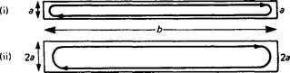
The current is proportional to (area of cross-section)/(path length).
Power rises as I2R so that loss per unit volume rises rapidly as the sheet thickness increases. By increasing the resistivity of the steel, eddy currents may be further restrained and this is usually done by adding silicon as an alloying element. Silicon additions range from zero up to some 3.25%.
Over this range the resistivity may vary from about 12 to about 48–50 Ω-m × 10−8.
The addition of silicon has the effect of reducing the saturation flux density of the steel so that a larger core cross-sectional area is needed to carry a given magnetic flux.
8.2.1.2 Hysteresis losses
Magnetic hysteresis is another source of power loss which can be reduced by the addition of silicon as an alloying element. While the area of the very low frequency B—H loop is often taken as a measure of hysteresis loss, effects which impede magnetic domain wall motion alter with frequency. At 50 or 60 Hz the overall loss mechanism is a complex mixture of macro eddy currents relating to lamination thickness, micro eddy currents associated with the movement of the internal domain walls and energy dissipative hysteretical effects due to impediments to free domain wall motion. Such impediments may be non-metallic inclusions, grain boundaries or regions of stress within the crystal lattice of the material.
Table 8.1 gives an outline of the principal types of electrical steel produced in the UK, and some of their properties and applications.
Table 8.1
Selection of electrical steel grades produced by Cogent Power Ltd—typical properties
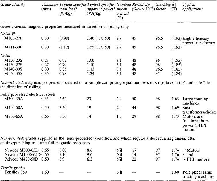
*At B = 1.5 T, 50 Hz. Values in parentheses are for ωB = 1.7 T and 50 Hz.
†At ωH = 5000 A/m. Values in parentheses are for ωH = 1000 A/m.
As the percentage of added silicon increases, the steel becomes more difficult and expensive to process. Thinner material is more costly because it requires more rolling and processing. The key points of a material specification are given in Table 8.1.
Primary grading is by power loss in watts per kilogram at a peak magnetic flux density of 1.5 or 1.7 T and 50 Hz (60 Hz in the USA).
8.2.2 Ancillary properties
8.2.2.1 Specific apparent power
Specific apparent power (in volt-amperes per kilogram) gives an indication of the r.m.s. ampere-turns which must be available to maintain a given state of alternating magnetisation, e.g. a peak value of 1.5 T at a specified frequency. Most of the current drawn is 90° out of phase with the supply voltage and so is non-dissipative, but copper or aluminium windings of sufficient cross-section must be used to keep copper losses low in the face of the current demanded.
8.2.2.2 Permeability
There are many varieties of permeability, but for electrical steels those of most interest are, ![]() , and
, and ![]() that is the peak value of magnetic flux density attained under the influence of an applied field of 1000, 2500, 5000 and 10000 A/m, respectively.
that is the peak value of magnetic flux density attained under the influence of an applied field of 1000, 2500, 5000 and 10000 A/m, respectively.
8.2.2.3 Surface insulation resistance
This is a measure of the quality of the surface insulating coating (expressed in ohm-metres squared) used to restrain the flow of current between laminations.
8.2.2.4 Stacking factor
This is the ratio of the height of a stack of laminations calculated from the volume of metal present to the measured height of the stack of laminations under a specified clamping pressure, for the same cross-sectional area of material. The stacking factor is expressed as a percentage and typical figures range from 96% to 98%.
8.2.3 Chemistry and production
Electrical steels are produced by a complex process of casting, hot rolling, cold rolling and heat treatment. The end product must be very low in carbon and sulphur and free from non-metallic inclusions—that is metallurgically very ‘clean’.
The magnetic properties are much improved if the grain size of the metal can be enlarged, up to a maximum of some 1 cm diameter for some grades and considerable metallurgical skill is employed to procure an end product that is chemically appropriate, metallurgically clean and of optimum grain size.
8.2.4 Physical form
Electrical steels are normally sold in coil form in coil weights up to several tonnes and widths up to 1 m wide, or in sheets cut to lengths of up to 3 m. Thickness normally ranges from 0.23 mm up to 0.65 mm (1.6 mm if high tensile grades are included). Strip can be supplied fully finished in a state of final anneal and carrying an insulating coating or semi-finished so that users can cut or punch the material and apply a final heat treatment and perhaps coating before building into a core. Electrical steels are susceptible to stress and mechanical damage so they must be handled with care and, if appropriate, re-annealed to recover properties damaged by stress. Appropriate heat treatments are normally an anneal at 800°C in a neutral atmosphere (non-oxidising) or a decarburising anneal at some 900°C in wet hydrogen.
When supplied as slit, narrow strip steel can be used to wind ‘clockspring’ cores directly without need for punching.
8.2.5 Coatings
The insulative coatings applied to electrical steels fall into two main classes: organic and inorganic. Organic coatings are inexpensive but cannot be used if further annealing is to be applied to the steel.
Inorganic coatings are resistant to annealing and some may be formed during the processing of the steel for the development of its magnetic properties.
Coatings having both organic and inorganic components can be used, so that the organic component which aids punching may disappear on anneal but a useful inorganic residual coating remains.
8.2.6 Grain orientation
The grains in electrical steel of the so-called ‘non-oriented’ type are, for the most part, randomly arranged so that the magnetic properties of sheet are broadly isotropic. This is convenient for many applications where flux must flow in varying directions in the steel.
However, if the grains are specially oriented so that an easy direction of magnetisation of the crystal lies along one direction of the sheet (normally the production rolling direction) then the magnetic properties in this direction are much enhanced at the expense of those at other angles to the rolling direction.
This, so-called, ‘grain orientation’ requires a costly and complex regime of rolling and heat treatments and the high-temperature anneal stage of production produces a glass film on the surface of the steel which acts not only as an insulating coating but also as a further means of enhancing magnetic properties. When steel bearing a glass coating cools from a high temperature the steel contracts more than the glass so that at room temperature the glass coating is holding the steel in a state of tension. This tension improves the magnetic properties of the steel, so that the material at its best functions as a composite system of a precisely grain oriented steel substrate held in a state of beneficial tension by a very thin (some 1–2 μm) layer of glass which also acts as an interlaminar insulant. A final phosphate coating is usually applied to complete the insulation and tensioning process.
8.2.7 Test methods
The test methods for electrical steels are fully described in BSEN 60404–2: 1998 and BSEN 10280: 2001 and in IEC standards 60404–2 and 60404–3. These tests seek to simulate the service conditions of electrical steels.
One of the best-known test methods is the Epstein test in which a set of strips of steel each 30.5 cm long and 3 cm wide are arranged in four limbs with double lapped corners to form a hollow square. Four double sets of windings enclose the strips and these are energised to produce a situation analogous to that in a small transformer at operating levels of magnetic flux density and under ‘no load’ conditions. Careful measurements of magnetic properties are carried out using a precision wattmeter and ancillary instrumentation.
There is a growing trend towards the use of single plates some 50 cm square for tests, and increasing use of such plate tests will reduce the labour involved in the lengthy Epstein test.
Cogent Power Ltd produces specialist test equipment for the measurement and quality control of electrical steel as do some instrument makers.
Steel producers offer a customer advisory service which in the case of Cogent Power Ltd is offered as well as the services of their Standards Laboratory which holds United Kingdom Accreditation Service (MKAS) approval for power loss testing at Newport in South Wales.
8.2.8 Various
Electrical steels cover a wide range of applications, some are made to have especially high strength for use where heavy mechanical loads arise. Some are of specially precise grain orientation where very low power loss and the highest permeability are vital. Some are simple but inexpensive for use in applications where cost and ease of manufacture of the final article may be paramount.
Electrical steels used inside nuclear reactors must behave well under conditions of high temperature and neutron flux.
Wherever alternating magnetic fields must be managed efficiently and economically, electrical steels of one variety or another can assist.
8.3 Soft irons and relay steels
The primary aim of soft irons is to be a close approximation to pure iron. Efforts are made to keep contaminant elements to a low level—particularly carbon and sulphur.
Carbon levels of 0.005% are advantageous, but expensive to produce, and material of intermediate quality can be obtained with carbon ranging from this low level up towards 0.05% and higher. At 0.1% carbon the material becomes a common ‘mild steel’ and while it can still be processed to have useful magnetic properties it is no longer a specialist material. Sulphur levels are kept as low as possible and <0.01% is a good aim.
8.3.2 Applications
Soft iron (or ‘relay steel’ as it is often called) is used largely for the magnetic circuits of electromechanical relays and solenoids, for the pole pieces of d.c. magnets and parts of the magnetic circuits of small generators. Quite a considerable amount of soft iron is used in the construction of particle accelerators for nuclear research where huge magnets are required to guide accelerated particle beams.
8.3.4 Metallurgical state
To achieve the best magnetic properties the material should be free from non-magnetic inclusions, have large grains and be free from internal stress.
8.3.5 Magnetic characteristics
The primary grading property of soft iron is coercive force—that is the magnitude of reverse field required to demagnetise the steel fully after a previous magnetisation to a specified value of magnetic flux density. This is shown as the distance PQ on the H axis of the B—H loop in Figure 8.2.
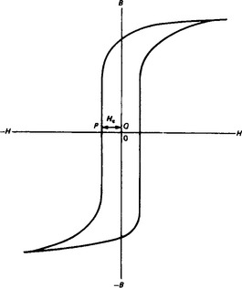
Figure 8.2
Coercive force is important as it indicates the amount of hysteresis which a material exhibits.
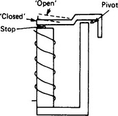
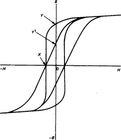
In an electromechanical relay (Figure 8.3) the magnetic circuit has quite a large air gap in it when the relay armature is in the relaxed ‘open’ state. When ‘closed’ the air gap is less but still of finite size (often set by a non-magnetic stop pip). It is well known that the magnetic reluctance of the air gap in a magnetic circuit produces ‘shearing’ of the B—H loop of the circuit material (see Figure 8.4). The coercive point X stays the same under loop shear, but the remanent point Y moves to Y′. It is apparent that material having a ‘thin’ loop with a small Hc will show a greater fall in remanence for a similar amount of ‘shear’ than will a material of high Hc and having a ‘fat’ loop. For this reason coercive force is used as a quality guide for material which ideally should have as low a hysteresis as possible.
Besides coercive force, permeability is important. Depending on the application the low-, mid- or high-field permeability may be important and strict specifications may be placed on the magnetic induction (tesla) achieved for a given applied magnetic field strength.
8.3.6 Grades and specifications
BS6404:8.10: 1994 is the UK Standard for grades of soft iron. Traditionally, a chemical specification has been used for the supply of relay steels and soft iron, but this can lead to wide variations of magnetic properties within a batch which meets the chemical specification.
Typically, steel is offered to a magnetic specification within five coercive force grades:
(There is still much use made of the CGS unit, the oersted, (Oe) for soft iron grading). Material supplied to a magnetic guarantee is much more satisfactory to the relay designer and quality control engineer.
8.3.7 Heat treatment
It is important that iron should be in a fully annealed stress-free state in its final form in a magnetic circuit. Most material is punched, sheared, upset or machined in one way or another during fabrication, all of which induces high stress. An appropriate heat treatment of a piece—part will allow the material to give the best performance in service.
Optimum heat treatments are best worked out in conjunction with the steel supplier. Broadly, a 950°C anneal in a neutral atmosphere followed by a slow cool over several hours is satisfactory.
Where material is fairly thin (up to 1 or 2 mm) the final heat treatment can, with advantage be decarburising so that lowest coercive force is obtained as residual carbon is removed. Decarburising anneals employ furnace atmospheres of wet hydrogen and, again, require specialist advice.
8.3.8 Ageing
A final anneal takes residual carbon into solution and some of this may precipitate over a period of years leading to increases in coercive force as domain wall motion becomes impeded by carbon precipitates. Ageing may be minimised by keeping carbon content low and by use of special stabilising additions to the steel. When necessary, modern irons can be made ageing-free.
8.3.9 Test methods
British Standard BSEN 6404–4: 1997, now being amended, deals with test methods appropriate to relay steels. It covers the more lengthy procedures in which a welded ring is used as sample (or stamped rings from sheet), or the use of a d.c. permeameter with flux closure yokes. BS 6404: Part 7 (1986) gives details of the Vibrating Coil Magnetometer with which it is possible to obtain a coercive force reading in a few seconds. This is a very simple procedure compared with the more lengthy permeametric methods which require ballistic galvanometers, etc.
Cogent Power Ltd have pioneered the production of the Vibrating Coil Magnetometer for sale to industry in conjunction with the National Physical Laboratory.
IEC Standards 60404–4 and 60404–7 are equivalent to BS 6404 Part 4 and BS 6404 Part 7 respectively. Study of the UK and IEC Test Standards is of the greatest assistance in understanding how to grade soft irons for quality.
8.3.10 Other applications
Where relays must operate at the highest speeds it is necessary to raise the electrical resistivity of the magnetic circuit. This is necessary so that flux can penetrate the core iron rapidly. A low electrical resistivity gives rise to very vigorous induced eddy currents which oppose flux penetration to the centre of the material. The use of lamination is not often suitable so resistivity can best be raised by the addition of silicon, up to some 3% as required. This produces a fourfold increase in resistivity.
Thin iron is often used for screening. This may be applied to cables to reject outside interference or to load them inductively. Whole areas may be screened with iron enclosures where steady field or field-free conditions are essential. For this purpose screens consisting of layers of iron and air are the most effective.
8.4 Ferrites
In the context of electromagnetism, ferrites may be defined as magnetic materials consisting of compounds of metallic oxides and containing ferric ions as the main constituent. They usually have the structure of polycrystalline ceramic materials, but for some special applications the single crystal form is used. Ferrites are used in a wide variety of applications in electronic and communication engineering.
In the crystal lattice of ferrites the metal ions are separated by oxygen ions and this results in high electrical resistivities which suppress eddy currents and their usually undesirable effects. Another important consequence of the presence of oxygen ions is that the magnetic moments of the metal ions on the two constituent sublattices have anti-parallel alignment so that the net available magnetisation is the difference between the magnetisations of the sublattices (ferrimagnetism). This, together with the dilution due to the presence of the non-magnetic oxygen ions, inherently limits the saturation flux density of ferrite materials to about 0.4–0.6 T (compared to about 2 T for some magnetic alloys).
The usual manufacturing process consists of the following steps; mixing of raw materials (oxides, carbonates, etc.) in the required proportions, calcining at about 1000°C, crushing, milling, powder granulation, forming to the required shape by pressing the powder in a die or by extrusion, and finally sintering the piece parts at about 1250°C for up to 12 h in a controlled atmosphere. During sintering, crystallites of the required formulation are formed by solid-state reaction and this process is accompanied by a shrinkage of linear dimensions of between 10 and 25%. The product is a black brittle ceramic piece part having a density of about 4800 kg/m3. Any subsequent shaping operations, such as pole face finishing, have to be done by grinding (and sometimes lapping).
Ferrites may be broadly divided into the magnetically soft category, those having high permeability and low losses, and the magnetically hard category, those having permanent-magnet properties. The hard ferrites are described later.
8.4.1 Magnetically soft ferrites
Magnetically soft ferrites have the cubic crystal structure of the mineral spinel. In ferrites, this structure is characterised by a very low magnetocrystalline anisotropy which results in the ferrite having a very low coercivity, high permeability and low magnetic power losses at frequencies extending up to 300 MHz, depending on composition. The chemical formulation is represented by MeFe2O4 where Me is most commonly a combination of manganese and zinc with some ferrous iron (abbreviated to MnZn ferrite), or nickel and zinc (NiZn ferrite). Minor constituents (additives or substitutions) are often included in order to enhance particular properties.
Ferrites are usually manufactured in the form of specific core shapes such as rings and a wide variety of pot-, E-, and U-shaped cores. Except for rings, the complete cores are usually assembled from pairs of half cores, the mating surfaces having been ground flat and sometimes lapped to ensure a low-reluctance joint. Where the application requires the core to contain an air gap in order to modify the properties of the wound assembly, one of the pole faces in the magnetic circuit is ground back by a specific amount during manufacture.
8.4.1.1 Properties
The properties of a ferrite material are strongly influenced by the composition, the presence of minor constituents and the details of the manufacturing process. For example, increasing the proportion of zinc lowers the Curie point and affects the saturation flux density. In MnZn ferrites the presence of a small proportion of the iron in divalent form critically controls the temperature coefficient of the permeability and influences the bulk resistivity and the magnetic losses. By varying these and other factors, a wide range of ferrite grades can be made, each specifically matched to a particular application. Typically a manufacturer’s range of ferrite grades may extend to over fifty different specifications.
All ferrites exhibit a ferrimagnetic (or spin) resonance frequency at which the permeability falls to a very low value and the magnetic losses peak. For soft ferrites in general, the product of the low frequency initial permeability and the ferrimagnetic resonance frequency is approximately a constant (Snoek’s law). So a high-permeability ferrite has a low cut-off frequency; where low losses are required at higher frequencies, ferrites having lower permeabilities must be used, see Figure 8.5
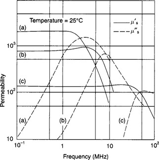
Figure 8.5 The inductive component of the permeability, μ′s, and the corresponding loss component, μ″s, as functions of frequency for three typical ferrites. (a) is an MnZn ferrite having an initial permeability of 2000 and intended for high performance inductors at frequencies up to about 0.3 MHz, (b) is an MnZn ferrite having a permeability of about 700 and is intended for inductors operating at frequencies of 0.3–0.7 MHz and (c) is an NiZn ferrite with a permeability of 130, applicable to inductors intended for the low MHz band
Generally, the MnZn ferrites have the higher permeabilities and lower losses in the frequency range up to about 2 MHz; their bulk resistivities lie between about 0.05 and 20 Ωm. The NiZn ferrites have lower permeabilities (dependent on the Ni/Zn ratio) and higher losses (relative to the MnZn ferrites) below about 2 MHz. However, they maintain their useful properties to much higher frequencies. Their resistivities are about three orders of magnitude higher than those for MnZn ferrites and so are virtually free of eddy current effects.
The initial permeability, μi, is the permeability at very low field strengths. High values of μi are desirable in principle, but Snoek’s law dictates that the optimum initial permeability falls as the frequency characterising the application rises. If an air gap is inserted in the magnetic circuit of a core, the permeability apparent to a winding on that core is reduced to the effective permeability, μe. At the low flux densities appropriate to signal applications, the magnetic loss in ferrites is expressed in terms of a loss factor defined as the tangent of the loss angle divided by the initial permeability, (tan δ)/μi. The loss tangent of a gapped core equals the loss factor multiplied by the effective permeability. In many applications the flux density is low enough for the hysteresis loss to be negligible. The main loss is then represented by the residual loss. This is low over the lower frequency region but rises rapidly as the frequency of ferrimagnetic resonance is approached. Figure 8.6 shows the residual loss factor as a function of frequency for three typical ferrites: (i) is a low loss MnZn ferrite, (ii) is a high permeability MnZn ferrite intended for signal transformers, and (iv) is an NiZn ferrite with a permeability of about 130. Other properties of these typical ferrites are listed in Table 8.2
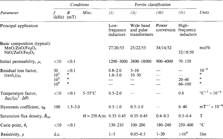
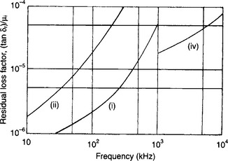
Figure 8.6 Typical residual loss factors as functions of frequency. (For material classifications see Table 8.2)
The temperature dependence of the initial permeability is important for inductor applications. As a material property it is usually expressed as a temperature factor Δμi/(μi2 Δθ), where θ is the temperature. If a core is gapped so that it has an effective permeability, μe. then the temperature coefficient of effective permeability (and therefore of the inductance of a winding on the gapped core) is μe times the temperature factor. So the temperature coefficient of inductance can be determined by the choice of the gap length. For an inductor used in filter applications, the negative temperature coefficient of the tuning capacitor can thus be compensated to achieve very high combined temperature stability.
In applications involving MnZn ferrites, the finite conductivity of the material gives rise to some eddy-current loss in the core. This loss depends on the size and shape of the core and, although small in relation to the total core loss at low frequencies, it can become significant at frequencies above about 50 kHz, depending on the ferrite resistivity and the size of the core. The low-amplitude hysteresis loss in a ferrite is expressed in terms of a coefficient, ηB, such that the hysteresis loss factor ![]() , where
, where ![]() is the peak flux density. The hysteresis coefficient of a ferrite determines the Total Harmonic Distortion (THD) generated by a core made in that material, e.g. for a pulse transformer. In modern digital networks THD is a critical parameter in that it can cause bit errors. Special MnZn ferrites with high permeability and very low hysteresis loss have extremely low THD levels and are to be recommended for such applications.
is the peak flux density. The hysteresis coefficient of a ferrite determines the Total Harmonic Distortion (THD) generated by a core made in that material, e.g. for a pulse transformer. In modern digital networks THD is a critical parameter in that it can cause bit errors. Special MnZn ferrites with high permeability and very low hysteresis loss have extremely low THD levels and are to be recommended for such applications.
In power applications the important material property is the power loss per unit volume, i.e. the power loss (volume) density. The principal component of this is the magnetic loss which is defined as the loss due to all causes other than the eddy currents generated in the bulk of the core. The magnetic loss (volume) density ![]() , where k is the loss coefficient and n is the Steinmetz exponent. The values of k, m and n depend on the composition and microstructure of the ferrite and are temperature dependent. For MnZn ferrites intended for power applications, n usually lies between 2 and 3 (typically 2.5). The exponent m is unity at low frequencies, rises to typically 1.5 at 100 kHz and continues to rise as the ferrimagnetic resonance frequency is approached. These data apply both to sinusoidal and symmetrical square-wave excitation (in the latter case the flux waveform in the core is approximately triangular).
, where k is the loss coefficient and n is the Steinmetz exponent. The values of k, m and n depend on the composition and microstructure of the ferrite and are temperature dependent. For MnZn ferrites intended for power applications, n usually lies between 2 and 3 (typically 2.5). The exponent m is unity at low frequencies, rises to typically 1.5 at 100 kHz and continues to rise as the ferrimagnetic resonance frequency is approached. These data apply both to sinusoidal and symmetrical square-wave excitation (in the latter case the flux waveform in the core is approximately triangular).
As the frequency of operation increases, the flux density must be reduced to keep the power loss within the limits imposed by thermal considerations. For MnZn ferrites operating at frequencies approaching 1–2 MHz, the rising value of m in practice imposes a cut-off frequency for the power application of these materials. To extend the range of MnZn ferrites to the highest possible frequencies, lower permeability grades have been developed. Lowering the permeability raises the frequency of the ferrimagnetic resonance and this, in effect, lowers the value of the exponent m. Figure 8.7 shows the loss curves for two typical high-performance power ferrites and illustrates the improvement in the higher frequency performance that can be achieved by such means. The ferrite composition is usually chosen so that the minimum in the power-loss/temperature curve occurs at the typical operating temperature of the core, for example 85°C. To evaluate the total loss density it is necessary to add the eddy-current loss density to the magnetic loss density. The eddy current loss density, which is specific to a given core, may be expressed approximately by ![]() , where Ae is the effective cross-sectional area of the core and ρ is the bulk resistivity of the ferrite at the operating temperature. At low frequencies, the eddy-current loss can be relatively small, but at frequencies above about 50 kHz it becomes an increasingly significant fraction of the total.
, where Ae is the effective cross-sectional area of the core and ρ is the bulk resistivity of the ferrite at the operating temperature. At low frequencies, the eddy-current loss can be relatively small, but at frequencies above about 50 kHz it becomes an increasingly significant fraction of the total.
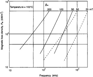
Figure 8.7 Magnetic loss (volume) density, PM, for two MnZn ferrites intended for power conversion applications. The solid curves are typical of power ferrites for switching frequencies in the range 50–500 kHz. The broken curves show the properties of lower permeability power ferrites designed for the frequency range 0.5–2 MHz. Courtesy of Drs. J. W. Waanders, Philips Components
For a conventional transformer core, the temperature rise normally limits the total core loss density to about 100–400 kW/m3, the larger figure relating to the smaller cores. The maximum allowable core loss density will set a limit on the flux density for a given frequency and this will enable the minimum number of turns required on a given core to be evaluated. The actual core loss is obtained by multiplying the total core loss density by the effective volume of the core as quoted in the data sheet for the core. In addition to providing loss data on their grades of power ferrite materials, some manufacturers quote the core loss in watts at given frequencies and flux densities for specific cores in their product range.
In the development of electronic power supplies, the priority is size reduction which leads to increasing throughput power densities. To accommodate this trend, switching frequencies are increased, the losses in the ferrites are reduced by material development and the power loss densities in the switching transformers are increased. To achieve higher loss densities in the transformers without exceeding a safe operating temperature, the trend is to use flat or planar geometries that can dissipate heat more easily. Such flat designs, which may be only a few millimetres high, are more compatible with pcb technology, can use windings based on printed circuit practice and can allow power loss densities as high as 700 kW/m3.
For the lower frequency power applications where the design is saturation rather than loss limited, it is important that the saturation flux density of the ferrite should be as high as possible at the operating temperature. This allows a high value of peak flux density to be used and minimises the required number of turns. Except in saturable reactor applications, a flux density excursion into the saturation region must usually be avoided, even under the worst overvoltage conditions, since it causes a steep rise in magnetising current that can damage the associated semiconductors.
8.4.1.2 Applications
Magnetically soft ferrites are used extensively as cores for inductors and transformers in industrial and consumer electronics. Referring to Table 8.2, the data in the first three classifications indicate typical properties of MnZn ferrites. The first is a low-loss ferrite intended for cores in high quality inductors used at frequencies up to about 300 kHz, such as inductors in filters for telecommunication applications. These cores are usually made in the form of cylindrical or square pot cores with an air gap to provide a specific effective permeability. There is usually provision for adjusting the inductance over a range of about ±10%. Such components combine potentially high Q-factors (300–1000) and good stability with temperature and time. The evolution from the early analogue to the present digital electronics has greatly reduced the proportion of ferrite cores required for such inductor applications.
The second column in Table 8.2 is representative of ferrite grades having high initial permeabilities and intended for cores used in low-power wide-band and pulse transformers. They are usually made in the form of rings and a wide range of E-core and pot-core shapes, some having low profiles compatible with pcb technology. The demand for wideband and pulse transformers increased dramatically with the introduction of digital networks such as Internet, and this in turn promoted the development of special high permeability ferrites having very low third harmonic distortion levels.
The third column refers to ferrites developed specifically for power applications. Initially the main application was the line scan (and high voltage) transformer in the domestic television receiver. The enormous growth in integrated circuit electronics led to a corresponding growth in the need for high frequency switched-mode power supplies This stimulated the development of ferrite materials and cores specifically for this purpose. Cores for use in power conversion are now second only in production volume to ferrite yokes used in cathode ray tube deflection systems. Originally switching frequencies were between 25 and 50 kHz, but the trend towards more compact power supplies and the attendant trend towards the use of resonant power conversion has progressively pushed these frequencies up towards 1 MHz and beyond. Figure 8.7 shows the magnetic loss data for two typical power ferrites, illustrating the development of improved performance at higher frequencies. When switching frequencies exceed about 3 MHz, even the best MnZn ferrites are unsuitable due to their increasing eddy current and ferrimagnetic resonance losses. NiZn ferrites, at the higher permeability end of their composition range, then offer superior performance.
Cores developed for power applications are generally variations of the E-core or U-core shape and many different designs are available. With the higher frequency applications, power loss densities become very high and this makes flat (low profile) geometries preferable, as described in Section 8.4.1.1.
The largest use of ferrites, by weight, is for yokes in cathode ray tube deflection systems. Most line deflection frequencies are relatively low so magnetic loss has not been a significant parameter in the design. However, in response to the need for better image definition, the line frequencies in domestic television receivers and, more particularly, in computer monitors are increasing; 100 kHz and even higher is quite common. Power losses are therefore becoming important in this application.
In addition to the uses outlined above, magnetically soft ferrites are employed in a variety of other applications, e.g. as rods for radio receiver antennas and tuning slugs in radio frequency coils. Ferrites with relatively square hysteresis loops are used for magnetic amplifiers in power control. With the increased use of electronic equipment and the stricter EMC regulations, electromagnetic interference (EMI) suppression has become an important application area for soft ferrites. Special ferrites have been developed to meet the requirements. In particular, ferrites in which the permeability and magnetic losses combine in such a way that the core presents an impedance that remains high over a broad frequency band. Above 1 GHz, ferrites having hexagonal crystal structures, such as those used for permanent magnets, are being introduced into the EMI suppression application. Traditionally, massive ferrite toroids have been and still are used as coupling cores in large particle accelerators. To conclude this very brief overview of the great range of ferrite applications, two very contrasting products can be included. High permeability ferrites, often in single-crystal form, are used in large quantities for magnetic recording heads in all types of analogue and digital recording equipment, and ferrites having the property of absorbing EM waves are produced as tiles, powders and granules for coating the surfaces of rooms and buildings to attenuate the reflection or transmission of EM energy at frequencies from hundreds of MHz to tens of GHz.
8.4.2 Microwave ferrites
Ferrites having special formulations are used in the non-reciprocal components (or gyrators) in microwave systems. This application of ferrites at microwave frequencies depends on the fact that the axis of the spinning electron (the magnetic element of the crystal lattice) will, if disturbed, precess with a rotational direction dependent only on the direction of the static magnetic field aligning the spins, and at a frequency that depends only on the static field strength. An electromagnetic wave, having positive circular polarisation relative to the static field direction and a frequency equal to the precession frequency, will couple to the spin precession to induce a resonance. There is no corresponding coupling or resonance for a negatively polarised wave. So a ferrite that is saturated by a static magnetic field and thus constitutes an array of aligned spins, will have properties that depend on the sense of the polarisation of an incident electromagnetic wave. Devices based on such material conditions will exhibit discrimination as to the directional properties of such a wave. This phenomenon gives rise to a family of waveguide and stripline devices used in microwave systems, such as unidirectional attenuators (isolators) and energy-routing components (e.g. circulators).
To meet the diversity of requirements found in microwave applications, many different magnetic oxides have been developed. Some are based on spinel (cubic) ferrites such as nickel ferrite, MnMg ferrite and NiCuCoMnAl ferrite. Magnetic oxides based on the garnet structure are extensively used in many applications, examples are yttrium iron garnet and gadolinium iron garnet each having a variety of substitutions to obtain the required properties.
8.5 Nickel–iron alloys
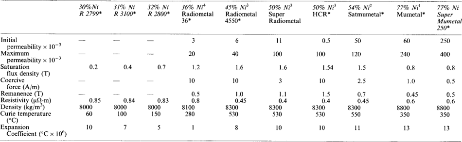
The nickel–iron alloys, ranging in composition from 30 to 80% nickel are the most versatile of soft magnetic materials. The design engineer can select from a wide range of available properties such as saturation flux density, permeability, coercive force and loss. The alloys can be subdivided into four main groups. Properties of a typical range of alloys are given in Table 8.3.
Table 8.3
*Carpenter Technology (UK) limited.
1,2,3,4BS 6064 Section 8.6, 1988. Classes E1, E2, E3, E4, respectively.
8.5.1 30% Nickel
The 30% nickel–iron alloy has a Curie temperature of the order of 60°C and exhibits a large linear change of permeability with temperature over the range −30°C to +40°C. This alloy property can be utilised in the form of a shunt to provide compensation for the change in the characteristics of a material, such as magnetic performance or conductivity, with temperature. Typical examples of such usage are watt-hour meters, speedometers and microwave circulators. The 31% and 32% nickel–iron alloys have Curie temperatures of 100°C and 150°C respectively and were developed for use in devices operating at higher temperatures.
8.5.2 36% Nickel
The alloy has a lower saturation flux density (1.2 T) and permeability than the 50% alloy but its lower cost and high resistivity make it an attractive alternative. The main applications are relays, high-frequency transformers and inductors. The alloy is also employed in devices, such as inductive displacement transducers, where its very low coefficient of expansion, 1 × 10⁻⁶/°C, is a great advantage.
8.5.3 50% Nickel
This alloy has the maximum saturation in the nickel–iron range (1.6T) and is used where a higher permeability and/or a better corrosion resistance than that of silicon—iron is required. Another advantage of the alloy is its high incremental permeability over a wide range of polarising d.c. fields. Applications include chokes, relays, small motors and synchros.
Special processing techniques enable a wide range of properties to be developed in this alloy. A cold reduction, in excess of 99%, produces a cube texture in the annealed strip and a square hysteresis loop. Applications utilising this property are magnetic amplifiers, inverters and pulse transformers. Annealing in a magnetic field, below the Curie temperature, can also alter the magnetic characteristics. If the field is applied in the conventional manner, both the initial and maximum permeabilities are substantially increased. When the field is applied in a transverse direction a very flat hysteresis loop with a low remanence is produced. These properties are ideal for thyristor firing circuits where a unipolar pulse is required and the transformer only operates between remanence and saturation.
8.5.4 80% Nickel
The high permeability and low coercivity of this group of alloys is due to the fact that both the magnetostriction and crystalline anisotropy are essentially simultaneously zero at this composition. Until the discovery of the cobalt-boron metal glasses and the nanocrystalline alloys with a similar combination of properties, the 80% nickel–iron alloys were unique for their ultra-high permeability performance.
The commercial alloys have additions of small percentages of molybdenum, copper or chromium to give improved magnetic performance over the binary alloy. Applications include sensitive relays, pulse and wide-band transformers, current transformers, current balance transformers for sensitive earth leakage circuit breakers and magnetic recording heads. Magnetic shielding is also a major area of application either in the form of fabricated cans or screens for transformers and cathode ray tubes. Annealed tape is also used in the manufacture of shielded cables.
8.6 Iron—cobalt alloys
The addition of cobalt to iron results in an increase in saturation, up to a maximum flux density of 2.45 T at 35% cobalt. The high cost of cobalt, relative to that of iron, restricts the widespread use of these alloys, although they are widely employed in the aircraft and associated industries. Their high Curie temperature and magnetostriction are also of special importance. Properties of a typical range of alloys are given in Table 8.4.
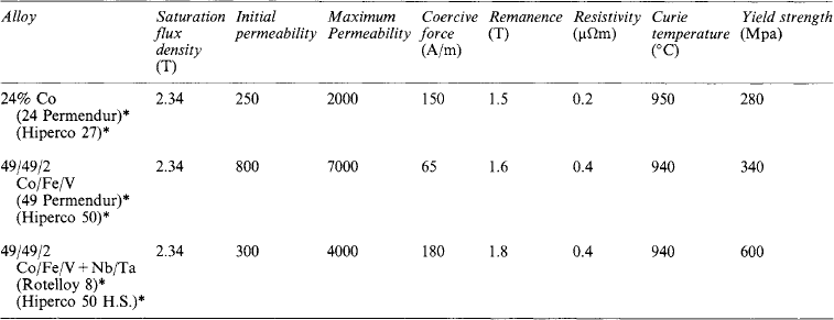
8.6.1 24/27% Cobalt iron
The ductility drops very considerably when the addition of cobalt exceeds 27% and compositions in this area are chosen for applications such as magnet pole tips where a combination of good ductility, ease of machining and high magnetic saturation flux density is required. The permeability, coercive force and loss characteristics are, however, inferior to the 50% cobalt alloy.
8.6.2 50% Cobalt iron
The optimum combination of magnetic properties is obtained in the 50/50 cobalt-iron composition. The ductility of the binary alloy is so low that it is not possible to fabricate the alloy to any extent. The addition of 2% vanadium greatly increases the ductility and fortunately, from the eddy current loss viewpoint, also substantially increases the resistivity. The 49/49/2 Fe/Co/V alloy has been extensively used for stators and rotors in lightweight electrical generators for many years. Other applications include lightweight/small-volume transformers, special relays, diaphragms, loudspeakers and magnet pole tips.
With Curie temperatures in excess of 900° C, this group of alloys is often the only choice for designers of equipment which incorporates soft magnetic materials that are required to operate at exceptionally high temperatures. A typical example of such an application is in the construction of the magnetic pumps used to pump liquid metal in the production of automobile engine castings.
The demand for increased electrical power in civil aircraft has forced designers to consider changing from the conventional constant frequency type of electrical generator to variable frequency or variable speed, constant frequency, machines. Higher centrifugal forces are exerted on the rotors of these machines, which operate at greatly increased speed. High strength cobalt-iron alloys have therefore been developed to meet these and other applications, such as magnetic bearings.
8.7 Permanent magnet materials
The properties of a permanent magnet material are given by the demagnetisation curve (Figure 8.8) the second quadrant of the B—H hysteresis loop. This extends from the remanence Br to the coercivity HcB. It can be shown that when a piece of permanent magnet material is put into a magnetic circuit, the magnetic field generated in a gap in the circuit is proportional to BHV, where B and H are the corresponding points at a point on the demagnetisation curve and V is the volume of permanent magnet material. This means that, to obtain a given field with the minimum volume of magnet material, we require the product BH to be a maximum. The magnet is then designed so that its BH value is as close as possible to the (BH)max value. It is also useful to use the (BH)max value, which represents the useful available energy, to compare the characteristics of materials. Generally, the material with the highest (BH)max will be chosen but this has to be weighed against such considerations as cost, shape, manufacturing problems and stability.
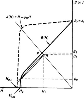
When the magnet is fully magnetised in a completed magnetic circuit with no gap, the working point is the remanence Br. When a gap is made in the circuit the magnet will be partly demagnetised and its working point will fall to, say the point P. If now a further demagnetising field is applied to the magnet corresponding to H1H2 the flux density will be reduced to B2. If this extra field H1H2 is removed the field will recoil along the narrow loop QR to the point R. The corresponding flux density is B3. This narrow loop is called the recoil loop and its slope is μ = μoμr where μr is the relative recoil permeability and μo is the magnetic constant (=4π × 10−7). This is an important consideration in dynamic applications such as motors, generators and lifting devices where the working point of the magnet changes as the magnetic circuit configuration changes. It is also important when considering premagnetising before assembly into a magnetic circuit. If μr is nearly equal to unity, as it is for ferrites and for rare earth alloys, then the magnets can be premagnetised before assembly into a magnetic circuit without much loss of available flux. However, if μr is considerably greater than unity, care must be taken to magnetise the magnet in the assembled magnetic circuit.
The dotted curve in Figure 8.8 is the J—H curve where B = μoH + J. For materials with Br much greater than μoHcB, e.g. Alnico, the two curves are almost identical, but for ferrites and rare-earth alloys where Br and μoHcB are close in numerical value the curves become quite different. The J—H curve has only a gentle slope from Br, this indicates that the magnetisation in the material is nearly uniform. A new parameter the intrinsic coercivity HcJ is introduced. This intrinsic coercivity HcJ is a measure of the difficulty or ease of demagnetisation. As the value of HcJ is increased the more will the material resist demagnetisation due to stray fields, etc. However, as a field of at least three times HcJ must be applied to the magnet for magnetisation, difficulties may be encountered in attaining the full magnetisation if HcJ is too high.
Magnets in the three main groups Alnico, ferrites and rare-earth alloys are generally made anisotropic with the properties in one direction considerably better than in the other directions. This best direction is called the preferred direction of magnetisation. The curves and parameters applied to such a material refer to the properties in this preferred direction. To choose between these three materials for a particular application, Alnico must be used where magnetic stability is a requirement and this will apply in any type of instrument application. Ferrite will be used where cost is the main consideration and rare-earth magnets will be used if the highest possible strength is required or if miniaturisation is needed
8.7.1 Alnico alloys
A wide range of alloys with magnetically useful properties is based on the Al—Ni—Co—Fe system. They are characterised by high remanence and available energy and moderately high coercivity. They are very stable against vibration and have the widest useful temperature range (up to over 500°C) of any permanent magnet material. They are however mechanically hard, impossible to forge and difficult to machine except by grinding and special methods such as spark erosion.
The commonest alloys contain 23–25% Co, 12–14% Ni, about 8% Al, a few per cent of Cu and sometimes small additions of Nb, Ti and Si, with the balance being iron. They are cooled at a controlled rate in a magnetic field applied in the direction in which the magnets are to be magnetised. The properties are much improved in this direction at the expense of those in the other directions. There is finally a fairly prolonged and sometimes rather complicated heat treatment at temperatures in the range 550–650°C. With the aid of the electron microscope it has been shown that after this treatment the magnets have a two-phase structure consisting of fine elongated magnetic particles separated by a non-magnetic phase, this structure being oriented by the magnetic field applied during cooling.
The field cooling is more effective in producing anisotropic properties if the magnets are cast with a columnar structure. Casting the alloy into a very hot mould placed on a cold steel plate produces this columnar structure. The moulds are usually made from exothermic material and the molten alloy is poured into this mould. This is a rather expensive process and there are limitations on the lengths and shapes of magnets that can be made into this columnar form.
The coercivity of Alnico can be improved by a factor of 2 to 3 by increasing the cobalt content to 30–40% and adding 5–8% Ti with possibly some Nb. For the best properties it is necessary to hold these alloys for several minutes in a magnetic field at a constant temperature, accurately controlled to ±10°C, instead of the usual field cooling process. This meticulous heat treatment as well as the high cobalt content makes these alloys expensive and they are only used where the higher coercivity is required. Columnar versions of these alloys can also be made but they are very brittle and are only used for very specialised applications.
The Alnico alloys can be produced as castings of up to 100 kg and down to a few grams in weight but it is found more economical to produce the smaller sizes of 50 g and less by the sintering process. It is always advisable to contact the manufacturers before any design is considered.
8.7.2 Ferrite
The permanent magnet ferrites (also called ceramics) are mixed oxides of iron (ferric) oxide with a divalent metal oxide usually either barium or strontium. These ferrites have a hexagonal crystal structure, the very high anisotropy of which gives rise to high values of coercivity, e.g. 150-300kA/m (compared with about 110 kA/m for the best Alnico alloys). The general formula is MO.5.9(Fe2O3) where M is either Ba or Sr. These ferrites are made by mixing together barium or strontium carbonate with iron oxide in the correct proportions. The mixture is fired in a mildly oxidising atmosphere and the resulting mixture is milled to a powder of particle size of about 1 μm. The powder is then pressed in a die to the required shape (with a shrinkage allowance), anisotropic magnets are produced by applying a magnetic field in the direction of pressing. After pressing the compact is fired. This compound is a ceramic and can only be cut using high speed slitting wheels. Ferrite magnets are produced in large quantities in a variety of sizes for different applications. Flat rings are made for loudspeakers ranging up to 300 mm in diameter with a thickness of up to 25 mm. Segments are made for motors with ruling diameters from 40 to 160 mm and rectangular blocks are made for separators with dimensions of up to 150 mm × 100 mm × 25 mm. These blocks can be built up into assemblies or cut down into smaller pieces for a variety of applications. In each of these cases the preferred direction of magnetisation is through the shortest dimension. Generally the magnetic length does not exceed 25 mm and if a longer length is required, this is built up with magnets in series.
The great success of permanent ferrites is due to the low price per unit of available energy, the high coercivity, the high resistivity and the low density. The isotropic grades are the least expensive to manufacture and may be magnetised into complex pole configurations; they are used for a wide range of relatively small sized applications. The largest application in terms of market volume is for magnets for motors which use high coercivity anisotropic ferrite in the form of an arc-shaped segment. These segments are magnetised radially and a pair of segments surround the armature and provide the stator field. The application for these d.c. motors is particularly in the automotive industry, e.g. for windscreen wipers, window movers, blowers etc. Another large volume application is for loudspeakers where the high remanence grades are used. Other applications of anisotropic hard ferrites include magnetic chucks, magnetic filters and separators.
8.7.3 Rare earth cobalt
The SmCo5 alloy was the first of the rare-earth permanent magnet alloys. The alloy powder is prepared by chemically reducing the rare earth oxide powder together with cobalt powder. The resulting powder is compacted and pressed almost invariably in a magnetic field to produce anisotropic magnets. The properties are due to a very strong magnetocrystalline anisotropy related to its hexagonal crystal structure. The range of sizes which can be produced is from about 1 mm cubes up to blocks of 50 mm × 50 mm × 25 mm, the short dimension being the preferred direction.
A more recent development is Sm2Co17 which is the generic title for a series of binary and multiphase alloys with a number of transition metals replacing some of the cobalt. These alloys have a number of advantages over SmCo5 alloys, they include a higher remanence Br and energy product (BH)max, greater temperature stability and lower material costs. This potential lower cost is however offset by the difficulties of production including a long heat treatment and inconsistency of properties. The good temperature stability, the best for the rare-earth alloys, makes it attractive for some applications.
8.7.4 Neodymium iron boron
The basic alloy is Nd15Fe77B8; it came out of efforts to produce high energy magnets which do not contain cobalt and from interest in amorphous alloys produced by very rapid cooling from the melt. When alloys of the appropriate NdFeB composition are recrystallised, a material with very good permanent magnet properties is obtained. The crystal structure of this alloy is tetragonal, the long axis being the preferred magnetic direction. The alloy powder can be produced by ball milling or by reduction of the neodymium oxide using calcium. However, a more popular development is to reduce the particle size of the alloy by contact with hydrogen. In this HD (hydrogen decrepitation) process, the hydrogen is absorbed with considerable expansion of the alloy causing it to break down into powder. The hydrogen is then pumped away. This is followed by jet milling to reduce the size of the powder to the optimum size. The resulting powder is then pressed in a magnetic field to produce an anisotropic compact and sintered. Throughout the processing the powder is kept either under a protective atmosphere or under vacuum to protect the neodymium from oxidation.
The advantages of magnets made from this alloy are that they have higher remanence Br and (BH)max than the SmCo alloys and they are also cheaper because Co and Sm have been replaced by Fe and Nd. The disadvantages are that they are subject to corrosion and to a rapid change of magnetic properties with temperature, particularly coercivity changes. Coating the magnets with polymer or metal films, depending on the application can prevent corrosion. The elevated temperature properties can be improved by additions of small amounts of dysprosium, gallium, niobium or vanadium. These last two elements may also give improved corrosion protection.
A further development of the HD process is the HDDR (hydrogen, disproportionation, desorption and recombination) process. This can produce very fine powder after a heat treatment under vacuum. This powder is suitable for the production of anisotropic magnets by pressure or for mixing with a polymer to produce bonded magnets.
8.7.5 Bonded materials
Each of the above materials can in the powdered form be mixed with a bond pressed to shape and cured either cold or in an oven. The bonds can be rubber, polymer or plastics and they may be flexible or rigid. The flexible rubber bonded ferrites have found wide application in holding and display devices and the best quality anisotropic material is used in small motors. Alnico and rare earth cobalt are also made in the bonded form, they have the advantage of a uniform level of properties and freedom from cracking. Bonded magnets are not so good as the cast or sintered materials, at best the (BH)max is about 50% of the solid forms.
For bonded NdFeB magnets the powder is very often made in the form of flake. Rapidly quenched melt spun ribbon is produced by ejecting molten NdFeB alloy through a fine orifice onto a rapidly rotating water cooled wheel. The ribbon is crushed into fine flake. The bonded magnets are produced by mixing the annealed flake with epoxy resin, pressing the mixture into the required shape and subsequently oven curing. The moulding procedure may be either injection moulding or compression moulding. Injection moulding is the best for bulk production but compression moulding provides better magnetic properties. This MQ1 flake material is isotropic and is used for a wide range of applications including hand held tools, holding devices and motors. Powder produced by the HDDR process mentioned above may be better for some applications as a higher (BH)max is possible than with the flake.
8.7.6 Other materials
There are a number of other permanent magnet materials with minority applications. This is often because they can be mechanically formed to shape, which is not possible for Alnico, ferrite or rare-earth alloys. It must be emphasised that these other materials are only available in a limited range of sizes and shapes.
Steels, which were the original permanent magnets, are now almost obsolete because their properties are inferior to those of the materials mentioned above. They do, however, find applications in hysteresis motors where lower coercivities are required.
CrFeCo is an alloy which can be rolled and drawn into wire, it has properties similar to those of Alnico. The alloy FeCoVCr can be drawn into wire, which produces the anisotropy. Platinum cobalt (PtCo) which has a very high coercivity was much used in the early days of space research. For most applications it has now been replaced by rare-earth alloys. However it is still used for medical and other applications where resistance to corrosion is required.
8.7.7 Properties, names and applications
The range of properties for each class of material is given in Table 8.5. These ranges include deliberate variations in properties obtained by small changes in composition and heat treatment.
Table 8.5
Characteristics of permanent magnet materials*
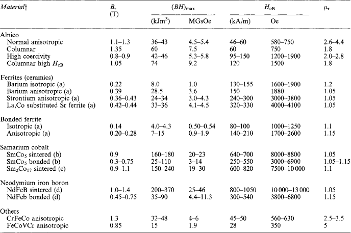
The Curie temperature of Alnico is 800–850°C, of ferrite 450°C, of SmCo over 700°C and NdFeB it is 310°C. The Alnicos have a resistivity of about 50 × 10−8 ω-m, for the ferrites it is about 104 ω-m and for the rare earths 90–140 × 10−8 ω-m.
*Br, remanence; (BH)max, energy product; HcB, coercivity; μr, relative recoil permeability.
†Intrinsic coercivity Hcj: (a) 160–400 kA/m, 2000–5000 Oe (b) 700–1300 kA/m, 8700–16200 Oe (c) 700–1650 kA/m, 8700–20600 Oe (d) 800–2500 kA/m, 10000–31200 Oe.
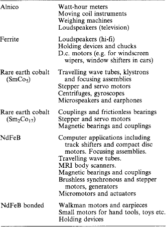
Permanent magnets have for many years been used for a wide range of applications. The ferrite (ceramic) magnets provide cheap magnets which are used for small motors and many other applications in the automobile industry. The ferrites are also used as ring magnets for radio and hi-fi loudspeakers and are prepared as blocks which can be cut up for a wide range of applications. The very great improvement in the available properties provided by the rare-earth magnets has focused interest on permanent magnet motors and the associated electronic equipment. In recent years there has been a movement from the SmCo alloys to NdFeB alloys but for some applications Sm2Co17 is preferred because of its better corrosion resistance and elevated temperature properties. Table 8.6 lists the important applications of the various permanent magnetic materials.
published by Beckley, P. Electrical Steels. New York: European Electrical Steels (now Cogent Power Ltd.); 2001.
, Soft Magnetic Materials. R. Boll. Newport, Gwent, UK: Vacuumschmelze Handbook, 1977.
Campbell, P., Permanent Magnet Materials and their Application, 1994.
, Rare-earth Iron Permanent Magnets. J.M.P. Coey, 1996.
Goldman, A. Modern Fernte Technology. Oxford: Van Nostrand Remgold; 1990.
Jiles, D. Introduction to Magnetism and Magnetic Materials, 2nd edition. New York: Chapman and Hall; 1998.
Lax, B., Button, K.J. Microwave ferntes and Fernmagnetics. London: McGraw-Hill Book Co.; 1962.
Gives a list of permanent magnet makers throughout the world McCaig, M., Clegg, A.G. Permanent Magnets in Theory and Practice, 2nd edition. New York: Pentech and Wiley; 1987.
Parker, R.J. Advances in Permanent Magnetism. New York: Wiley; 1990.
Gives a global list of soft fernte makers Snelling, E.C. Soft Ferntes Properties and Applications, 2nd edition. New York: Butterworths; 1988.
Wohlfarth E.P., ed. Ferromagnetic Materials. London: North Holland, 1980-1990. 6 vols continued with Buschow, K H to 10 vols (1998)
For more recent information it will be found useful to refer to:
IEEE Transactions on Magnetics which contains the proceedings of Intermag Conferences
Proceedings of International Workshops on Rare Earth Permanent Magnets from the University of Dayton Dayton OH, USA
MagNews published by the UK Magnetics Society, Berkshire Business Centre Wantage, Oxon OX12 8SH
15. IEC Standards on Magnetic Materials No 60404 parts 1 to 9 on the classification, methods of measurement and specification of magnetic materials, These standar