
Hazardous Area Technology
25.1 A brief UK history
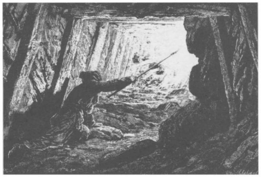
In the early days of coal mining (with candles or oil lamps as the only form of lighting) it was soon learnt that explosions could be caused if an accumulation of gas occurred when working a coal seam. It was also soon realised that the gas tended to collect along the top of the tunnels, so someone (the original fireman!) had the unenviable job of crawling along the tunnels in advance of the miners, carrying a candle on the end of a pole (Figure 25.1). They could reach to the roof and if gas was present at that level, it would hopefully be ignited and burnt off without major problem, thus rendering the area safe to work in. This system was by no means foolproof, and on occasions when a large concentration of gas was encountered there could still be a major fire or explosion. The Davey lamp was the first major step forward in this situation. Its design was such that the flame within the lamp would not propagate through the metal gauze surrounding it so it would not ignite the surrounding atmosphere. At the same time, the colour of the flame showed when the explosive gas was present, so giving a good warning to take extra precautions.
With the advent of electricity and resultant mechanisation, more thought was needed in guarding against the ignition risks from electrical or frictional sparks or hot surfaces, and a major mining disaster around 1913 served to focus attention even more on the risks. Around this time the safety in mines research establishment (SMRE) was formed, and located near the small village of Eskmeals on the Cumbrian coast, but hopefully far enough away so as not to disturb people with any test explosions which occurred.
In the mid 1920s SMRE moved its testing facilities to Buxton in Derbyshire, again placed on a hill out of town so that any explosions would not worry the neighbours. In mining, both flameproofing and intrinsic safety gained ground as accepted protection techniques, in combination with forced ventilation to keep the gas concentration below explosive levels whenever possible. At the same time as SMRE assisted with the safety of equipment in the mines, the board of trade (BoT) looked after the safety of surface industries such as chemical works and oil refineries. As electrical installations became more complex, a system of issuing certificates for both apparatus and intrinsically safe systems was developed, to ease the job of inspectors checking an installation. The first standards used were some early British Standards such as BS229 and BS 1259, which were very brief and general in their wording, so that they almost let the certifying officer make up his own rules for certification. At this time (the 50s and 60s) the certification was still carried out by the factory inspectorate, and gradually the proliferation of electrical installations led to increasing delays in inspecting sites. In 1967 the British Approvals Service for Electrical Equipment in Flammable Atmospheres (BASEEFA) was formed to take over the basic certification of apparatus from the factory inspectorate and so ease their load.
In the early 70s BASEEFA produced its own more detailed standards, in particular for intrinsic safety, special protection, and gas detectors using pellistors (both for explosion protection and for performance). Then in the mid 70s, the major explosion and fire at Flixborough focused attention even more on the need for safety in electrical equipment, the influence of the European Union was gaining ground, and a series of harmonised standards (the EN 50014 to EN 50020 series plus one or two others) was evolved for use by all the member states. These standards were published in 1977 in the UK by BSI, as BS 5501 Parts 1 to 7 and others.
When BASEEFA was first set up the certification went hand in hand with a licence to reproduce the BASEEFA mark, which in turn was conditional on the manufacturer having an acceptable quality control system in place to ensure the certified equipment was made correctly. Also with the advent of the EN 50014 series of standards, there was a general comment in them which placed a responsibility on manufacturers (and arguably on certification bodies too) to ensure product was made correctly. The BASEEFA licence was issued in conjunction with a surveillance visit (or audit) as a third party check on production quality. Whilst such audits were common with regard to American organisations such as Factory Mutual (FMRC) or Underwriters Laboratories (UL), they tended to be the exception in Europe, with BASEEFA being possibly the only certification body carrying out such visits, and pressure mounted from some quarters for these audits to be drastically reduced if not phased out completely. However, at least one of the large user companies became very dissatisfied with the acceptability of goods it was receiving from various companies both in the UK and the rest of Europe, and so led a push to reinstate and reinforce the quality audit situation. The problem was not poor quality of equipment, but that well intentioned changes to the design to improve functionality or ease manufacture sometimes resulted in non-compliance with the strict interpretation of the standards and hence invalidation of the certificate. The worry was that sooner or later such a problem might go beyond a technical non-compliance and actually result in an unsafe piece of equipment being installed somewhere. This resulted in BASEEFA launching its conformity assurance programme for quality auditing. Now as we enter the 21st century quality control in general has achieved prominence, and the new ATEX directive legislation has introduced a clear quality module into the certification process, so that quality requirements will be recognised and enforced throughout Europe. This is mentioned again later on.
For many years various testing and certification bodies throughout the world have met at regular intervals to exchange knowledge and experiences, and this has led to a gradual convergence of the various explosion protection standards. The latest editions of the EN 50014 series of standards (now numbered by the British Standards Institution as BSEN 50014, etc.) are the basis for ATEX directive certification, and greater alignment is also being achieved with the IEC 60079 series of standards which will eventually open the way for global certification with the IECEx scheme. One immediate advantage to users of certified equipment is that the marking of apparatus will become very nearly the same anywhere in the world. These will be mentioned in more detail later in this chapter.
25.2 General certification requirements
Most countries in the world have government regulations, or general requirements laid down by insurance companies, or both, requiring workplace managers or owners to take reasonable precautions to ensure the safety of their employees and the general public. For example in UK there is the health and safety at work act 1974 plus the working regulations 1996 act, or in the USA, OSHA (the Occupational Safety and Health Administration) which is one of the US Government Agencies.
The need for using certified apparatus in a particular situation depends on several factors, such as the quantity of flammable material present, how the material is handled and contained, what ventilation exists, and how large the work area is in comparison to the quantity of flammable material.
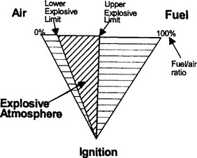
The explosion triangle shows the elements needed to create an explosion (Figure 25.2). The first obvious means of explosion protection is to keep ignition sources away from the flammable material. The next can be to ensure that there is plenty of ventilation, so as to keep the air fuel mixture below the lower explosive limit. Some people would suggest that ensuring air is totally excluded so that there is always 100% fuel is also a ‘safe’ situation to aim for, which in turn would allow invasive probes to be included directly into the process system without any need to use certified types. This is debatable; as although some countries’ test authorities will accept it as a safe situation, others would argue that you could well at some time run into a potentially explosive situation if there was a problem with the process and air entered during the repair period. Then great care would be needed when refilling the system to ensure all air was flushed out before re-energising any non-certified invasive probes.
As mentioned earlier, in mining, forced ventilation is used to dilute any gas and keep the mixture well below the explosive limit. In surface industries, natural ventilation may be sufficient much of the time, especially if the work area is large compared to the amount of flammable material being handled. Another factor in siting equipment can be the density of the flammable mixture, which would determine where the mixture might concentrate most (floor or ceiling). For further guidance on assessing the disposition of hazardous areas, see BSEN 60079-10.
The probability of an explosive atmosphere being present is based on a system of zoning.
Zone 0 is where a hazardous (or explosive) atmosphere may be present continuously or for long periods, for example within or immediately around a vessel containing a flammable liquid, or within the pipework of some process.
Zone 1 is where the explosive atmosphere can be present in normal operation, but for a more limited period of time. This could be where (normally sealed) containers of flammable liquid are kept and at regular intervals the liquid has to be poured, thus releasing vapour into the surrounding atmosphere. A common rule of thumb is to say if the vapour is likely to be present for less than around 100 to 1000 hours per year then this constitutes a zone 1 area as opposed to zone 0.
Zone 2 is where an explosive atmosphere is not normally present but could occur under fault conditions. This could be a storage area where the flammable material is kept in sealed containers, but spillage could occur if a container was accidentally dropped and ruptured.
In America and Canada, the area classification up to now has been by division. In this system division 2 is very similar to zone 2, but division 1 encompasses both zone 0 and zone 1.
The zoning system is beginning to be used with the advent of the latest standards discussed later, but it remains to be seen how long it takes to gain general acceptance in those countries.
25.3 Gas group and temperature class
The next factor which comes into play is the sensitivity of the explosive atmosphere to possible ignition sources. Materials are classified by minimum ignition energy (m.i.e.) based on how easily they will ignite due to a spark, maximum experimental safe gap (m.e.s.g.) based on how easily they will transmit a flame through a small gap, and auto ignition temperature based on how easily a hot surface can ignite them. The m.i.e. and m.e.s.g. tend to go fairly closely together. For example hydrogen is the most onerous gas in this respect, and both the permitted energy in intrinsically safe equipment and the permitted gaps in flameproof equipment are the smallest. The auto ignition temperature, however, tends to work independently. Using the hydrogen example, its ignition temperature is around 560°C, so hot surfaces are not a particular problem, whereas many other explosive mixtures could be ignited by temperatures around say 250°C or 300°C.
The gases, based on m.i.e. and m.e.s.g. are classified into subdivisions which align with the apparatus groups shown in Table 25.1. BSEN 50014 and BSEN 60079-0 both contain information on the subdivisions of many compounds, and includes IEC/TR3 60079-20 also include auto ignition temperature information for a large range of compounds. The auto ignition temperature is used to determine the suitability of apparatus for use with a particular gas, by reference to the apparatus temperature class. For compounds not listed, the health and safety laboratory or other specialist laboratories may be able to provide advice or testing to allocate the material to the appropriate group or temperature class.
Table 25.1
| Representative gas | Group (European or IEC) | Group (USA and Canada) |
| Acetylene | IIC | A |
| Hydrogen | IIC or IIB + H2 | B |
| Ethylene | IIB | C |
| Propane | IIA | D |
| Methane | I |
In the USA and Canada the group marking usually lists all the group letters applicable, such as ‘for group D’ or ‘for groups A, B, C and D’, whereas in the group marking for european or IEC, a mark of IIC automatically implies that the apparatus is also suitable for IIB and IIA, and IIB implies suitable for IIB and IIA.
Note that acetylene is listed separately in the Table 25.1 the reason for this will be explained when discussing flameproof equipment later in this chapter.
Temperature class sometimes causes confusion, so hopefully this explanation will help to clarify things. The temperature class marked on a piece of apparatus gives indication of the likely maximum temperature which will be reached in service (either in normal operation or under certain fault conditions). In the absence of anything more than the temperature class, the implication is that this will be the maximum temperature of the apparatus when located in a surrounding ambient not exceeding 40 °C. For other ambient temperature ranges and extra marking such as (-20°C < Ta < + 60°C) will be included. Now the gas mixture of concern will have either a suitable temperature class or an auto ignition temperature (or both) shown, and provided the temperature class of the apparatus is equal to or ‘better than’ that for the gas mixture, then the apparatus is suitable. For example, if a gas mixture was shown as requiring T2, then apparatus of T2 up to T6 would be suitable, but not T1, or if the mixture was quoted as having an auto ignition temperature of 180°C then apparatus of T4, T5 or T6 would be suitable, but not T1 to T3.
Table 25.2
| Temperature class | Temperature of apparatus (°C) |
| T1 | 450 |
| T2 | 300 |
| T3 | 200 |
| T4 | 135 |
| T5 | 100 |
| T6 | 85 |
In America and Canada, when working to their earlier standards, some temperature classes may be further subdivided with a suffix, such as T2A to T2D which refer to intermediate temperature steps. They are omitted from this description for simplicity, but full details can be found if required on the appropriate websites.
25.4 Explosion protection concepts
Table 25.3 repeats the zoning mentioned earlier and shows the types protection permitted in each zone.
Table 25.3

25.4.1 Intrinsic safety ‘i’ (which may be subdivided into ‘ia’ or ‘ib’)
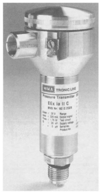
This technique is used mainly for electronic equipment such as level, density or temperature transmitters, toxic or combustible gas detectors, or proximity detectors, or portable radio transceivers. The power levels involved are relatively small, usually less than 1.3 W, but in some cases up to around 5 or 6W. For fixed apparatus fed from a separate power source, both the hazardous area apparatus and the power source itself are designed so as to ensure that under fault conditions, any spark energy or surface temperature is insufficient to cause an ignition of a surrounding explosive atmosphere. The spark energy has an extra safety factor applied to it, and the temperature is assessed under worst case fault conditions to provide a safety factor there also. The power source may be a custom designed power supply or control unit, or a general purpose zener barrier or repeater power supply. ‘ia’ relies on a two fault analysis and is suitable for use in zone 0, and ‘ib’ relies on a one fault analysis and is suitable for zone 1. This type of equipment may also be self contained battery powered (Figure 25.3).

Figure 25.3 An example of a battery powered hand held intrinsically safe instrument. Photograph courtesy of Ion Science Ltd
For the fixed installation with separate power supply, the cabling linking the two is specified in terms of capacitance, inductance and inductance to resistance ratio, but otherwise can be almost any lightweight cable, which can save on installation costs. Also the equipment tends to be very light and manageable in comparison with other protection concepts, because the enclosure is basically only required to keep the circuitry clean rather than being a vital part of the protection concept. Another advantage is that ‘live maintenance’ is possible, whereas with other protection concepts the equipment usually must be de-energised before any work is carried out. The consideration to be offset against this is that both the power source and the hazardous area equipment must be certified, and in general only equipment operating at 30 V or lower and 5 W or lower is available.
This equipment is sensitive to gas group, and may be certified for IIC, IIB, IIA or I. As hot surfaces may be present, the temperature class also needs checking against the gases present where it is used (Figure 25.4).
25.4.2 Flameproof enclosure ‘d’
This technique is often used for such things as luminaires, valve actuators, high powered control units and heavy duty motors and pumps. It is also used for level, density or temperature transmitters of similar size to those certified ‘i’, but in situations where for various reasons the user happens to prefer the ‘d’ concept. In this technique the enclosure is designed to be strong enough to contain an internal explosion, and with covers, cable glands, etc. arranged such that any gaps (or flamepaths) to the outside world are small enough to ensure that the internal explosion will not be transmitted to the surrounding atmosphere. Testing for non-transmission and the pressure test both have an extra safety factor applied compared to normal operation, to give the required integrity. The obvious advantage compared to ‘i’ is that high powered equipment operating up to several hundred volts can be protected ‘d’. To be offset against this is that even small equipment can be relatively bulky and heavy, and the cabling always needs to be well protected, either by use of armoured cable or by use of conduit or other mechanical protection (Figure 25.5).
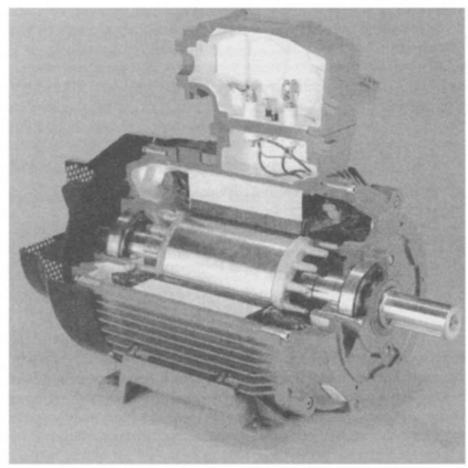
Figure 25.5 Sectional illustration of an EEx ‘d’ induction motor (courtesy of Invensys Brook Crompton)
Acetylene is dealt with as a separate item in the flameproof standards because it has a unique characteristic compared with other flammable or explosive mixtures which causes problems with this equipment. If the acetylene mix is very rich, it produces carbon particles, and whilst a properly dimensioned plain flange will stop normal flame propagation, it does not prevent incandescent particles being ejected. Thus acetylene requires the use of such things as spigot joints or threads to provide added integrity.
This equipment is also sensitive to gas group, and may be certified for IIC, IIB, IIA or I, and again the temperature class needs checking for suitability. With this type of equipment, the temperature of internal components may be much higher than the external surface of the enclosure, which is permissible in normal use, but can result in extra conditions being imposed when it is necessary to open the equipment, such as de-energising and waiting a specified minimum time before opening.
25.4.3 Increased safety ‘e’
Typical equipment here includes luminaires, induction motors, pumps, etc. This technique relies on ensuring that all components are run well within their capabilities so as to avoid hot surfaces, and connections are arranged to be of high reliability so that they will not produce sparks. Again the advantage here is that high powered equipment can be protected this way, the weight and bulk tends to be somewhat less than ‘d’ equipment, but still the cabling needs to be well protected.
This equipment is not sensitive to gas group as it is essentially non-sparking, so the group marking is likely to be just II implying any gas group, however the temperature class may still vary and so need checking against the gases present in the location where it is used (Figure 25.6).

25.4.4 Purged and pressurised ‘p’
This technique relies on keeping the explosive atmosphere away from the live electrical circuits, by dilution with air or inert gas. Depending on the nature of the equipment being protected, either the unit may be a sealed enclosure (with probably an air or inert gas bottle attached) with a very low leakage rate, or it may be deliberately ventilated by means of a fan bringing in air from a ‘clean’ location. In each case the technique relies on monitoring the internal pressure of the unit, or the flow rate, or both, and cutting off the electrical supply to the unit if the pressurisation fails. When starting up the system it is necessary to monitor the pressure and/or flow and ensure the enclosure is up to pressure and has been flushed ‘clean’ (or purged) before re-energising the electrical circuits. The control equipment is often used in conjunction with some ‘i’ or maybe ‘d’ circuits, to enable fully automatic start-up.
Basically while the pressurisation system is operating, neither the gas group nor the temperature class are of any consequence in respect of the items within the enclosure, but clearly any residual high temperatures will be of concern if the system fails, and any associated ‘i’ or ‘d’ equipment will need to be chosen to suit the gasses involved (Figure 25.7).

25.4.5 Quartz filled ‘q’
This technique uses quartz filling around the hot or sparking components to prevent spark emerging into the surrounding atmosphere and to keep external temperatures to a suitable level. This seems to have found some favour in Germany, but has not particularly been used in the UK so far.
Again this technique is not gas group sensitive, but the temperature class needs consideration.
25.4.6 Oil immersion ‘o’
With oil immersion, the sparking or hot parts are totally covered in an oil bath. Again this technique is not as popular as other methods of explosion protection, although there are some situations where it is the only practical alternative.
Again this technique is not gas group sensitive, but the temperature class might need consideration. One possible disadvantage is that the oil itself is flammable, and there have been incidents where the oil has ignited under severe fault conditions.
25.4.7 Encapsulation ‘m’
This relies on the circuits being covered with a certain depth of encapsulating material. For this technique the encapsulant has to survive various tests to prove its durability, and ability to survive the possible temperatures in the encapsulated circuit.
This technique is not sensitive to gas group but always carries a temperature class.
25.4.8 Non sparking ‘n’
This technique is suitable for zone 2 only and uses a combination of suitable enclosure, adequate rating of components, temperature limitation, and non-sparking circuits (such as sealed relays) and if necessary energy limited circuits where any spark is non-incendive, or enclosed break components (which are similar to flameproof, but accepted on the basis of passing a test for non-transmission of an ignition, but without any specific minimum mechanical requirements). The philosophy is that once the requirements of the standard are complied with, then the chances of a fault occurring in the apparatus at the same time as the explosive atmosphere is present are so small as to be ignored.
The gas group marking may be II or IIA, IIB or IIC depending on whether or not the equipment incorporates energy limited circuits or enclosed break components, and there will also be a temperature class.
25.4.9 Special protection ‘s’
This standard is unlikely to be used in future. The UK version was a BASEEFA standard which contained various extra tests and guidance to enable certification of apparatus which did not exactly fit the other standards in existence at the time, but could be shown to be of ‘equivalent’ safety. It was a national standard, with each European test house having its own similar version, but entailed re-certification in each country where the apparatus was used. It was introduced in 1972 in the UK and updated in 1985, but since then some of the principles in it have been incorporated into later versions of the flameproof Standard BSEN 50018, and into EN 50028 for encapsulation ‘m’. Also the introduction of BSEN 50284 along with ATEX has come along, so that the standard is now very close to becoming redundant, as most if not all equipment may now be covered for use throughout Europe by means of the newer harmonised standards, or directly against the EHSRs of the ATEX directive.
25.4.10 Mixed concepts
The are some situations where, for various reasons, a piece of equipment is protected by more than one technique. The most likely combinations which will be seen in practice are ‘di’ or ‘id’, ‘d[i]’, ‘emi’, ‘de’ and ‘n[i]’.
The [i] combinations are often used to enable intrinsically safe barriers or repeaters to be mounted in a ‘d’ or ‘n’ enclosure. The interior of that enclosure then counts as a safe area for the barriers and the enclosure can then be located nearer to the instrumentation which the barriers feed than might be possible by relying purely on mounting them in the main safe area.
A common practice is to fit a ‘d’ motor with an ‘e’ terminal chamber, to save a little weight. In this situation, the motor and terminal chamber might each carry their own certification, or there might be just one certificate for both, coded ‘de’.
The other combinations involving ‘i’ may occur for a variety of reasons. One example is a gas detector using a pellistor element. The pellistor element uses a catalytic effect to ‘burn’ the surrounding gas and usually needs to be contained in a ‘d’ enclosure in order to prevent the flame propagating to the surrounding atmosphere. At the same time the remainder of the circuit often can be certified ‘i’, so that the equipment is coded ‘di’ or ‘id’. Other examples could be various forms of gas analysers or detectors, or maybe smoke or vapour cloud detectors, where for technical reasons sufficient power is required in the main circuits that they need to be ‘d’ or ‘em’, but for ease of maintenance the sensors themselves and maybe their calibration adjustments are ‘i’ so that they can be exchanged or adjusted at any time without having to de-energise the equipment. It is worth noting here that is possible for equipment to be coded ‘dia’ for example, and there can be a slight conflict of understanding here as ‘d’ is a zone 1 concept, whilst ‘ia’ can be zone 0. The general rule to apply here is that in the absence of other information, the lower zone takes preference, and the overall equipment is only suitable for zone 1. There are situations where the ‘ia’ part may be placed in a zone 0, or be attached to pipework containing a zone 0 sample, and this will be explained fully in the certification and/or the manufacturer’s instructions for the particular equipment. (Figure 25.8)
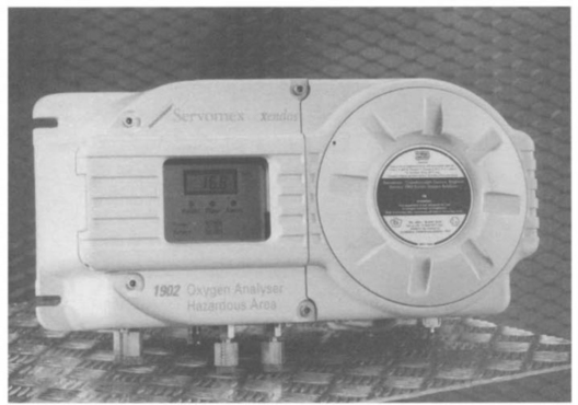
Figure 25.8 Example of a mixed concept apparatus which aids routine maintenance and adjustment. The circular threaded cover allows entry to a flameproof chamber and so must only be opened when de-energised, and under any other specific conditions which might be stated on the unit or in the associated documentation. The chamber behind the display contains only intrinsically safe circuits, thus permitting it to be opened at any time to allow access to, and live adjustment of, calibration or alarm setting controls, but subject of course to any extra operational conditions laid down by the manufacturer. Photograph courtesy of Servomex Group Ltd
Other combinations of codes are not precluded, but the author has not necessarily seen them in practice.
25.4.11 Dust protection
Historically some extra requirements for coal dust protection have been included in the standards mentioned above, to take account of mining situations. This meant that there was a fixed maximum permitted surface temperature of 150°C for any surface or component where coal dust could form a layer, or 450°C on any part where coal dust did not have access. Note that the temperatures shown here are for the very specific case of coal mining where coal dust and methane or firedamp are present. The prevention of access by coal dust was achieved by having an enclosure sealed to at least IP54.
For some time in North America, dust protection requirements have been included in the explosion protection standards for their class II and III, groups E, F and G, but with different (lower) temperatures and different enclosure sealing requirements, depending on the particular dust or fibre concerned.
In Europe, generalised dust protection was covered in various standards, but not specifically included in the explosion protection requirements until the advent of ATEX (see below). Now EN 50281-1-1, EN 50281-1-2, EN 50281-2-1 and others are being used to bring in dust protection here too. Equipment can be certified for use in dust areas only, or with dust and gas. Depending on the severity of conditions anticipated in service, enclosures may be IP5X (dust protected) or IP6X (dust sealed), and the temperature of the apparatus may be based on just a thin coating of dust, or on the possible increased temperature when covered with a thick blanket of dust. The marking used on the apparatus is dealt with under the ATEX heading.
25.5 ATEX certification
The European harmonised certification which came into operation during the 1980s had problems with respect to the introduction of amendments to—or new editions of—the relevant harmonised standards. The original EC directive was precise in specifying the exact issue level of each standard, so that each time a standard was changed, another modifying directive had to be issued to incorporate the new amendment level of the standard. Each country would put the standards or amendments in place ready for use, but they could not be used in the actual certificates until that modifying directive was issued. This caused confusion at times for all concerned, as manufacturers or users would obtain copies of the new standards and expect certificates to incorporate them immediately, whilst the certification bodies would have to refuse to include them until the appropriate EC directive appeared.
One of the main themes behind the ATEX directive is intended to overcome this problem. There is a phrase in the directive along the lines of ‘taking account of technological advances’, which means that certification bodies will use the latest published version of a standard at the time of the certification.
The ATEX directive uses a set of essential health and safety requirements, referred to at various times in other articles as ESRs or EHSRs. These are couched in general terms and cover many, if not all, aspects of hazard to persons, for example integrity of pressure systems and radiation of various types, instead of just possible ignition of explosive atmospheres. The EHSRs also effectively include mechanical as well as electrical sources of ignition, and cover protection against flammable gases or dusts.
At the present time ATEX certification can be used voluntarily as an alternative to the previous certificates of conformity, but from July 2003 any new installation will have to be in compliance with ATEX. Two situations are clear cut at that time: first, any brand new installation will have to meet ATEX; second, existing installations will be able to remain in service for the remainder of their useful lives. The area which is slightly unclear at present is that of repairs and maintenance on those installations. There is bound to be debate in some situations as to how much can be done in the name of a repair and where it becomes new equipment. Also the ATEX directive talks in terms of ‘equipment placed on the market’ after July 2003. At present there is a feeling that manufacturers or users could maybe ‘stockpile’ a reasonable number of units for repair purposes, but what is a reasonable number, and would the manufacturer be permitted to hold that stock, or would they have to be sold to the user before the due date and held by him? This is something to which there is no clear answer right now, and it remains to be seen how things develop once ATEX is fully in force.
25.5.1 Example of an ATEX label
AAAA is up to 4 letters identifying the notified body which issued the type examination certificate.
00 is the year of the certificate
ATEX shows it is an ATEX certificate
nnnn is the serial number of the certificate

xxxx is the number of the notified body carrying out the quality module of the ATEX requirements. This Cε mark together with the four digit number may appear in addition to any other Cε mark which the manufacturer may need to apply for other purposes.
The G in the II 1 G signifies protection for gas, and could be replaced by D for dust, or G D for both gas and dust. If the apparatus is protected for dust, there will be two further items on the label: the enclosure degree of protection, which must be at least IP54 for category 3 and IP65 for category 1 or 2, and the maximum surface temperature of the enclosure (shown as Txxx°C).
25.6 Global view
Both the earlier harmonised standards and ATEX arrangements were intended to ensure acceptability of certified apparatus in any European member state without repeating the certification every time.
From the certification body and manufacturer aspect, a strong trend has already developed towards one-stop assessment and testing for several other countries. Various agreements are in place between many organisations in Europe, Canada, America, Australia and Japan among others, whereby one certification body can provide assessment and testing of the design to several standards at the same time and issue a report to the other co-operating body. The equipment still has to be finally certified or approved by the appropriate organisation in the country where it is to be used, but the initial ‘combined’ assessment can help in achieving a ‘universal’ design first time and avoid having to keep redesigning the equipment for each authority in turn, with the resultant delays and inconvenience this was likely to cause.
Historically the various standards relating to intrinsic safety all used basically the same set of ignition curves originated by SMRE in the early 70s and supplemented by more research work by PTB in Germany in the 90s. Similarly, the test gas mixtures used in both intrinsic safety and flameproof testing tend to be the same throughout all the standards. However the exact application of factors of safety applied in testing or interpretation of the curves varies from standard to standard, which is one reason why it has been necessary to have equipment certified separately in every country where it is used.
Even when the equipment itself is certified to the harmonised standards within Europe, each member state tends to have its own installation requirements which need to be taken into account. The advent of EN 60079-14 (Code of practice for installation) lays the foundation for hopefully a more universal set of installation practices.
In the long term the IECEx scheme of certification (based on the IEC 60079 series of standards) is heading in the direction of providing certificates which would be acceptable in any participating country, so eventually full global certification is a possibility. At present the scheme is still only being used on the basis of an assessment and test report (ATR) produced in one country being accepted as the basis for certification in another country. At this time there are still too many national differences compared to the IEC Standards to enable direct acceptability of any country’s certificate in any other country, but the long term aim is to reach that situation, around 20 countries have so far signed up to the IECEx scheme with around a further 5 showing interest.
It is also worth mentioning again here that the style of coding similar to EEx ia IIC T4 is becoming more and more the usual arrangement to look for, which should avoid the confusions which tended to occur in the past. The variations in this coding are likely to be only such things as the EEx changing to Ex for the IECEx scheme, or AEx for American approval, but the protection concept, gas group and temperature class will be recognisable throughout.
25.7 Useful websites
In this technological age, there is a plethora of information available on the internet. The following is a list of useful websites found by the author, with apologies to those not included.