
Aircraft
47.1 Introduction
Modern aircraft have come a long way since the Wright brothers built their first aircraft in their bicycle shop in Dayton, Ohio, and made the first powered flight of an airplane in 1903, at Kitty Hawk, North Carolina. This first crude biplane, however, embodied the two basic elements of all modern airplanes; namely a propulsion system and lifting devices (wings). Since that time, the technologies of propulsion and wings have made significant strides in the science of aviation.
Progress in technology, as in medicine, is stimulated significantly during wartime and World Wars I and II played a major role in advancing the basic design concepts of the modern (military and civil) airplane, as well as bringing about major improvements in the power plants. Prior to World War II, aircraft were powered initially by internal combustion engines in the 1600–2800 hp range, but during that war the first jet-powered aircraft emerged.
47.2 Engine technology
From the simple rudimentary two-stroke gasoline piston engines developing a mere 60 hp, engines moved from the small 150 hp piston engines that powered the World War I biplanes (such as the Bristol Bulldog, Sopwith Pup, Avro 504, the French SPAD and the German Fokker aircraft) to the 1600 hp/1800 hp ‘radial’ and ‘in line’ piston engines that were used in the four-engined bombers in World War II. The radial engines were designed for propeller/ram-air cooling: the air stream from the former being used to provide blast-air cooling of the ‘finned’ piston housings (during static conditions on the ground) and ram-air cooling, during taxi and flight conditions. The ‘in-line’ engines, in contrast, were liquid cooled, as exemplified by the Rolls-Royce Merlin engine that powered the early Spitfire at some 340 mile/h in its record-breaking test run at a Schneider Cup Race in 1927. The advantages of the ‘in-line’ engine in this case were its low frontal area, which permitted power-plant streamlining and, therefore, reduced power-plant drag.
From these early World War II engines, the designers explored other piston-engine technology such as Bristol’s ‘sleeve-valve’ engine, named the Centaurus, that had a take-off power rating of approximately 2800 hp. This engine was unique in that it eliminated the complex ‘poppet-valves’, with their push rods, cams, etc. In the Centaurus engine, the equivalent of the conventional inlet/exhaust valves was provided by an inner ‘sleeve’ cyclinder, within the piston housing, that had machined ports (openings) that successively exposed the inlet and exhaust manifolds to the combustion chambers; as the sleeve moved up and down with an oscillatory motion. Napier also developed a double ‘12-pot’ engine arranged with the rear 12-pot engine ‘staggered’ (for cooling purposes) behind the first: this 24-cylinder engine was rated at 2850 hp. Another novel engine development by Napier was the Nomad engine which uniquely combined a turbine engine with a diesel engine, to yield attractive fuel and weight savings. The following is Napier’s weight estimate of typical four-engined aircraft, carrying the same payload over a range of 2860 miles.
(where lbf is pounds-force and shp is shaft horsepower).
Higher horsepower engines were developed in the 1940s and were used during World War II. The most notable US fighter at that time was the Curtiss 1-40 Warhawk which used an Allison 12-cylinder liquid-cooled in-line engine that developed 1200 hp. This period was also of note in that engine (propulsor) technology moved on from the internal-combustion-engine design to the turbojet and turboprop designs. Frank Whittle’s gas turbine engine, built and tested in 1930, was the precursor of these jet engines which were to set the trend for these advanced propulsors in the military and commercial aircraft. The first early military aircraft application of the jet engine in World War II was in Germany’s Messerschmitt Me262A which had a maximum speed of 540 mile/h. This jet-engine-powered aircraft was followed by the UK’s Gloster-Meteor aeroplane with two Rolls-Royce Derwent engines, developing 2000 lbf each: these two engines provided the Meteor with a top speed of 520 mile/h.
Early turbine engines were rated in the 2000-5000 lbf range, but this was soon to increase to 10000 and 20000 lbf. The Pratt & Whitney PW7000 is an example of a modern 20 000 lbf engine.
During the 1950s, engine thrusts increased to 48 000 lbf as in the case of the Rolls-Royce RB.211, the GE-CF6 and United Technologies P&W JT-9D engines. These engines powered the Lockheed L-1011, Douglas DC-10, Boeing B-747 and many other aircraft. These engines foreshadowed the emergence of even larger engines, in the 80000–100000 lbf range, which will power the Boeing B-777X and other new aircraft.
During these years, the engines were defined as ‘low-pass’ and ‘high-pass’ engines. In the latter type an increasing amount of the ram-air was bypassed around the ‘engine core’ and then mixed with the core-flow air in the ‘nozzle’: such engines are known as ‘turbofans’. To pump the bypass air, a large ‘fan’ was mounted in the front of the engine and this was powered by the engine’s low-pressure turbine, which furnished the necessary shaft power for the fan.
The thrust power developed by these engines was derived by accelerating the air-mass flow through the engine to effect a significant change in air energy momentum (lbf≡MV). Fuel economy being a quintessential objective of all modern aeroplanes, engine technology was directed toward increasing engine compressor ratios, decreasing tolerances and improving the science of high-temperature metallurgy. These high-temperature materials were developed primarily for the hot turbine sections of the engine to permit higher turbine inlet temperatures. These advanced metallurgical developments led to the use of high temperature aluminium alloys, titanium alloys and Inconel. Ceramic-coated turbine blades were also used in the first and second turbine stages to permit turbine inlet temperatures in excess of 2500 °F. The following is the power relationship of typical gas turbine engines.
η is the turbine efficiency, k is the ratio of specific heats, HPt is the turbine horse power, pps is the engine core flow in pounds per second, PR is the (turbine) pressure ratio, T is the temperature, R is the gas constant, Δ°F is the temperature drop across turbine, and T°R is the temperature in degrees Rankine (T°F + 460).
As a concomitant technology objective, turboshaft engines were developed in which nearly all the core energy of the engine was converted to shaft power, rather than thrust power. From the earlier 1600–2800 shp ratings of World War II, large turboshaft/turboprop engines were designed, worldwide, in ratings up to 5500 ehp (equivalent horsepower) and higher. In these engines, the residual thrust power in the engine nozzle was added to the shaft power to provide a total ‘equivalent’ horsepower. These turboshaft engines found wide application in aircraft, marine and utility installations. The turboshaft engines were particularly suitable in aircraft where fuel economy was a key consideration. Typical of these aircraft were the antisubmarine warfare (a.s.w.) and the aircraft early warning (a.e.w.) aircraft, which were required to remain ‘on station’ for anywhere from 10 to 20 h. Another example of a ‘widely used’ turboshaft-powered aeroplane is the Lockheed C-130 (Hercules) which has a take-off gross weight of approximately 155 0001b and is powered by four Avco/Lycoming T-56 engines rated at approximately 4500 eshp each: this aircraft has a payload capacity of approximately 44 000 lb.
Marked improvements in fuel efficiency (low specific fuel consumption) are obtained with turboprop engines compared to turbojet aircraft. In fact the engines are ‘propfans’ which use large highly curved, highly twisted blades that deliver superior performance, vis à vis the conventional turboprops.
Helicopters are also prime users of turboshaft engines as in the case of short take-off and landing (s.t.o.l.) and vertical take-off and landing (v.t.o.l.) aircraft. The US V-22 Osprey is an entirely novel application of a turboshaft v.t.o.l. airplane in which the turboprops are rotated vertically for take-off and translated back to the horizontal position during flight. The significant design advantage of this is that where the speed of a conventional helicopter is limited to a percentage of the propeller-tip speed to some 140–180 mile/h, the V-22 can operate as a conventional turboprop aeroplane, in straight and level flight, and achieve speeds of 300 mile/h and above.
Turboprop engines are exemplified by their fuel efficiency and by their fast response to changes in power settings, which derives from the fact that the propellers typically operate at constant speed and the thrust power is changed simply by a change of the propeller pitch. The manoeuver-ability and the ability of turboprop aircraft to execute a short take-off run and a rapid pull-up (after take-off) are, therefore, the main attributes of these aircraft. These turboprop aircraft are also very fuel efficient and this commends them to a.s.w. and a.e.w. roles.
In addition to the unique applications of the turboshaft/turboprop engines, a.s.w. aircraft such as the Lockheed S-3 (GE-TF-34 tf), Lockheed P-3 (4 × Lycoming T-56 tp) and a.e.w. aircraft such as the Grumman E-2C (2 × Lycoming T-56 tp), Boeing E-3A (4 × P&W TF33 tf) used turboprops and turbofans. These a.s.w./a.e.w. aircraft are the backbone and workhorse of the US patrol and surveillance activities.
For reconnaissance activities, the US used the McDonnell-Douglas RF-4C (2 × GE-79 tj), Northrup’s RF-5E (2 × GE-85 tj), but the most notable reconnaissance aircraft were the Lockheed SR-71 (2 × P&W J-58 tj) and the Lockheed U-2 aircraft (1 × P&W − 75 tj).
To improve the fuel-efficiency of the turbojet engine, NASA sponsored and funded the development of the energy-efficient engine (e.e.e.). This engine is identified by a very high bypass ratio and a very small core section. For these fuel-efficient engines, the number of compressor stages was increased and the compressor ratio changed from the typical value of 16.1/20:1 and later 60:1. A caveat, implicit in the e.e.e., is that its low amount of core-flow air makes it very sensitive to compressor bleed-air extraction. As a result, its prospective use for powering passenger services such as the environmental control system (e.c.s.) and engine/wing de-icing is highly penalising to the engine’s aerothermodynamic efficiency.
47.3 Wing technology
In the preceding section an overview was given of the significant progress in aircraft propulsion technology, as derived from the design and development of the internal combustion engine, the turbojet, turbofan, turboprop and the energy efficient engines. It is axiomatic, however, that unless the engine technologies were matched by comparable air frame/wing technologies, they would abrograte and offset the benefits of the new engines.
The two key elements highlighted for aircraft efficiency are the ‘engine’ and ‘wing’ technologies. Fortunately, these technologies have seen major advances in the last 30 or more years, resulting in outstanding military aircraft such as the World War II Spitfire, the Lockheed F-104G, the Lockheed P-38, the Messerschmitt Me262A, the USSR MIG-24, the French Mirage and many other high performance military aircraft built in the USA, Europe and other countries worldwide. Similar aerodynamic improvements were implemented in commercial aircraft such as the Boeing B-757/B-767, B-727, the Lockheed L-1011, Douglas DC-10, the BAC A-320/330, as well as many European and Russian/Chinese commercial aircraft.
In the following discussion, wing technology is reviewed from the standpoint of the different wing plan forms and their respective advantages vis à vis high lift/drag efficiency, etc. Simply, an aeroplane’s operating efficiency η can be defined as
where M is the mach number, L is the lift and D is the drag.
Figure 47.1 shows a number of ‘optional’ wing plan forms, which the aircraft designer evaluates from the standpoint of which parameter best fits his particular airplane. Where ‘fuel efficiency’, for example, is key (because it impacts on the direct operating costs), a wing with a high aspect ratio is desirable. (Note: the aspect ratio may be defined approximately as the relationship of the wing span to the average wing mean chord.)
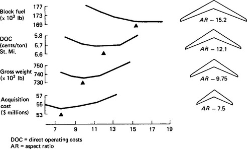
When fuel efficiency is the important design option, an aspect ratio of 10:1 to 15:1 would be efficacious, recognising that these are heavier wings. However, if ‘acquisition costs’ are important, then (at the other end of the scale) an aspect ratio of 7.5 would be appropriate. Clearly, there is no single ‘optimum’ aspect ratio that meets all criteria, so the designer must make an acceptable compromise. Aircraft weight and wing weight are important to the overall performance of an aeroplane so the designer’s objective is to achieve a maximum L/D ratio for a minimum wing weight. An integral part of this design activity centres on an evaluation of wing materials that yield the maximum strength-to-weight ratios. Other than this, composites (non-metallic materials) such as Kevlar (aramid and graphite), light-weight materials, such as new aluminium alloys, titanium, lithium alloys, etc., are candidates. Most composites have the advantage that double curvatures and unique aerofoil configurations can be fabricated, which are difficult to achieve with metallic structures.
The wing ‘aerofoil’ cross-section is another key aspect of wing performance and the wing camber must be such as to optimise the lift and suction forces across the wing. The important objective is to obtain a laminar airflow over as much of the wing as possible and to delay the break-up of airflow, which results in turbulence and drag. Addressing such wing designs, aerodynamicists have developed customised airfoil sections (such as used in ‘supercritical’ wings), whose distinctive aerofoil section keeps the airflow laminar, over much of the wing’s forward cross-section. Complementary to this, the designers have evaluated and developed ‘natural’ and ‘forced’ techniques of laminar flow control. In the former case, natural laminar flow is accomplished by an efficient wing-camber design, such as the ‘supercritical wing’. With forced laminar flow control, a complex wing manufacturing design is involved in which slots or small openings are fabricated in the wings to permit the wing’s boundary air to be sucked close to the wings, by means of ‘suction air’ derived from engine compressor bleed air.
Wing design is a key to fuel efficiency. Figure 47.2 shows a comparison of an early wing design and an ‘advanced’ wing design; the latter is derived from computer modelling, wind-tunnel testing, etc. The curves show that the advanced wing design yields a 11–12% improvement in fuel consumption (at the 25% and 40% positions of the wing’s mean aerodynamic chord (m.a.c.)). Furthermore, as the centre of gravity (c.g.) moves aft of these neutral points, another 1.5–3.0% improvement can be achieved. However, when the c.g. travels to 35% m.a.c., it reaches a point of relaxed static stability (r.s.s.) and, further back, to a point of ‘negative’ static stability, where the aircraft becomes longitudinally unstable. In this condition, the pilot cannot fly the aeroplane manually and must rely on a sophisticated (and highly reliable) stability augmentation system (s.a.s.). This type of system dictates the adoption of an electronic flight control system, known as a digital flight control system (d.f.c.s.). Apart from providing stable flight management (of a basically unstable aircraft), the primary function of the d.f.c.s. is to reduce the trim drag on the tail of the aeroplane. This trim drag is due to a down force on the tail, when the c.g. of the aeroplane is forward of the wing’s m.a.c. and it results in a fuel penalty.

47.4 Integrated active controls
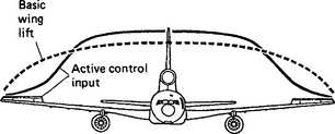
A fall-out ‘benefit’ from the adoption of a sophisticated d.f.c.s., is a reduction in wing weight which can be achieved by the use of integrated active controls (i.a.c.s). Active control technology (a.c.t.) involves a duplicative use of the ailerons, such that the ailerons can be operated symmetrically in addition to their normal (differential) mode of operation. The purpose of a.c.t. is to modify the spanwise wing-lift distribution from the wing root out to the wing tip. Normally, the spanwise wing-lift distribution is elliptical as shown in Figure 47.3, but when a.c.t. is used the wing-lift distribution is reshaped as indicated. This results in a reduction in the wing-root bending moment, to permit either a lower weight wing design or a wing design with a higher aspect ratio. Lockheed opted for the latter in the L-1011 aeroplane and added a 3.2 ft extension on each wing to achieve a higher aspect ratio wing and a more fuel-efficient aeroplane.
In summary, it is clear that aircraft designers have kept up with engine designers and have taken advantage of minimum-weight materials (and composites) to achieve efficient aerofoil designs. These physical changes, when combined with the use of a.c.t., have enabled the aeroplanes to operate in regions of r.s.s. and so achieve improved fuel efficiency (see Figure 47.2). When a.c.t. is applied to the three axes of the aeroplane it affords fuel-saving benefits. The Boeing B-757/769, Douglas MD-11 and the Airbus Industrie A-310/A-330 series (and other aircraft) exemplify the application of sophisticated flight-control systems.
47.5 Flight-control systems
Historically, the flight-control surfaces in early aircraft were operated directly by mechanical control cables (or torque tubes) running between the control stick and the surfaces. Such mechanical controls were in fact still used on modern aircraft such as the Lockheed L-1011. These systems though reliable are mechanically complex, as they involve many bell cranks, walking beams and differential levers, etc. The complexity of the design, the close manufacturing tolerances and the necessary adjustments (to minimise backlash problems, etc.) characterise this as a high maintenance support flight-control system. Given the prospective obsolescence of such mechanical systems, the aerospace industry moved to the adoption of electric/electronic flight-control systems based on the use of fly-by-wire (f.b.w.) and power-by-wire (p.b.w.) systems.
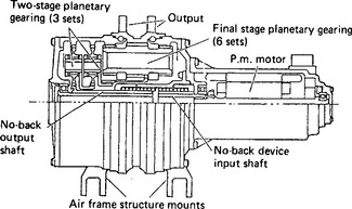
In a f.b.w. system, triple or quadruple redundant computers transmit a serial digital bit stream to the power electronics of the remote f.c.s. actuators, which operate the control surfaces. A block diagram of a typical f.b.w./p.b.w. system is shown in Figure 47.4: the actuators can be duplex hydraulic jacks, electric or electrohydraulic. A view of a typical rotary electric actuator shown in Figure 47.5 is used for spoilers.

Early f.b.w. systems used analogue data transmission and they go back to the early applications in the Mercury Space Vehicle (1960) and the XV-4B experimental aeroplane (in the mid-1960s): the US Air Force F-8 (1974) was the first aeroplane to adopt a digital flight control system (d.f.c.s.) (see Figure 47.6).

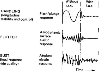
As discussed in Section 47.3, modern d.f.c.s.s brought to commercial and military aeroplanes benefits that were not possible with mechanical control systems. In addition to the ability to fly unstable aircraft, i.a.c.s provided better ‘ride quality’, eliminated (or damped) incipient wing-flutter conditions and allowed the aeroplane to fly through strong gust conditions without structural damage (Figure 47.7). Computerised flight control (with different flight options) also became possible and autoland systems were implemented that could meet the FAA’s (Federal Aviation Association) category IIIb/IIIc class conditions for landings in low-visibility conditions.
In the military aeroplane, manoeuvre load control (m.l.c.) is a feature that can be added to the d.f.c.s. and this enables the pilot to pull high g forces, during tight combat manoeuvres, without exceeding the vehicle’s structural load limits. The d.f.c.s. also provides superior flight-management features in high-performance aircraft, which use interactive engine/f.c.s. controls. In these aircraft, the engine’s two-dimensional thrust-vectoring system complements the flight-surface controls. The engine’s sophisticated management system is typically effected via a computerised full authority digital electronic control system. These technologies are key to the complex control and flight management of aircraft such as the Harrier, AV-8A and other sophisticated aircraft.
47.6 Systems technology
Whilst an aeroplane’s performance and operation are strongly tied to the engine, wing and f.c.s. technologies, the aeroplane is also strongly dependent on systems technology. As an aeroplane’s ‘propulsor system’ is its ‘primary’ power source, the systems are defined as the secondary power system and they consist primarily of:
As associative (dependent) parts of these ‘power-source’ systems, there are ‘utility’ or ‘subsystems’ such as the environmental control system, landing gear system, nose gear steering system, thrust reversing/wheel braking system, hydraulic, pneumatic and electric systems. These subsystems all extract power from the propulsor system (in pneumatic, hydraulic or electric form).
In a turbojet aeroplane, pneumatic power is extracted from the engine’s compressor via annular ‘taps’ at the mid and last stages of the compressor. This high-pressure high-temperature air is then used typically for ‘hot-wing’ deicing, where hot pressurised air is injected into a double-wall leading edge via ‘piccolo’ tubes and manifolds with ‘stub outs’. Engine deicing and engine starting are also normally powered by engine bleed air.
Pressurisation and cooling of the cabin/cockpit air-conditioning system are normally accomplished with bleed air by ducting the air from the power plants up to the flight station, where ‘air-cycle packs’ are located. Each of these packs comprises a bleed-air-powered turbine which drives the compressor (mounted on the same shaft) and at the same time provides expansion cooling as the air passes through the turbine. The air-cycle pack is lightweight and compact, because the turbo machinery runs on air-foil bearings at speeds of 80000 to 100 000 rev/min.
In addition to providing bleed-air power, the engine normally has a ‘waist-section’ gearbox (located at the 60/C position) which provides multiple output (flange) pads to drive fuel/lube pumps, hydraulic pumps and electric generators. The engine gearbox also typically carries a pneumatic starter. Figure 47.8 shows a typical transition from a conventional accessory gearbox to an all-electric configuration using an integrated engine generator/starter.

Figure 47.8 Secondary power system transition. E.l.p. engine lube pump; f.c., fuel control; f.p., fuel pump; u.h.p., utility hydrogen pump; i.d.g., integrated drive generator; p.s., pneumatic str.; e.d.c., engine driven component; h.p.r., hydraulic-pump rotor; h.p.t., hydraulic-pump turbine; i.e.g./s., integrated engine generator/str.; p.t.o., power take-off; v.s.c.f., variable speed constant frequency; a.p.u., auxiliary power unit
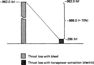
A typical accessory gearbox configuration is that mounted on the Rolls-Royce RB.211 engine. This is of a novel modular design, being driven by a power shaft from the high-pressure spool. The accessory gearbox and its accessories are typically cooled by engine-driven oil-lube pumps. The Rolls-Royce RB.211 is classified as a ‘high bypass’ turbofan engine which is able to furnish low and high pressure bleed-air; however, at high altitudes (35 000 to 42 000 ft) the engine core flow is much decreased, compared to low-altitude core flows. In a large commercial aeroplane carrying 300–400 passengers, there is a large e.c.s. bleed-air demand that, unfortunately, remains constant up to the high altitude and, thereby, creates an unfavourable fuel penalty. In contradistinction to this, if the e.c.s. were powered electrically the fuel penalty would only be some 25% of the bleed-air penalty. The difference between the thrust loss as applicable to the RB.211 in a commercial transport aircraft such as a Lockheed L-1011 or a McDonnell-Douglas DC-10 is shown graphically in Figure 47.9.
47.7 Hydraulic systems
Almost without exception, hydraulic systems (in past and current aircraft) used direct or indirect, engine-driven pumps that were typically of the constant-pressure/variable-displacement type. These pumps operated with delivery pressures of 3000, 5000 or 8000 lb/in2 and at typical flow rates of 5–65 gallons per minute (gpm). The pumps normally have good efficiency (80–85%) at high flow rates, but at low flow rates, the efficiency falls off sharply. Therefore, under conditions when the flaps, spoilers, slats and landing gear have all operated (and the aircraft is in cruise flight) the fluid demand is very low, but the pumps still deliver some 92% of the take-off flow rate; consequently, there is a major mismatch between supply and demand! Another problem with conventional hydraulic systems is that the pumps exhibit constant heat dissipation, regardless of the flow rates (Figure 47.10). As a result, a comprehensive oil-to-fuel thermal management system is required.

Hydraulic systems are, in the main, complex labour-intensive systems that comprise accumulators, reservoirs, pressure regulators, filters, noise attenuators and other fittings; but it is the ‘distributed’ hydraulic system that introduces the main problems of hydraulic systems because of leakage and contamination problems associated with the use of long fluidic lines.
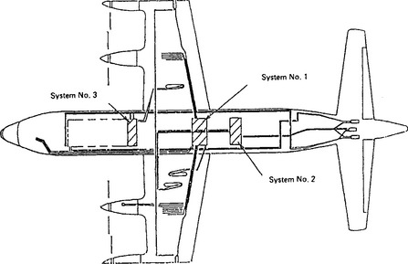
In the majority of aircraft, the sources of hydraulic fluid power are typically pumps driven off the engine’s accessory gearbox or off air-frame mounted accessory drives (see below). The latter are normally associated with high performance, small aircraft and their characteristics are discussed later in this text. In a centralised hydraulic system, one or more ‘hydraulic load centres’ are set up in the aircraft and the engine pumps feed into these load centres from which the hydraulic power is then distributed to the hydraulic loads (flaps, slats, landing gears, etc.). A multiple load-centre configuration, as used in the Lockheed P-7A ASW aeroplane, is shown in Figure 47.11.
In both these systems, many, many high-pressure (3000, 5000 or 8000 lb/in2) lines thread their way through the aircraft creating a difficult physical installation. Also, because of vibration, the line joints are exposed to incipient leakage problems and, in military aircraft, to prospective fire hazards when missiles penetrate the aeroplane. The facts, nonetheless, are that hydraulic systems have a significant historical record of reliability over 40 years, and it is difficult to compete with the simplicity of a duplex (double piston) hydraulic jack. Furthermore, it is only recently that electrics could be used to take over the hydraulic functions such as landing gears, and the more sophisticated loads associated with the aircraft’s primary/secondary flight-control surfaces. A new trend, however, has now been established under the umbrella of the US Airforce/WRDC MEL programme, which could lead to the use of electrohydraulic and electric actuators (see later sections). A typical two-channel hydraulic configuration is shown schematically in Figure 47.12.

47.8 Air-frame mounted accessory drives
The secondary power system normally comprises direct engine-driven electric generators (or integrated drive generators (i.d.g.s)) and hydraulic pumps. These accessories are typically mounted on a ‘waist-section’ accessory gearbox (a.g.b.) normally located at the 60/C position on the engine. On the Lockheed L-1011 aeroplane all the accessories such as the engine lube/fuel pumps, tachogenerators, generators and hydraulic pumps are driven by this gearbox. However, in advanced performance aircraft, such as the US Air Force YF-22 and YF-23 aeroplanes, two air-frame mounted accessory drives (a.m.a.d.s) are remotely driven (via dis-connectable drive shafts) and the secondary power system components are mounted on these gearboxes.
The reason for the a.m.a.d. configuration in the advanced technology fighters (a.t.f.s) is that these aircraft are committed to high sortie rates (and short turn-round times) and these objectives cannot be met with hydraulic pumps mounted directly on the engines. A.m.a.d.s were therefore the practical alternative, since they could be mechanically isolated when the engines were dropped from the aeroplane. This also avoided the prospective leakage and contamination problem that occurs when hydraulic lines are opened up. The a.m.a.d.s tend to be a legacy of the flight controls and, as shown in Figure 47.13, they are a complex, heavy, costly addition to the aeroplane. In addition, a.m.a.d.s decrease mission reliability and abrogate the possibility of achieving low maintenance-support objectives. Another problem with a large-capacity system using say four 156 fhp pumps is the constant heat dissipation which requires a dedicated oil-to-fuel heat exchanger to absorb the approximate 5800 British thermal units (Btu)/min heat losses: this is equivalent to about six 5 ton air conditioners!

Figure 47.13 Comparison of a.m.a.d. and electric secondary power systems. a.m.a.d., Air-frame mounted accessory drive; d.c, disconnect coupling (engine); e.c.s., environmental control system; h.p., hydraulic pump; v.s.c.f., variable speed constant frequency; a.t.m., air turbine motor; a.g.b., accessory gearbox; e.a.c.p., electric air cycle pack; a.p.u., auxiliary power unit; c.f.g., constant frequency generator; r.a.t., ram air turbine; e.m., electric motor; I.c., load compressor; s.m.,…; v.f.g Engines are turbojet/turboshaft engines
In addition to the hydraulic pumps (and a variable speed, constant frequency (v.s.c.f.) generator), each a.m.a.d. carries an air turbine motor, which is used for ground and emergency flight operation. As shown, the aircraft’s auxiliary power unit (a.p.u.) is interfaced with the a.m.a.d.s via pneumatic ducts. The a.p.u. also has an electric starter and a gearbox, on which are mounted a hydraulic pump, electric generator and a compressor. The compressor provides hot pressurised air (at approximately 52 lb/in2) that can be selectively routed to either a.m.a.d. to permit running and checking of the a.m.a.d.s. The a.p.u. can also be operated in flight in the event of a single or dual engine ‘flame-out’. In the YF-22/YF-23, there is almost critical dependence on an in-flight operation of the a.p.u., since the a.t.f.s are able to operate in regimes of aerodynamic instability. The a.p.u. also has an important ground-operation role, providing the a.t.f.s with power autonomy when they are dispersed at remote bare sites around an airfield.
In summary, a.m.a.d.s are a result of the selection of hydraulic flight controls; but with the trend to ‘more electric’ (m.e.l.) aircraft and the use of electric flight controls, electric (starter) generators could be the only components mounted on the engines. These generators however, could power electro-hydraulic and other advanced flight-control actuators in addition to the aircraft electrical and electronic systems.
47.9 Electrohydraulic flight controls
Electrohydraulic flight control units were used in the Vickers VC-10 (commercial transport) in the 1960s and each consisted of a compact integration of a motor pump, a servo-control, a self-contained fluid, etc. A total of 11 units were used in that aeroplane; four aileron units, four elevator units, and three rudder units. Two units in each group incorporated an integral autostabiliser/autopilot control consisting of an electrical torque motor, operating on electric signalling. These primary flight controls were operated successfully and they complemented the three spoilers in each wing, which provided air-brakes, direct lift control and back up for the ailerons.
Recognising the major technology improvements that have taken place since the 1960s, e.h.a.s are now a low-risk technology. Also, many international companies produce a variety of electrohydraulic actuators. Some employ a constant speed/variable displacement/bidirectional pump or a constant-speed pump operating with a servo-valve control. More recently, however, an ‘electrohydrostatic’ actuator was developed which operates uniquely as a ‘pressure-on-demand’ actuator with low heat losses (Figure 47.14). A US company, H. R. Textron, California, also offers a novel actuator design which uses dual hydraulic jacks to impart a rotary via a high-lead-angle ball screw jack.

47.10 Electromechanical flight controls
Electromechanical actuators (e.m.a.s), like e.h.a.s, are attractive candidates for the new flight-control systems since they offer the same operational flexibility and advantages as e.h.a.s. In addition, losses in the motors and electronics decrease at light loads and e.m.a.s only dissipate high heat during the brief periods of high hinge moments. In an e.m.a. the motor current is proportional to torque:
where T is the motor torque, ϕ is the stator flux, IA is the rotor current, and cos θ is the motor power factor.
Typically, the preferred implementation of an e.m.a. is a motor-driven ‘power hinge’ using a relatively high speed motor driving a ‘power hinge’ (attached to the control surface) via a planetary reduction gear train. However, linear e.m.a.s using high-efficiency ball screw jacks have also been used and, where high mechanical loads were present, the French-designed ‘transrol’ actuator offered advantages. In the field of novel actuators technology a US designed ‘eccentuator’ is of note. This utilises a ‘bent shaft’ which is rotated while its drive end (located in a ‘carrier’) is rotated in the opposite direction, so as to yield a planar output (Figure 47.15).

Figure 47.15 An eccentuator. The eccentuator motion compensates for the lateral displacement while doubling the output power. T.e., trailing edge θ, Beam bend angle; c.w., clockwise; c.c.w. counter clockwise.
With digital flight-control systems (f.c.s.) tri- or quadric-redundant computers transmit a digital bit-stream which contains rate, surface-displacement and directional information to the power electronics modules, that control electric actuators. Passive stabilisation networks, loop closure signals, etc., provide the necessary stability and performance characteristics of the actuators. The e.m.a.s provide high static/dynamic stiffness and bandwidth response, comparable with the best hydraulic actuators.
As an example of e.m.a. status, a ‘motor controller’ design by General Electric for a 12 hp actuator has dimensions of approximately 1 in × 3 in × 6 in. These modules actually integrate low and high voltage chips on the same substrate and they interface directly with a 1553B type digital data bus.
With the adoption of electric flight controls and other electric technologies, there ensues a major simplification of the aeroplane, due to the elimination of the labour-intensive (distributed) hydraulic systems and the elimination of the untenable practice of bleeding the engine compressors for high-pressure high-temperature pneumatic power.
47.11 Aircraft electric power
In World War II, the electric demands of the large four-engine bombers were met by four 28 V d.c. 6kW generators which supplied the power demands of some highly electrified aircraft using electric turrets, electric de-icing, and nominally large electric/avionic systems. In the immediate post-World War II phase (1946 onwards), the aerospace industry realised that these low-voltage d.c. systems could no longer meet the projected future demands for electric power, so Advisory Boards were set up (in the USA and the UK) to evaluate higher voltage, higher power electric systems. These systems were premised on the use of higher d.c. voltages of 112, 240 and 340 V and higher a.c. voltages of 120 to 400 V; based on frequencies of 250, 400, 800 Hz and above.
However, the trend was towards a.c. power systems because of their ability to transform voltages, the ease of power switching a.c. currents, and the availability of highly reliable, rugged squirrel-cage induction motors. The three-phase, 200 V, 400 Hz system therefore became the popular choice and was selected by the author for the Bristol Brabazon I, Mark I aeroplane; a very large commercial aeroplane, designed for cross-Atlantic operation. The Mark I aeroplane was powered by eight Centaurus 2800 bhp (internal combustion) sleeve-valve engines buried in the wings. The later Mark II aeroplane was slated to use eight 3500 shp Proteus turboprop engines, but the Brabazon Mark II was not brought into prototype flying status. Both the Mark I and Mark II aircraft were configured with four pairs of engines, each pair driving two Rotol contra-rotating propellers, driven from a propeller reduction gearbox.
The electric system in the Brabazon I, Mark I, was probably the first major a.c. power system in the world and it consisted of six 40 kV-A Rotax a.c. generators and two Rotol 40 kV-A auxiliary power units (a.p.u.s).1 A companion large-aircraft programme was the Saunders-Roe Princess Flying Boat which was to be powered by 10 Proteus engines. Uniquely, the electric system was designed around a 250 Hz system, using a.p.u.s rather than engine-driven generators. A variety of electric power systems were therefore evaluated in those early post-World War II years, but the trend was strongly established for three-phase 400 Hz a.c. power in the military and commercial aircraft. Constant speed hydromechanical drives and the later integrated drive generators (by Sundstrand) dominated the electric systems in these post-World War II aircraft and these transmissions furnished constant-frequency power over the variable-speed range of the engines. Other constant-speed drives were developed by General Electric and Lycoming. General Electric’s drive was based on a ‘ball pump’ configuration, while the Lycoming drive was designed around a roller/toroidal (mechanical) transmission. These drives, unfortunately, encountered some pervasive development problems and there was only limited production. The problems (characteristic to mechanical and hydromechanical drives), are the high Hertzian stresses, incident upon the use of back-to-back hydraulic motor pump units and the mechanical complexity.
In an attempt to offset the perceived problems of mechanical/hydromechanical drives, the aerospace electrical companies developed electronic approaches to generating constant-frequency power. These were known as variable speed constant frequency (v.s.c.f.) power systems and they were based on ‘cycloconverter’ and ‘d.c. link’ conversion techniques. These systems held the prospective advantages of higher efficiency and higher reliability; also they were able to take advantage of the burgeoning technology in power electronics and very large scale integrated (v.l.s.i.) chip technology.
Nonetheless, constant-speed hydromechanical drives and integrated drive generators remained the power systems of choice in modern aircraft, except for the new trend towards 270 V d.c. However, when large-capacity systems (300–500 kV-A) become necessary, a direct-driven generator, operating with a constant volt/cycle characteristic, could become an efficient and practical alternative. This would enable the generator to operate over a 2:1 speed ratio, without compromising its weight and size vis à vis an optimally sized constant-speed machine. In addition, since it would be desirable to use such a large generator to start the engines, the synchronous generator could be operated as a synchronous motor, deriving its power from a converter producing programmed voltage-to-frequency (V/F) power. Furthermore, once installed, the inverter/converter can be used for other purposes in the aeroplane. For example, a motor-driven e.c.s. pack could be driven at speeds of 80000 to 100 000 rev/min, permitting the use of ‘air-foil’ bearings, as used with bleed-air turbine/compressor units. For these speeds, a two-pole (low slip) induction motor would require a frequency of 1600 Hz for a speed of 94 000 rev/min, approximately.
Implicit in the adoption of a three-phase a.c. power system, operating with a constant volts per cycle voltage control, is the fact that the generator operates with a ‘power proportional speed’ characteristic. Thus, for the typical 2:1 speed range of the turbojet engine, the generator output would be reduced to 50% on the ground. There is, however, synergy in this because, in the real world, the generator would never be required to provide full power during ground operation since loads such as windshield heating, galley, wing/engine de-icing, the utility electric loads, and the avionic loads would never all be switched on at one time. Similarly, electrohydraulic pumps, landing gears, etc., would not be operating.
In contrast to the above, aircraft power generators in almost all aircraft today are effectively 2:1 oversized. For example, in the case of a generator designed to provide 270 V d.c. at 50% per unit (p.u.) speed, it ‘wants’ to produce 540 V at 1.0p.u. speed, but it is harnessed by the voltage regulator to 270 V. Also, when the 270 V d.c. is developed by rectifying the a.c. generator output by a three-phase full-wave silicon controlled rectifier (s.c.r.) bridge rectifier, only a small part of each (rectified) sine wave is used to produce the 270 V d.c; as shown in the lower half of Figure 47.16. There is the irony also that the bridge-rectifier/filtration components are only efficient on the ground, at 0.5 p.u. engine speed!

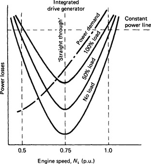
In the case of a hydromechanical transmission, the ‘speed penalty’ shows up as a ‘power mismatch’. As shown in Figure 47.17, the integrated drive generator can produce full power (at half speed), but the ground-power demand is very low. It is also of note that the parabolic (power) curves tend to be asymptotic at the 0.5 and 1.0 p.u. speeds, so the electrical, fluidic and mechanical losses tend to remain high at these point extremes.
47.12 Summary of power systems
Clearly, there is no panacea for the problems typical of the 2:1 speed range of turbojet engines, and this is somewhat unique to the aircraft power systems. In utility electric systems, steam turbines drive generators at constant speed, so they intrinsically produce constant voltage/constant frequency power. In contrast, the aerospace electrical engineer must resort to innovative approaches to meet the speed-range problem. Basically, the choices are:
None of the above is without some disadvantages with regard to costs, reliability, weight, efficiency, maintenance support, life-cycle costs, etc., but it is possible to draw on the expertise, resident in the above power generation systems to develop a simple ‘universal’ type power system that could furnish multiple, ‘dedicated’ power supplies for the different loads. One such system, shown in Figure 47.18 utilises a single high speed (direct driven) 500 kV-A generator, which can operate at a speed of 24 000, 36 000, or 48 000 rev/min. The figure shows a simplified scheme of a generator supplying three, or more, power supplies, such as:

Examples of such systems include the following.
(1) A Westinghouse 500 kV-A unit furnishing multiple and different characteristic outputs—120 kV-A of three-phase, 200V, 400Hz power; 270 kW, 13.2 kV d.c., 17 kW (pulsed load), 28 V d.c.
(2) An Allied Signal 500 kV-A generator with a weight of only 136 lb, when driven at a speed of 48 000 rev/min. This speed is somewhat high for a direct engine-driven generator, but it is suitable for a turbine drive.
The advantages offered by this hybrid system are that very high-capacity low-weight generators can directly power large loads such as landing gears, swing-wings, tilt-tails, de-icing systems, space-heating, lighting, utility loads, and (in commercial aircraft) galley loads. The dedicated loads such as 270 V d.c. and 28 V d.c. (and special high frequency power supplies) can be derived on an ‘as-required’ basis. However, with advanced power generation systems, in the 150–500kV-A per channel capacity, 3% or less conversion may be more than adequate for each of the dedicated power supplies. This, therefore, significantly reduces the required sizes of the power diodes/filters, etc., compared to the sizes required in a direct engine-driven 270 V d.c. generator. Difficulties in rupturing the prospectively high short-circuit currents and the heat dissipation of solid state power controllers would be a concern in such high voltage d.c systems.
In contrast, the selection of an a.c power system simplifies the switchgear problems and permits the use of transformers to provide multiple different voltages for windshields, props/spinners, etc Also, three-phase a.c. power permits the use of highly reliable, lightweight squirrel-cage induction motors for many loads such as electromechanical actuators, fuel/oil motor-pump units, passenger/cargo/weapon doors, hermetically sealed Freon compressors, motor-driven, bootstrap/air-cycle machines, etc.
Loads such as constant-pressure electrohydraulic pumps may be operated over a 2:1 (or more) speed range and still provide constant torque (Figure 47.19(a)), as demanded by 3000 or 5000 psi pumps. The efficiency-torque characteristics (Figure 47.19(b)) also show that the efficiencies remain high for the four V/F curves shown.

Figure 47.19 Performance of electrohydraulic pumps on constant V/F power: (a) speed-torque curves; (b) efficiency—torque curves
One of the problems with 270 V d.c. systems is that the 270 V d.c. motors cannot operate directly on 270 V d.c., so the d.c. voltage must be ‘inverted’ to power the three-phase a.c. stators of the many drive motors; ironically, these inverters would actually furnish constant V/F power!
47.13 Environmental control system
The environmental control system (e.c.s.), unlike many other services, represents an almost constant-horsepower demand over the complete flight envelope, regardless of engine power settings and engine speeds. This, in the past, has been a significant problem for the bleed-air system and it impacts on any mechanical power system, including an electrically powered e.c.s.
For a 500 passenger advanced transport aircraft (a.t.a.), the increased fuselage length, the larger number of windows, and the higher thermal transconductance all result in a significant increase in the capacity of the e.c.s. Without taking advantage of air recirculation (50% or more), the horsepower demand could be excessive. Therefore, it is axiomatic that a.t.a.s utilise a degree of air recirculation: the usual problems of doing this will be ameliorated by the prospectively lower level of vitiated air which can be expected, in the future, when there will be less nicotine contamination of the air. Also, improved filtration methods are now available.
Basically, the e.c.s. performs the following functions:
Typically, cabin altitude is maintained at 6000 ft, which is equivalent to about 11.8 lb/in2a. At normal cruise altitudes, an intermediate tap on the engine compressor supplies the pressurisation needs, but at idle descent letdown it is necessary to change over to a last-stage bleed. Duct pressures and temperatures near the bleed ports are typically 100–300 lb/in2a and 200–700°F. These higher pressures and temperatures are necessary, in conventional aircraft, where the hot pressurised air is used for wing anti-icing and for air-turbine motor drives. However, these temperatures and pressures are actually too high for the cabin e.c.s. requirements, so intercoolers and air cycle machinery are necessary to condition the air before it is introduced into the cabin. Outflow valves modulate to maintain the cabin pressure at the approximately 6000 ft altitude.
For all-electric e.c.s. (a.e.e.c.s.) pressurised air is derived from motor-driven compressors. For a typical 500 passenger a.t.a., the induction motor-driven compressors are designed to furnish approximately 1.2 ppm per passenger, made up of 300 ppm of fresh air and 300 ppm of recirculated air. The pressure ratio of each compressor is approximately 3.4:1, so the heat of compression can be used to supply the heat requirement during winter operation. The temperature rise across such compressors is defined as:
where Ta is the ambient temperature (in degrees Farenheit), PR is the pressure ratio, K is the ratio of the specific heats, and ηc is the compressor efficiency. Δ°F is temperature rise in degrees Fahrenheit.
The power to drive each compressor is given by
where ![]() is in pounds per second and ΔT is ΔF in equation (47.4).
is in pounds per second and ΔT is ΔF in equation (47.4).
Equations (47.4) and (47.5) show that the ΔT value for air across the compressors is approximately 225°F and the compressor power is approximately 120 hp. To avoid overloading the motor compressors during low-altitude, high engine speed conditions, the compressors incorporate an inlet-guide-vane control and a pole-changing motor, which changes speed from 48000 to 24000 rev/min nominal.
The cooling requirements can be furnished by three vapour-cycle cooling units, which employ a reverse-Rankine cycle with a R-114 refrigerant: the moisture content, which affects the capacity of the cooling system, was taken as 130 gr/lb. Condenser cooling is effected by fan-induced air flow on the ground, and ram air in-flight. Inlet-guide-vane control is used to modulate the Freon flow and cooling capacity during light-load conditions.
Cabin cooling is a major load on the ground, with a fully loaded aircraft and outside air temperatures at ≥100°F. The metabolic load of 476 passengers and 24 crew members, the solar input, and other internal heat dissipation factors add up to a total cooling load in excess of 375 000 Btu/h for the large a.t.a. In a conventional aeroplane such as the L-1011, cooling is derived from three air-cycle units, which are an integral part of three e.c.s. packs. To furnish this power on the ground, an a.p.u. driven compressor is used.
Cabin heating tends to be a less significant requirement than cooling in that there is still a demand for cooling, during high-altitude cruise when there is a maximum passenger complement. The heating demand therefore applies mainly to cold-day conditions with low passenger densities, i.e. low internal losses. Evidently, with bleed air, there is an adequate supply of hot air.
As is typical with industrial or commercial vapour-cycle cooling systems, the liquid R-114 is flashed to a cold two-phase low-pressure liquid gas system, as it flows through the expansion valve; this liquid gas is supplied to the evaporators (for cooling the motors driving the compressors).
While a minimum weight was not emphasised in this e.c.s. design, a 1500 lb weight saving was achieved by using an all-electric e.c.s. instead of a conventional bleed-air powered e.c.s.
Figure 47.20 shows an a.e.e.c.s. that is a power regenerative system which utilises ‘air cycle’ and ‘vapour cycle’ cooling. The former consists of an air-cycle pack in which a compressor and a turbine are driven at high speeds (75000–90000 rev/min) by a low-slip, squirrel-cage induction motor supplied with high frequency. This whole assembly runs on air-foil bearings to provide long life and reliability. The compressor employs an inlet guide vane to improve efficiency and to modulate the air mass flow through the single-stage centrifugal compressor. The turbine itself furnishes two functions: it offsets the amount of power supplied to the compressor by the electric motor and provides cold air to the cabin. As mentioned above, the purpose of the e.c.s. is to provide conditioned air to the cabin and passengers.

Figure 47.20 Electric e.c.s. with air cycle and vapour cooling. EM, electric motor; IGV, inlet guide vanes; C, compressor; T, turbine; SV, selector valve; VCCP, (electric) vapour cycle cooling pack; HX, heat exchanger; PRV, pressure regulating valve; CV, check valve; SCR, silicon controlled rectifier; EV, expansion valve
The simplified scheme given in Figure 47.20 shows the e.c.s. operating in a typical flight condition (at 35000 ft) where power ‘regeneration’ is effective. For example, at 35000 ft, the atmospheric pressure is 3.5 lb/in2 a and the cabin pressure (for 6000 ft equivalent altitude) is approximately 11.6 lb/in2: this is equivalent to a pressure ratio of 3.3:1. This pressure ratio is then effective across the turbine, as the cabin outflow air is dumped overboard (to modulate the 11.6 lb/in2 pressure). As the outflow air discharges through the turbine, it develops shaft power to offload the motor-compressor drive. (Note: this a.e.e.c.s. is shown operating as a 100% ‘fresh-air’ system, but it can utilise a 50% ‘recirculation’ system; if this were adopted, however, the power regeneration would be reduced by 50%.)
During hot-day ground operating conditions, the total cabin-heat load is very high, so in this mode the compressor and turbine are connected in series by changing the position of the selector valves. With the selector valves in this position some of the heat of compression is removed by the heat exchanger (HX1) and further heat is removed by the turbine: The actual drop in temperature across the turbine is determined using Equation (47.4). From the turbine, the air passes through a second air-to-air heat exchanger (HX2) and then through the Freon evaporator; the flow of Freon through the evaporator may be modulated in accord with the desired evaporator exit temperature (typically 40°F). In this ground operation mode, the pressure rise across the compressor is reduced in the same ratio as the pressure drop across the turbine. The air entering the cabin is, therefore, at the same pressure as the outside (14.7 lb/in2) and is discharged overboard with minor pressure loss. On cold winter days, electric heat may supplement the metabolic heat load of the passengers by passing fan-recirculated air over an electric heater, whose power-dissipation is varied by a silicon controlled rectifier.
47.14 Digital power/digital load management
Presently used aircraft are still flying with 1960-1975 electrical technology and very little design activity has taken place to bring electric systems into line with the digital avionic and engine management systems. The NASA and the US Air Force/Navy laboratories have long promoted advanced digital power systems that would interface with solid state power controllers (s.s.p.c.s), controlled and monitored by a ‘data handling system’. The US Navy Air Development Center (NADC) has also installed two A-7 mock-ups in their laboratories at Warminster and have successfully demonstrated the advantages of modern power management over conventional power management.
Another key objective of the NASA and US military services is to adopt a ‘distributed power bus’ system, which would simplify power distribution to the loads and constrain the power wires to the areas in which the loads are located. This technology also inhibits the ‘bus-proliferation’ problem, which is a legacy of the conventional radial power systems now used in aircraft. For example, power feeders typically route from the engine-located generators to a remote (forward fuselage) main electric load centre. Radial power feeders then feed back to remote areas where the power feeders originated!
In the advanced power distribution system, insulated power feeders traverse the wings and the fuselage. The concept is that in a four-engine four-generator configuration there are only four distributed buses. The feeders are also redundant, i.e. insulated/isolated quadri-redundant feeders route in the fuselage and two sets of feeders in each wing are interconnected by bus ties. The distribution system may be operated as a ‘closing-ring’ system in which, in an extended-emergency condition, any one generator can feed all bus sections (Figure 47.21).

Figure 47.21 Advanced power generation system with distributed buses. APU, auxiliary power unit; G, generator; DACB, distributed a.c. bus; BC, bus contactor; EP, external power contactor; AP, APU power contactor; BT, bus-tie/buss
In the implementation of such a distributed bus system, subfeeder taps are made into the buses (as they traverse past key load areas) and they are protected at the tap points: this is essential in order not to compromise the primary feeders. The key and enabling technology in this advanced power system is a digital power/digital-load management system (d.p./d.l.m.s.).
To preserve the philosophy of isolated quadri-redundant power supplies, the generator channels are not paralleled. In addition, the health and status of each generator is monitored by a microprocessor-based generator control unit (Figure 47.22) that communicates with the flight station computer display unit over a 1553B, or other dedicated digital data bus (Figure 47.23). In addition to the management of the individual power channels, the d.p./d.l.m.s. controls the bus ties and the interfaces with the external/a.p.u. power systems.

Figure 47.22 Advanced power generation system with microprocessor control. BIU, bus interface unit; μP, (generator) microprocessor; G, generator; A, B, C, D, generator power contactors; DACB, distributed a.c. bus; DLMS, digital/power load management system; LMD, load management distribution; F/S, (flight station); E to J, contactors; N, neutral

Figure 47.23 DP/LMS Configuration (Leach designed alternative). The electrical system is reconfigurable to ensure that the mission is completed
Figure 47.24 shows a simplified scheme of the d.p./d.l.m.s. management system designed by the Leach Corporation. The electric load management centre (e.l.m.c.) interfaces with the 1553B bus and a MIL-STD-1750 processor (with a 128k word memory) manages the complete electric system via a dedicated load management distribution bus. This bus interconnects the ‘remote power modules’ (similar to the one identified in the e.l.m.c.) to control the ON/OFF status of the s.s.p.c.s and the smart remote power contactors (s.r.p.c.s).

The digital load management system makes possible the control of all loads via the distributed bus system and discrete (multi-bit) address code and a logic code. This code also ensures that the s.s.p.c. closes only when all the circuit parameters are correct. In addition, the individual loads are given a ‘priority tag’ which establishes their level of importance in the overall hierarchical structure of the loads in the aeroplane. Loads may therefore be in, say, four levels; in which loads in group 1 would be first isolated, followed by those in groups 2, 3 and 4, as the level of emergency increases. For example, if smoke occurs in the vehicle, all four groups would be disconnected, leaving only the flight-essential loads connected. From this, it is clear that power reduction is effected not by dropping dedicated buses, but by a software-controlled dumping of individual loads.
The s.s.p.c./s.r.p.c. combines the features of a relay and a circuit-breaker but, unlike circuit-breakers, they can detect open-circuit and open-phase faults. By the use of the d.p./d.l.m.s., multiple circuit-breaker panels are eliminated and there is a significant reduction in the amount of load wiring.