
Protection
35.1 Overcurrent and earth leakage protection
The main effects of fault current in a power system are:
(1) disturbance of the connected load;
(2) overheating at the fault point and in associated plant;
(3) electromagnetic forces of abnormal magnitude, with consequent mechanical damage; and
The function of the protective equipment is to isolate the faulty plant from the running system by initiating tripping signals for appropriate circuit-breakers. It should therefore discriminate between faulty plant and sound plant carrying through-fault current. The whole process must be effected with the minimum of delay and disturbance.
Exceptionally, some faults may be allowed to persist: an example is an earth fault on a system earthed through an arc suppression (Petersen) coil, or one having an isolated neutral, where the fault may be located and alternative feeds provided before the fault is isolated.
Faults are due to insulation breakdown by deterioration, overvoltage, mechanical damage or short-circuit effects; they may be simple or complicated, and involve conductor breakage or short-circuited turns on transformers or generators.
The incidence of faults on cables and lines depends on the installation and the climatic conditions. For a typical system in a temperate zone the distribution of faults as percentages of the total is approximately: overhead lines, 60; cables, 15; transformers, 12; switchgear, 13. The causes of overhead-line faults, and the number of faults per 100 km of line per year, are, typically: lightning, 1.0; gales, 0.15; fog and frost, 0.1; snow and ice, 0.06; salt spray, 0.06. The total is 1.37 faults per 100 km per year: in tropical countries lightning faults may be markedly more numerous. In general, the higher the voltage the lower the number of lightning faults.
35.1.1 Fault conditions
Below are given circuit and phasor diagrams relevant to the behaviour of protective equipment under the simpler fault conditions.
35.1.1.1 Three-phase fault
A three-phase fault usually develops first as a phase-earth fault, and it may be unbalanced. Even when a circuit-breaker closes on to a three-phase fault, one phase may momentarily be faulted before the other two, a matter of importance in high speed protection. Figure 35.1 shows the relevant phasor diagram. At the fault the voltages to neutral are zero; and if AN, BN, CN are the phase-to-neutral pre-fault voltages, the voltages at some distance from the fault (e.g. at a relay controlling a circuit-breaker) are A′N, B′N, C′N. With a symmetrical short-circuit the conditions are independent of the system earthing arrangements.

35.1.1.2 Phase-to-phase fault
Two phases are faulted clear of earth, an unusual kind of fault even less likely on cables than on overhead lines. Figure 35.2 shows AN, BN and CN as the normal voltages at the site of the fault. On occurrence of the fault, the voltages there are XN, XN and CN, and the voltages at some specified distance are A′N, B′N and C′N, with the locus of A′ and B′ on the line AB. The voltage to earth of the sound phase is not affected. The conditions are independent of the system earthing, but the fault current will be reflected into the further sides of associated transformers in accordance with their connections.

35.1.1.3 Single phase-to-earth fault
This type of fault is considered for a system with the generator or transformer having its neutral earthed (a) solidly, (b) through a reactor, (c) through a resistor.
Neutral solidly earthed: The voltages to earth at the point of fault with phase A earthed are zero, B′E and C′E, as in Figure 35.3, and at some distance away the voltages are A′E′, B′E′ and C′E′. The locus of A′ of the line AN, and the voltages to earth of the sound phases are slightly changed to B′E and C′E by reason of the currents in these phases between the two infeeds. With the system earthed at one point only (apart from the fault), the total earth fault current divides between the two infeeds. If there are two (or more) system earth points and the infeeds are IA and I′A, there may be currents in the sound phases of direction decided by the preponderance of zero-over positive- and negative-sequence impedance of one infeed compared with the other. In this case the residual or earth current on each side wil be IA + IB+ IC = IE; the residual voltage will be 0 + B′E + C′E at the fault, and A′E′ + B′E′ + C′E′ some distance away.

Earthed through reactor: With a low-valued phasor (small compared with an arc suppression coil), the earth point potential on the occurrence of a fault will be E (Figure 35.4(a)), and the drop in the reactor will be E′N. The fault position voltages are zero; voltages to earth of the sound phases are increased. If the reactor is an arc suppression coil, point E is raised to A, the sound phase voltages to earth become ![]() times normal, and the residual voltage at the fault will be 3 times the normal phase-to-neutral value.
times normal, and the residual voltage at the fault will be 3 times the normal phase-to-neutral value.
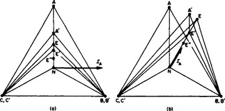
Earthed through resistor: The conditions (Figure 35.4(b)) are essentially similar to those for reactor earthing except that there is unbalance in the voltages to earth of the sound phases. The volt drop across the resistor is E″N.
35.1.1.4 Double phase-to-earth fault
With solid earthing at one point only, the voltages to earth at a double phase-to-earth fault will, as shown in Figure 35.5, be zero, zero and C′E, and at some distance away will be A′E′, B′E′ and C′E′. The voltage to earth of the sound phase may be increased at the point of fault. The angle α between the phase currents IA and IB (or IA and I′g) may be less than 60°, depending on the ratio of balanced to zero-sequence impedance; the angle varies considerably, according to the earthing arrangements, and in the limit with the neutral point isolated it becomes 180°. The residual current (i.e. the earth current) is the vector sum of the currents in the faulted phases and that (if any) in the sound phase. The residual voltage at the point of fault is the normal phase-to-neutral voltage, and it decreases with distance from the fault position.

With the system neutral earthed through a low-valued reactor, the drop across the latter is NE′ and the voltage to earth of the sound phase is CE, increasing to a possible maximum of 1.5 times normal value if the reactor is an arc suppression coil.
With system earthing through a resistor, the point E in Figure 35.5 is no longer on the line CX.
The system Z0/Z1 ratio is defined as the ratio of zero sequence and positive sequence impedances viewed from the fault. It is a variable ratio dependent on the method of earthing, fault position and system operating arrangement. When assessing the distribution of residual quantities through a system, it is convenient to use the fault point as the reference, as it is the point of injection of unbalanced quantities into the system. The residual voltage is measured in relation to the normal phase-neutral system voltage, and the residual current is compared with the three-phase fault current at the fault point. It can be shown that the character of these quantities can be expressed in terms of the ratio Z0/Z1 of the system; see Figure 35.6. The residual current in any part of the system can be obtained by multiplying the current from the curve by the appropriate zero sequence distribution factor. Similarly, the residual voltage is calculated by subtracting from the voltage curve three times the zero sequence drop between the measuring point in the system and the fault.

35.1.2 Protective equipment
The satisfactory operation of protective equipment (which extends from simple domestic subcircuit fuses to sophisticated electronic system devices) depends largely on co-ordination. The influencing factors include the network layout and characteristics, fault megavolt-ampere levels, earthing, the availability of pilot cables and the physical extent of the system. Generally, the higher the voltage and fault levels the more necessary is quick-acting discriminative protection covering lines and plant.
Protective equipment may be broadly classified into: (a) restricted zone, giving full discrimination; (b) semi-restricted zone; and (c) unrestricted zone, with no discrimination. Type (a) can be considered as applying to a network of such magnitude that the disconnection of each item of plant is necessary if an internal fault develops. Types (b) and (c) apply to less important installations and also as ‘back-up’ in restricted-zone schemes.
35.1.2.1 Modes of operation
An alternative classification based on the operating mode is as follows.
Overcurrent equipment operates if the current exceeds a pre-set value. Restrictions regarding the direction of the overcurrent are often included to improve discrimination.
Balanced (differential) equipment operates if an out-of-balance occurs between currents or voltages which under normal conditions are balanced.
Distance (impedance) equipment operates if the impedance (proportional to distance), as viewed at a circuit-breaker supplying a feeder, falls below a specified value.
35.1.2.2 Equipment elements
The chief items of plant making up a complete protective installation are as follows.
Current and voltage transformers: These provide convenient levels of current or voltage proportional to the system values. Rated secondary values are normally 1 or 5 A (current transformer (c.t.)), and 110V (voltage transformer (v.t.)).
Relays: These, operating from c.t. and v.t. detect the presence of faults and energise the trip circuits of the appropriate circuit-breakers. Electronic (solid state) devices are now generally available as alternatives to the electromagnetic types, and give improved performance.
Pilot circuits: These carry signals between points in the system for comparison, for feeder protection and other purposes. The circuits may be provided in a variety of ways:
(1) conductors specially installed for the purpose;
(2) rented telecommunication lines; the current and voltage limitations are 60 mA and 130 V peak, and the pilots must be insulated from all power system equipment for 15 kV;
(3) power transmission lines, using carrier signals at frequencies between 70 and 700 kHz;
(4) radio links using microwave transmission between line-of-sight terminals; and
The choice requires very careful consideration, particularly for long distances. Even apparently simple conductors, for which the resistance and capacitance between ends can be measured, often act as a transmission line operating in conjunction with relay equipment. The performance of the pilot circuit may be complex, and in operation is made even more so by inductive interference effects.
It is possible to obtain high-speed feeder protective schemes using voice frequencies of 600–3000 Hz, which are suitable for pilot-wire channels, or pilot-line carrier or radio channels.
The overall fault clearance time is made up of the signalling time, and the operating times of the protection relay, trip relay and circuit-breaker opening. This total time must be less than the maximum for which the fault can remain on the system for minimum plant damage, loss of stability, etc. In recent years practical minimum times have been achieved in reducing protection times from 60 to 20 ms, trip relay times from 10 to 3 ms, circuit-breaker times from 60 to 40 ms, leaving protection signalling times to be reduced from 70–180 ms down to 15–40 ms in the UK, and to 5 ms in certain parts of the world where system stability is critical.
Protection current transformers may have to maintain accuracy up to 30 per unit overcurrent, although often the error is less important than that c.t. characteristics should match.
Current transformers: The errors are due to the exciting current, and they vary with the phase angle of the secondary burden. An increased burden demands a corresponding increase in core flux, and as the exciting current is a nonlinear function of the flux, it is subject to a more than proportional rise accompanied by a greater harmonic content, so that the composite error is increased.
Protective equipment is intended to respond to fault conditions, and is for this reason required to function at current values above the normal current rating. Current transformers for this application must retain a reasonable accuracy up to the largest relevant current, known as the ‘accuracy limit current’, expressed in primary or equivalent secondary terms. The ratio between the accuracy limit current and the normal rated current is known as the ‘accuracy limit factor’. Standard values are 5, 10, 15, 20 and 30. Protective c.t. ratings are expressed in terms of rated burden, class and accuracy limit factor (e.g. 10 V-A class 10P 10). Classes 5P and 10P are useful only for overcurrent protection; for earth fault protection, in particular, it is better to refer directly to the maximum useful e.m.f. which can be obtained from the c.t. In this context the ‘knee point’ of the excitation curve is defined as that point at which a further increase of 10% secondary e.m.f. would require an increment of exciting current of 50%. Such current transformers are designated class X.
Current transformers may have primaries wound or of bar (‘single-turn’) form for mounting on bushings. For high-voltage systems the c.t.s may be separately mounted with oil or SF6 insulation.
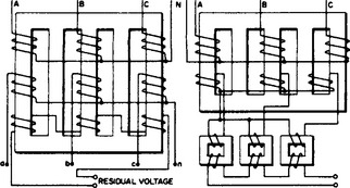
Voltage transformers: The main requirement in protection is that the secondary voltage should be a true reflection of the primary voltage under all conditions of fault. It is usual with electromagnetic v.t.s to apply additional delta-connected windings (Figure 35.7) to give a measure of the residual voltage at the point of connection. The three voltages of a balanced system summate to zero, but this is not so when the system is subject to a single-phase earth fault. The residual voltage in this case is of great value for protective gear practice as a means of detecting or discriminating between earth fault conditions. The residual voltage of a system is measured by connecting the primary windings of a three-phase v.t. between the three phases and earth, and connecting the secondary windings in series or ‘open delta’. The residual voltage is three times the zero sequence voltage. To measure this component it is necessary for a zero sequence flux to be set up in the v.t., and for this to be possible there must be a return path for the resultant summated flux: the v.t. core must have unwound limbs linking the yokes (Figure 35.7). If three single-phase units are used (as is common for e.h.v. systems), each phase unit has a core with a closed magnetic circuit, so that the above consideration does not arise.
An alternative, avoiding the cost of a HV voltage transformer, is to use the secondary voltages from a.v.t. on the LV side of a power transformer, the voltage drops in which are compensated by the addition or subtraction of voltages developed by c.t.s in the delta of the power transformer. The v.t.s and c.t.s must be provided with tappings if the power transformer is equipped with tap-changing gear, and arranged for automatic selection with the main tappings.
For high-voltage systems the capacitor voltage divider gives a cheaper (but less accurate) device than its electromagnetic counterpart. A typical divider for 400 kV has a total capacitance of 1500–2000 pF, with about 34000 pF between the tapping point and earth, to give about 13.5 kV across the primary of the intermediate transformer, the secondary of which gives 63.5 V (phase to neutral).
35.1.3 Relays
Relays may be classified according to the number of current inputs and their operating function. Types and constructional forms are available as follows:
Of these main group types, (7)–(11) are commonly known as ‘static’ relays.
35.1.3.1 Single-input relays
In the simple repeater type a small signal can be multiplied by 103 or more to operate one or more secondary devices, e.g. the trip coil of a circuit-breaker. Operation is rapid (within 20 ms), although a time delay can be incorporated. The magnitude indicator type operates instantaneously (or after a fixed time delay) when the magnitude of the signal exceeds or falls below a specified value. In the time-dependent relay the operating time depends on the magnitude of the signal; the most usual characteristic gives an operating time inversely proportional to the magnitude.
35.1.3.2 Double-input relays
In the amplitude comparator one input, I1, tends to operate the relay, while the other, I2, tends to restrain it. Operation takes place when I1/I2 is less than the specified value. When drawn on a complex plane R–X, the characteristic is a circle (Figure 35.8(a)). Operation is independent of the phase angle between the currents and occurs within the shaded area.
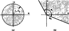
In the phase comparator operation takes place when the phase angle between the currents lies within specified limits (Figure 35.8(b)).
35.1.3.3 Multiple-input relays
By using more than two inputs, various forms of operating zone can be obtained, as required for distance feeder protection.
35.1.3.4 Types of relay
Attracted armature: This single-input relay comprises a small coil carrying the signal current: it attracts a magnetic armature with one or more pairs of contacts which control the secondary circuits, and is suitable for both d.c. and a.c. operation. The setting may be based on minimum pick-up or maximum drop-out current, with ranges usually selected by tappings to secure a constant value of operating m.m.f. Tapping changes the impedance and, therefore, the burden on associated c.t.s. The speed of operation is a function of the m.m.f., the length of armature travel and the inertia of the moving parts. The latter may be partly offset by counter-weighting. When the relay coil is intermittently energised, it may be uprated to increase the operating speed: a set of contacts may be provided which, when energised by the operation of the initiating relay contact, gives a holding effect. The current in the coils of tripping relays is then usually broken by an auxiliary switch on the circuit-breaker. Magnetic sticking of the armature in attracted-armature relays is prevented by stops of non-magnetic inserts on the working face.
Rotary: This is a rotary version of the foregoing. The armature is usually mounted on a vertical spindle, the rotating parts are light and well-balanced, and the relay is sensitive at a relatively low burden. Adjustment and accurate setting is by torsion head and helical spring control. In some types the armature carries a light silver contact, the coil operated contacts being energised when the silver contacts close. The relay can be made to operate with a few milliamperes, and both linear and rotary forms of the attracted-armature relay can be arranged for double-input working.
Induction: The time-dependent induction protective relay is probably the most widely used of all. It employs essentially the same construction as an integrating a.c. energy meter. For a single-input relay (Figure 35.9(a)) torque is produced by a phase difference between the flux of the main coil on the central limb of the upper magnet and that in the lower (secondary) magnet, an effect secured by impedance compensation in the secondary. The torque is proportional to the square of the exciting current and is unidirectional. The speed of the disc may be governed by a control spring and a permanent-magnet brake. Slots are cut in the disc to modify the operating time–current characteristic, and the shape of this curve at higher currents can be made almost flat if the magnetic circuit is arranged to saturate at two or three times the setting.

The driving disc usually has a vertical spindle, but one make of relay has a horizontal drum driven about its axis, the time—current characteristic being similar to that of the disc type.
The single-input relay is widely used for overcurrent protection. By feeding a separate signal to the secondary coil the relay becomes a double-input device with a torque proportional to I1I2 sin α, where α is the phase angle between the currents. In this form it can be given directional properties, and is also applicable to certain forms of distance protection.
Directional: Directional relays operate in a manner similar to that of an electrodynamic wattmeter or, more commonly, an induction energy meter. In the latter the torque on the disc is proportional to VI cos β, where β is the phase angle between the voltage and current inputs.
The maximum-torque angle is the angle by which the current applied to the relay must be displaced from the applied voltage to produce maximum torque. Although the relay may be inherently wattmetric, its characteristic can be varied by the addition of phase shifting components to give maximum torque at the required phase angle. Several different connections have been used, and examination of the suitability of each involves determining the limiting conditions of the voltage and current applied to each phase element of the relay for all fault conditions, taking into account the possible range of source and line impedances.
Beam: A balanced beam with two electromagnets can be used as a simple double-input device and has been widely applied to distance protection (Figure 35.9(b)). It can also serve as a directional relay.
35.1.4 Solid-state equipment
Thermionic valve equipment has been in use for a half-century in carrier current protective signalling. The advent of solid-state devices (transistors and thyristors) has made possible alternatives to electromagnetic relays.
The exploitation of integrated circuits and microprocessors has made a major impact on protection in recent years.
Solid-state equipment differs markedly from conventional electromagnetic equipment in several ways, particularly in the reduction in overall size.
The flexibility and characteristics enable schemes to be devised that are difficult to achieve conventionally, such as the distance relay with a quadrilateral characteristic (Figure 35.15(f)). For most applications the transistor has the advantage of high speed, high sensitivity and simple amplifying and switching properties. Where heavier currents are necessary, e.g. in a tripping circuit, the thyristor is required. Solid-state devices can, if desired, readily be associated with electromagnetic relays if the time delays (10–20ms) associated with the latter can be accepted; however, the lighter and faster (1–2 ms) reed relay is applicable in many cases.

Components are subject to damage by moisture, but encapsulation can obviate the trouble.
Static components have some resilience and very low mass; they can withstand mechanical shock and vibration, significantly reducing risk of damage during transport and erection.
All components, are sensitive to transient voltages, even of only a few microseconds duration. Such transients arise from switching, and can be injected into the protective equipment directly through current and voltage transformers, or by electric or magnetic field induction. Equipment must be impulse tested, e.g. by a 5 kV 1/50 μs impulse wave.
The burden imposed by static relay equipment on c.t.s is much less than that of comparable electromagnetic equipment. As the cost of instrument transformers is 20–40% of that of the complete protective scheme, smaller and improved types are being developed which may offset the higher cost of the static relay itself.
Even with conventional equipment, the use of 1 A secondary currents (instead of 5 A) is sometimes desirable, especially where long interconnecting leads are necessary. With static equipment even smaller currents can be used. The ultimate in this respect is a very small line mounted high-voltage current transformer feeding a laser system; the electromagnetic power (about 2 W) is converted to light power and transmitted to earth potential equipment by light-guides, the resulting power (a few microwatts) then being amplified and fed to static relay equipment.
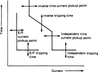
The range of solid-state relays now available covers many applications hitherto dealt with by electromechanical devices. The static equivalent generally offers greater flexibility in the design to meet given protection functions. Typical characteristics are shown in Figure 35.10 for static protection, which needs no auxiliary supply and provides a high reliability and accuracy.
35.1.5 Overcurrent protection
The most common overcurrent relay is the induction type, typical characteristics of which are given in Figure 35.11. The standard characteristic follows no simple law, but the very-inverse-time characteristic is (I − 1)t = k, and the extremely-inverse-time law is (I2 − 1)t = k.

The relay has two adjustable settings. The plug setting (current setting) comprises a tapped winding for the current coil, the tappings being brought out to a plug bridge on which, by insertion of the plug, current settings of 50, 75, 100, 125, 150, 175 and 200% of the full-load output of the current transformer (5 A) can be obtained; removal of the plug automatically short circuits the current transformer terminals. A time setting is achieved by varying the amount of travel of the contacts, giving time multipliers between 1.0 and 0.1. The times on Figure 35.11 are for a time setting of 1.0 and the currents are multiples of the plug setting current.
35.1.5.1 Discrimination
Graded time lags: On simple radial distribution systems, discrimination by graded time lags is effective, the lags of the relays being set successively longer for relays nearer to the supply source. The minimum time difference at all parts of the relay characteristic may be estimated as: error of relay 1 (near to fault), 0.1 s; circuit-breaker operating time, 0.1 s; over-shoot of relay 2 (nearer to supply), 0.04 s; error of relay 2, 0.1 s; total, 0.34 s. The greater low-current times of the extremely inverse time characteristic may be suitable for grading with fuses, and also are less likely to cause tripping on switching-in after a supply interruption, when there may be heavy overloads resulting from plant left connected.
Graded time lags and directional relays: If the overcurrent relays embody a directional feature (DOC), discrimination on more complicated networks can be obtained. Figure 35.12(a) shows a ring main: the arrows indicate the current direction for which the relays will operate, and the figures show typical time settings. The directional feature ensures that time grading can be obtained in each direction around the ring.

For the two parallel transformers in Figure 35.12(b) directional overcurrent relays are employed at the transformer ends on the LV side to detect phase faults on the line. Thus, a fault at F would be cleared by relays at C, while those at D would restrain. For a fault on the LV system both relays at C and D would restrain.
A more complicated network is shown in Figure 35.13. Suppose that the interconnector and feeder 6 are open and that there is a fault F on feeder 5. Fault current will then flow from the supply infeed direction into feeder 5 through 2. Now if feeder 2 is provided at each end with current operated relays having definite time delay, and if similar relays for feeder 5 are set lower than those for 2, then the former will operate first and clear the fault, after which the relays on 2 reset and leave the feeder still connected to the system. It will be apparent that a fault on feeder 2 will be cleared in a longer time than a fault on feeder 5.

Suppose now that feeder 6 is closed and that its relays are set the same as those of 5; then for fault F on 5 the relays on 5 and 6 both operate to trip both feeders. This unwanted result is avoided if the relays at the E end of 5 and 6 are set to a shorter time than those at the C end and provided with a directional feature; then for fault F the first operation will be the feeder 5 relays at E, and the second will be those at C, which are set in time to discriminate with the relays for feeder 2. Such a scheme is the simplest form of directional overcurrent protection, and at each point the relays provided may be (1) one overcurrent (o.c.) relay in each phase together with an earth fault (e.f.) relay, or (2) two o.c. relays and one e.f. relay, or (3) three o.c. relays only, where the system is solidly earthed. In the case of earthing through a resistor, the o.c. and e.f. relays would require different settings.
Consider the effect of closing the interconnector with a fault F on feeder 5. If the two radial systems are identical in length, feeder size and relay time settings, then, although fault current will divide between feeders 1 and 2, the first relays to operate will be those at E on feeder 5. However, when this occurs the fault is fed through 2, 6 and the interconnector; therefore the feeder 6 relays at E will operate first if their operating time plus that of the feeder 5 relays at E is less than the operating time of the feeder 5 relays at C. Furthermore, the interconnector cannot be proved with DOC relays satisfactorily for its own protection unless it is regarded as a ‘loose link’, in which case they would have to be set for rapid tripping to cut off the second infeed to a fault elsewhere on the system. If it is required that the interconnector should not trip, it must be provided with balanced protection and the o.c. relays set high for back-up.
A disadvantage of time graded systems is that the relays on feeders nearest to the supply point must have the longest operating times. As fault currents at such points are greatest, this is a drawback in the case of phase faults, though less so for single phase-earth faults, where fault current may be limited by earthing resistors.
Locking signals: To avoid the long time lags associated with overcurrent equipment, a scheme involving transmission of locking signals from the remote end of a line may be employed. Consider Figure 35.14, in which only the locking signal pilot and relay contact circuits are shown: if the o.c. relays at, say, the left-hand end detect a fault current, they will operate to close the trip-coil circuit of the circuit-breaker at that end; if, however, the directional relay at the right-hand end detects a fault current going out of the feeder (indicating a fault on another section), it initiates a signal on the pilot circuit which energises the lock-out relays and prevents tripping at both ends. A failure of the pilot circuit will cause the sending end to trip on a through fault but will not interfere with operation on an internal fault.
Either private pilot wires, telecommunication pilots or carrier current over the line itself may be used, the equipment for the latter being similar to that for carrier current phase comparison.
35.1.6 Fuses
The simplest overcurrent protection device is the fuse, which is used in vast numbers throughout the circuit operating voltage range 415 V to as high as 66 kV. The basic principle involves connecting a fuse directly in series with the protected equipment so that, when a given current is exceeded a metallic fuse ‘element(s)’ melts and thereby breaks the circuit. In this way, fuses both detect and directly isolate faulted equipment from the network.
The term ‘fuse’ is used in national and international standards to describe a complete assembly. In its simplest form, this consists of a piece of metal wire connected between two terminals on a suitable support; and at its most complex as a cartridge fuse-link mounted in a carrier and fuse base.
Modern cartridge fuse-links contain fusible elements mounted in rigid housings of insulating material. The housings are filled with suitable exothermal and arc-quenching powders, such as silica, and they are sealed by metal end-caps which carry the conducting tags or end connections. A typical fuse-link is shown in Figure 35.15. The metal parts, other than the fusible elements, are invariably of copper, brass, steel or composites and they must be capable of operating under the exacting thermal, mechanical and electrical conditions which may arise in service.
35.1.6.1 Fuse technology
A fuse must be able to carry normal load currents and even transient overloads (and the thermal cycling which accompanies them) for a service life of at least 20 years, without any change of state that might affect its electrical performance. This property of ‘non-deterioration’ requires that the fusible element be both thermally and chemically compatible with the ambient media. It must also respond thermally to overcurrents by melting and subsequently interrupting its circuits.
The melting of an element is followed by a period of arcing during which the electrical energy input can be very high, its magnitude and the duration of arcing being dependent on the protected circuit. Successful fault interruption implies that the arcing is wholly contained within the fuse-link and the level at which this can be achieved is termed the breaking or rupturing capacity of the fuse-link.
The operating time of a fuse-link varies inversely with the level of an overcurrent and discrimination is obtained in networks by choosing fuses with the necessary time/current characteristics and current ratings.
The time/current characteristic is determined by the design of the fuse itself, in particular but not exclusively, the fuse material and the physical geometry of the fuse link(s). In practice, the fuse/current characteristic is chosen to ensure adequate discrimination with other fuses and/or overcurrent relaying devices around the network. Figure 35.16 for example shows how, in general terms, a fuselink ‘f’ situated between protective devices ‘u’ on the source side and ‘d’ on the load side could be arranged to provide discriminative tripping on a radial feeder.

35.1.6.2 Fuse links with short operating times
All modern high-breaking-capacity fuse-links contain elements, usually with restrictions, of small cross-sectional areas connected between relatively massive end connections which act as heat sinks. To obtain rapid operation this principle is employed to a high degree. The extent to which the mass of the heat sink can be increased while reducing the length of the relatively thin element is determined by the requirement that the fuse should withstand the system voltage after the current has been interrupted i.e. it must not restrike. Considerable ingenuity has reconciled these two mutually incompatible requirements.
35.1.6.3 The M effect
The M effect, deriving from an exposition by Metcalf, refers to exploiting the thermal reactions of dissimilar metals in the control of time/current characteristics. The thermally most stable fuse element is a simple homogeneous metal. Such an element provides the highest degree of non-deterioration and reliability with adequate breaking capacity at higher overcurrents, but it may be insensitive to lower overcurrents. A lower melting temperature metal with high resistivity and, therefore, greater thermal mass, can be made to respond more sensitively to lower overcurrents but may be unreliable at higher currents.
The M effect is a means by which these extremes can be combined to produce a desired characteristic, but it needs to be used with care in design to avoid compromising non-deterioration properties. An element incorporating the M effect is shown in Figure 35.17(a).

35.1.6.4 Composite or dual-element fuses
Satisfactory operation throughout the overcurrent and short-circuit ranges is sometimes obtained in the same package by combining what are, in effect, two fuses connected in series in the same cartridge (Figure 35.17(b)). Typical of these is the so-called dual-element design common in the USA. The short-circuit zone is similar to the homogeneous element used in single-purpose HRC fuses. The overload zone may take the form of a massive slug of low-melting-point alloy, or some electromechanical device, e.g. two copper plates soldered together and stressed by a spring, so that when the solder melts the plate springs apart to interrupt the current.
35.1.7 Earth leakage protection
A current-to-earth on an HV system invariably indicates the presence of a fault: if large enough, it will operate the o.c. relays, but it is necessary to detect earth currents even if they are limited by resistance earthing of the neutral point. Separate earth leakage (e.l.) protective equipment is thus usually desirable. The arrangements shown in Figure 35.18 are available, usually with induction relays, or linear or rotary attracted-armature types for high sensitivity. (An overload conductor falling to earth of dry soil may produce no more than 5 A of earth fault current, but the associated potential field may be dangerous to human and animal life.)

Figure 35.18 Earth leakage protective schemes: (a) residual c.t.s; (b) neutral c.t.s; (c) frame leakage; (d) core balance; (e) overcurrent and earth leakage; (f) balanced (restricted earth leakage)
Schemes (a)–(e) in Figure 35.18 have no discrimination and operate for any fault beyond the equipment. If, however, the e.l. relays are given a time lag, any serious fault can be cleared discriminatively by o.c. or other protection. In (c) the transformer tank, switchgear frame or metallic bus-bar covering must be lightly insulated from earth: an insulation resistance of a few ohms is adequate, but it must never be short-circuited, e.g. by a length of conduit or a metal tool leant against it. Scheme (d) employs a ‘core balance’ c.t. in which the core flux is produced only by earth leakage currents. Scheme (a) is commonly extended to include two o.c. relays, as in (e).
Discrimination can be provided by balancing the e.l. currents at two points in the network. A common application is for the protection of the star-connected winding of a transformer (f) in which the e.l. relay will operate only for internal faults in the transformer.
A directional feature can be given to an e.l. relay, the second input being usually provided from open-delta voltage transformers.
35.1.8 Balanced (differential) protection
Balanced protection is based on the principle that the current entering a sound circuit is equal to the current leaving it, whereas, if faulted, the detectable current difference can be used to trip the appropriate circuit-breakers.
35.1.8.1 Circulating current schemes
The c.t.s in circulating current schemes operate with low-impedance secondary burdens, provided that the pilot wires are short, so that identical c.t. characteristics at the two ends are not difficult to achieve even under conditions of heavy fault; but a large d.c. fault current component may cause dissimilarity and spurious unbalance.
The relays must be located at the electrical mid-point of the pilot wires. This introduces no difficulty where the ends of the protected zone are not far apart, but is less suitable for feeders (although some are in fact so protected). Short pilot circuits obviate the need for summation transformers to reduce their number, and the arrangement of Figure 35.19 is typical. Circulating current protection is widely used for reactors, transformers, generators and bus-bars. In appropriate circumstances it has the advantages of simplicity, sensitivity and rapid response (e.g. 10–20 ms).

35.1.8.2 Opposed voltage schemes
As relays can readily be installed at each end of the protected zone, an opposed voltage scheme is suitable for feeder protection. Summation transformers or other means reduce pilot wires to one pair, but even so the pilot problems limit the practicable feeder length.
Per kilometre loop, the resistance of the typical pilot circuit with 7/0.075 mm conductors is 12.5Ω and the capacitance is about 0.1 μF. The c.t.s operate, even on internal fault, with a high impedance burden; on a through-fault they are virtually on open circuit, and unless precautions are taken, the voltage between pilot wires can reach 1 kV, making magnetic balance of the transformers difficult and also giving rise in the pilot wires to capacitance currents which are likely to cause maloperation. Of the many schemes devised to overcome these difficulties, that mentioned below is typical.
This scheme employs induction relays so arranged that only two pilot wires are required, their capacitance currents being used to give a restraining effect. The pilot wire voltage is limited to about 130 V. In Figure 35.20 consider a fault F between the R and Y phases: the currents in section (1) of the relay primary windings 11 and 11a induce e.m.f.s in 12 and 12a which, being now additive, circulate a current in the operating coils 13 and 13a and in the two pilot wires. Both upper and lower magnets are energised, and if the fault current exceeds the scale setting, the relays operate to trip their associated circuit-breakers. A fault between phases Y and B energises section (2) of windings 11 and 11a, while a fault between phases R and B energises both sections (1) and (2), the fault setting being one-half of that in the former cases.

In the event of an earth fault on line R, the resultant secondary current from the phase R c.t. flows through sections (1), (2) and (3) of windings 11 and 11a. A Y phase earth fault energises sections (2) and (3); and a B phase fault, only section (3).
Pilot wires: It is often desired, especially for feeder protection, to reduce the number of pilot wires to two. One method is the discriminating delta connection (Figure 35.21(a)) in which the c.t.s have different ratios (e.g. N, 3 N/4 and N/2). A more common method employs a summation transformer (b). If the primary turns of the summation transformer are in the ratios 1 between A and B, 1 between B and C, and n between C and N, then the relative sensitivities for various types of fault are in the following relative proportions as secondary outputs:

![]()
Stability ratio: High sensitivity is desirable to ensure operation of the relays on minor or incipient faults, while high stability is required to prevent operation on heavy through-faults. These requirements are in conflict and it is usual to restrain (‘bias’) the relays by an additional winding carrying a current proportional to the fault current, thus desensitising the response to heavy fault conditions. The ratio (maximum through-fault stable current)/(minimum fault operating current) can thus be made as great as 100.
Distance (impedance) protection: This type of protection, used chiefly for overhead lines, involves the measurement of the impedance of the circuit as ‘seen’ from the relay location; if this impedance falls below a specified value, a fault is present. The impedance observed is approximately proportional to the distance of the fault from the relay and discrimination is obtained by introducing time delays for the more distant faults. Two schemes are available, impedance time and steeped time, the latter being more widely used on lines above 33 kV, on account of the shorter operating times obtainable.
35.1.8.3 Impedance time scheme
Relays having a directional characteristic give an operating time proportional to the impedance presented, i.e. proportional to the distance of the fault from the relay. By locating such relays at each circuit-breaker on a succession of feeders the characteristics of Figure 35.22(a) are obtained. It can be seen that should a relay, e.g. that at B, fail to operate, it will be backed up by that at A after a time interval. With feeders of different lengths the slopes of the characteristics must be adjusted to give correct discrimination; thus, the relay at A must have characteristic X (dotted) rather than Y, as the latter would give incorrect back-up discrimination for a fault near the end of section CD. The relays cater for fault currents flowing from left to right; a similar set would be required to cater for fault currents from right to left.

35.1.8.4 Stepped time scheme
Three separate relays are required for each direction of fault current at every circuit-breaker location. The relays are of the induction or (more rarely) of the beam type. In Figure 35.22(b) relay 1 of the group at circuit-breaker A is set to give ‘instantaneous’ operation for faults occurring within the nearest 80% of feeder AB, i.e. over distance X1. Relay 2 operates, after a time lag, for faults occurring up to a point just beyond circuit-breaker B; it thus acts as a backup for relay A over the distance X1. Relay 3 operates with a still longer time lag for faults beyond the cut-off point of relay 2; it thus acts as a further back-up for relay A, and also for relay 2 over the last 20% of feeder AB.
35.1.8.5 Fault impedance
The impedance ‘seen’ by a relay depends upon the type of fault. Two sets of relays, differently connected to the system, are required (although a single set with a switching device is also practicable).
Earth fault: For a simple earth fault fed with current Ie and phase-to-neutral voltage Va of the faulted phase, the earth loop impedance presented to the relay is
where Z1 is the normal positive-sequence line impedance from the relay to the fault, Ze is the corresponding impedance of the earth path, and k = Ze/Z1.
Phase–phase fault: The relay is fed with the phase–phase voltage and with the difference (Ia − Ib) between the faulted phase currents, so that the impedance is
Earth current compensation: If, as is common, the system is earthed at more than one point, a proportion of the earth fault current will return by a path other than that at which the relays are located. The impedance seen is thus in error: it will be too low. This can be corrected in two ways.
Sound-phase compensation: A fraction p = Ze/(Z1 + Ze) of the sound-phase currents is added to the faulted-phase current, as shown in Figure 35.23(a). Typical values for a 132 kV line are Z1 = 0.44 Ω/km and Ze = 0.21 Ω/km, so that p = 0.34.

Residual compensation: A fraction q of the residual current Ir is added to the relay operating current, as in Figure 35.23(b). If q = Ze/Z1, the measured impedance is Z1, and the relays must be set for Z1 instead of for Ze to give correct operation. With the typical values above, q = 0.52.
Arc resistance: If the fault has an arc resistance, the relay will ‘see’ the fault as located too far away, and errors in discrimination may result. Typical values of fault resistance lie between 0.5 and 3 Ω, the higher values for lower currents.
Power swing: If a power swing occurs, i.e. phase swinging of the terminal voltages of the section of the system concerned, the impedance seen by a relay may fall to a low value even if there is no fault in or near its protected zone.
In Figure 35.24 the impedance seen by the relay at X and looking towards B is given by
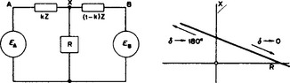
where A = (EA/EB) ∠ δ, with δ representing the phase angle between EA and EB, and Z the total impedance of the line. The expression gives approximately the linear impedance locus shown, part of which around δ = 90° may well fall within the operating zone of the relay and cause false tripping unless special precautions are taken.
35.1.8.6 Relay characteristics
Characteristics for various relay constructions are given in Figure 35.25, the relays operating if the impedances seen by them fall within the shaded area. The impedance for which a relay is required to operate is given by OZ1, OZ2 or OZ3 in Figure 35.25, so that this value should lie within the shaded area and any other impedance seen by the relay (due to load, arc resistance, power swings, etc.) should lie outside it. The quadrilateral characteristic (f) is desirable, but it can be obtained only by electronic means.

Typical arrangements for the three steps of a stepped-time scheme are also shown in Figure 35.25. At (g) the directional feature is given by the ‘mho’ relays used for the first two stages, while at (h) the mho relay for the third stage is used as a starting element and also prevents the reactance relays operating under load conditions.
Inaccurate operation can result if the relay voltages are low, owing to a high source/line impedance ratio, e.g. 30/1 or more. A polarising winding on the relay fed (1) through a memory circuit so that it retains pre-fault voltage or (2) from the sound phases through a phase shifting circuit, may be used. Method (2) is not effective for three-phase faults.
35.1.8.7 Accelerated distance protection
It can be seen from Figure 35.22(b) that faults near the remote end of the protected section AB will only be cleared after an appreciable time lag. Such a fault will, however, be cleared ‘instantaneously’ by the right-to-left equipment at B: and if this equipment is also made to transmit a signal to A over a pilot circuit (usually carrier over the line), it can initiate the immediate tripping of the circuit breaker at A, thus giving almost instantaneous protection over the whole line.
35.1.9 Miscellaneous equipment
Any fault other than a symmetrical three-phase fault develops negative sequence currents, so that a network responsive to n.p.s. but not to p.p.s. components will indicate the presence of a fault and can be made to operate a relay. Two such circuits are shown in Figure 35.26. The cross-connection of the current transformers in (a) eliminates the z.p.s. components: the latter are earth leakage currents and are detected in other ways. The n.p.s. schemes illustrated employ impedance elements of resistance R and inductive impedance Z = R 60°, but capacitive impedances Z = R ∠ −60° give the same results if the positions of R and Z are interchanged.

35.1.9.2 Neutral displacement
Displacement of the neutral point potential from its normal earth potential is indicative of a fault condition, and may be used to initiate tripping.
35.1.9.3 Buchholz relay
The Buchholz relay is used for the protection of large oil immersed transformers or shunt reactors with oil conservators, and is fitted in the pipe from the tank to the conservator. Any arcing fault causes the oil to decompose, generating gas which passes up the pipe to the conservator and is trapped in the relay. In the case of a large fault a bulk displacement of the oil takes place. In a two-float relay the upper float responds to the slow accumulation of gas due to the mild or incipient faults, while the lower float is deflected by the oil surge caused by a major fault. The floats control contacts–in the first case, to give an alarm; in the second case to isolate the unit.
Such relays also incorporate a petcock at the top for the removal of the gas; its subsequent analysis can show the origin and severity of the internal fault.
35.1.9.4 Tripping of circuit-breakers
Direct-operated trip coils: The circuit-breaker trip coil may be energised directly from the current in the main circuit for lower voltage circuit-breakers, or from a current transformer with the trip coil shunted by a fuse which blows on overcurrent to cause tripping. With c.t.s it is possible to use the residual current to operate the tripping at a much lower earth fault current than for overcurrents. The advent of solid-state relays enables much better fault discrimination to be achieved, and also obviates the need for external auxiliary supplies (usually d.c.) for tripping.
35.1.9.5 D.c. tripping and operating circuits
The d.c. circuits brought into operation by protective relays are of importance, as they are responsible for circuit-breaker actuation.
Single tripping: The tripping of one local circuit-breaker (‘unit tripping’) by the operation of relays is applicable to overcurrent or balanced protection of feeders having relays at each end. The essentials are shown in Figure 35.27(a); it includes a ‘healthy trip circuit’ indicating lamp with external resistance of such value that, if the lamp is short-circuited, the current is less than that required for tripping. The lamp also serves as a ‘circuit-breaker closed’ indicator, and proves the continuity of the trip circuit when the breaker is closed.
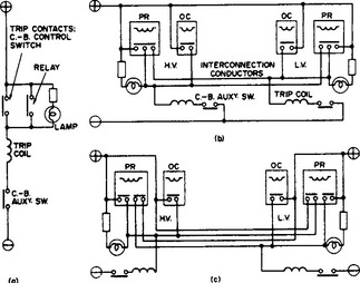
Intertripping: By this is meant the necessary tripping of circuit-breakers identified with the unit protected; for example, the tripping between HV and LV breakers on a transformer with (1) overall circulating current protection or (2) balanced earth leakage and overcurrent protection on each side, it being necessary to trip both breakers for a fault on either side. Intertripping may be local and relatively straightforward, or it may require to be performed on circuit-breakers at separated points in the network.
Local intertripping: When two circuit-breakers are involved, use can be made of a standard ‘three-point’ scheme, either with a three-point relay, or by the addition of an interposing relay which gives a positive tripping supply to two independent circuits. Figure 35.27(b) shows an arrangement with three-point relays and a common d.c. supply, and Figure 35.27(c) the modification for separate supplies. In both cases the overcurrent relays, whether for ‘back-up’ or phase fault protection, trip their respective breakers only. Buchholz protectors or high-temperature relays, where used, should be connected so as to intertrip. When transformers are feeding distribution networks, three overcurrent relays on the HV side only with intertrip to the LV breaker are sometimes used, i.e. with no overcurrent relays on the LV side. The disadvantage of this arrangement is apparent, for the tripping of the LV breaker depends solely on the intertripping wire or cable. Also, the overcurrent relays are inoperative with the transformer charged from the l.v. side only, and with balanced earth leakage on each winding there would be no phase fault protection, obviously a dangerous condition. It is considered better practice to install overcurrent relays on each breaker so that, in the event of damage or bad connection on the interconnecting pilots, the ‘back-up’ value of overcurrent relays will trip each breaker independently, as well as giving complete protection with either side energised.
Distance intertripping is applicable to feeder transformer protection with breakers situated in different stations, or to special schemes in some forms of bus-bar zone protection. Basically, feeder transformer protection is treated as a combination of (1) feeder protection, generally a balanced protection employing either circulating current or balanced voltage principles; (2) transformer protection in the form of restricted earth leakage or circulating current, both sections being independent on the a.c. side, but the arrangements necessitate the additional tripping of the breaker at the remote end of the feeder in the event of a fault on either side of the transformer.
Figure 35.28 shows an arrangement embodying a d.c. polarised relay which is energised over two pilot cables by the operation of the transformer protection relays. It is a ‘dead pilot’ system, as the pilots are connected to the d.c. supply through limiting resistors only when the protection operates–an obvious advantage. The scheme counters the induction of e.m.f.s in the pilots by earth fault currents in neighbouring main cables. Special relays, sensitive to d.c. but strongly biased against a.c, are also available for use in this arrangement.
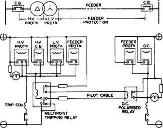
Another method, applicable to certain types of balanced voltage protection, operates by interrupting one pilot cable and applying d.c. or a.c. injection across the break.
Alarm systems: Modern protective relays are fitted with relay signals, but it is also necessary in attended stations to have audible and visual indication that a breaker has tripped. The methods are:
(1) Electrically operated alarm systems in which an alarm bell and lamp circuit are energised by a relay, manually reset or with self-holding contacts; in some makes a shunt or series coil closing suitable contacts is embodied in the protective relay. Separate contacts on a multipoint tripping relay, which are bridged when the relay trips, may be utilised.
(2) Mechanically operated free-handle type, in which an auxiliary switch is operated during the closing of the breaker, the alarm lamp and audible circuit being completed by an auxiliary switch on the circuit-breaker when it opens; this scheme gives the alarm not only when the breaker is tripped from protective relays, but also if the breaker slips or opens through mechanical vibration.
In all cases (with the exception of hand-reset alarm relays) cancellation of the alarm system is effected by turning the circuit-breaker controller to the open position.
D.c. supply: In large stations it is the practice to employ a trickle-charged ‘floating’ battery with charging from the local a.c. supply through a rectifier. Where no charging supplies are available, a replacement routine must be employed.
To reduce fire hazard, modern switchgear is sectionalised. The d.c. control circuits should be similarly sectionalised and fed from the main d.c. panel by separate cables.
35.1.10 Efficacy of protection scheme
The true measure of the efficacy of a protective unit may be expressed in terms of the number N of operations, of which n are incorrect, as (N–n)/N. The number N includes both through-faults and internal faults; n includes failure to trip on faults in the protected zone and false operation under through-fault conditions. Many factors influence this efficacy, such as imperfect design, application or commissioning, or failure of the equipment from damage and other causes. Protective equipment must therefore be carefully selected and meticulously maintained.
35.1.11 Digital protection
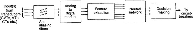
A digital relay is distinguished from other static relays, largely by virtue of the fact that transduced voltages and/or current signals are sampled at regular intervals and converted, prior to further processing, to digital words (or numbers) representing the instantaneous level of the signals sampled. Once converted, the sampled values are used as input values to the protection algorithm, which effectively comprises a set of equations that are continuously evaluated for each set of new data. The protection algorithms are stored in the memory associated with a digital microcomputer or microprocessor, which in turn performs the necessary calculations on each set of incoming data so as to determine the state of the item of plant or line protected.
The basic arrangement of a digital relay is shown in Figure 35.29. Each input signal is passed through an analogue low-pass filter which limits the frequency content of each signal to at least half the frequency at which data are produced.

In digital systems, any frequencies in the sampled signal above one-half of the sampling frequency appear in the digital area as lower frequency components or ‘aliases’ and prefiltering of the analogue data so as to band limit its frequency content is necessary to avoid such data corruption. An analogue-to-digital converter then performs the necessary conversion to produce a train of digital data to the microprocessor which performs the necessary protection algorithm calculations. In practice, sampling and associated calculations are performed at frequencies which range from typically 200 samples/s to 4000 samples/s; the sampling rate is to some extent dictated by the performance requirements of the protection and, in particular, the required operating times. Digital relays commonly quantise the incoming data into at least 12 bits which in turn enables the incoming signals to be represented by signals ranging from 0 to 211 (or ±2048) levels. The algorithmic calculations performed by the microprocessor will commonly involve 16-bit digital words (±32768), which in turn generally enables the necessary degree of accuracy to be obtained. Where the algorithms are such that a high computational burden is imposed, due for example to its complexity and/or the need for a high sampling rate, it is common to use a high performance digital signal processor in preference to a conventional microprocessor.
The microprocessor is equipped with random-access memory (RAM) and read-only memory (ROM) for data and program storage. Communication with the outside world is needed to program the relay settings into the device and display status information. This is achieved by a display and keypad. Alarm and tripping signals are produced via the outgoing relays and, in addition, digital outputs supporting fault location equipment, communications modems linking other digital equipment and relays at other locations, etc., are often integrated.
Digital relays offer a number of benefits over more conventional devices and, in recent years, a number of relays have been marketed. The primary impetus for the emergence of digital protection is a general increase in demands from utilities for faster fault clearance times, better discrimination and satisfactory detection of difficult or contingency fault conditions which are not easily met by more conventional relays. Complex operating characteristics are readily programmed into digital relays which have been designed to automatically monitor themselves by executing automatic check programs which identify potential problems by comparing the response of specific circuit elements with that expected for given reference test conditions. Digital relays are generally much more flexible than more conventional types since they often include multiple characteristics and options to select any one of these. They can readily accept inputs from the digital devices and are directly compatible with digital communication systems for performing data transmission, alarm handling and supervisory controls. It is highly likely that, in the future, increasing integration of digital protection with ‘electronic transducers’, e.g. fibre optic voltage and current sensing devices, will occur.
Digital relaying can be applied in unit or non-unit form to protect specific items of plant and/or power feeders. At the present time, the major applications have been in the area of e.h.v. transmission line protection of the distance, differential and directional comparison types.
35.1.11.1 Distance protection
A digital distance relay has an algorithm which is designed to calculate the impedance between the point of measurement and the point of fault. This is done for each set of samples of voltage and current measured. There are a number of specific methods of calculating the impedances, the most common of which involve implementing an algorithm that is designed to evaluate the resistance and reactance of the fault loop. By reference to Figure 35.30, which is a simplified single-line diagram of a transmission line fault loop, the relationship between the voltage and current measured at the relaying point and the fault loop resistance R and inductance L is given by

This equation applies to all samples processed. For example, consider two samples taken at times t1 and t2 (for which the voltage and current samples are denoted by v1, i1 and v2, i2, respectively). In this case the fault loop parameters can be obtained from an algorithm based on the equations
where i′ denotes a current signal rate of change (di/dt) and D = i1i′2−i′1i2
Estimates of the current differential terms together with the instantaneous values in the above two equations are obtained typically by utilising a succession of two or three sampled values and in this way, successive estimates of impedances measured are obtained. Such estimates are compared with the distance relay characteristic boundary, which is defined in accordance with the requirements of particular applications (see Figure 35.25 and Section 35.1.8.6). Tripping is initiated when a defined number of successive samples of the fault loop impedance consistently lie within the defined characteristic boundary and tripping times typically as low as 8 ms are readily attainable for most applications.
35.1.11.2 Differential protection
The circulating current differential principle is at present that which is most commonly applied in digital form (see Section 35.1.8.1). Figure 35.31 shows a functional single-line diagram of such a scheme applied to a plain feeder. In this arrangement, the currents at the two ends are sampled and transmitted to a digital differential relay located at only one end, though separate devices located at each end can be used. Each sample is converted to digital form and transmitted to a digital communications link which, in the case of Figure 35.31, comprises a light fibre optic link. Other digital communications channels, e.g. microwave links can equally be used. The current differential quantity, which is of the form given in Equation (35.4) is evaluated at each sample instant and compared typically with a bias quantity (Equation (35.5)). Internal faults are distinguished from healthy conditions by comparing the magnitude of successive estimates of the differential and bias quantities as determined by sampled digital values. In its simplest form, the algorithm checks that, for example, the differential quantity consistently exceeds the bias quantity for a number of successive samples before initiating circuit-breaker tripping. Where, as in Figure 35.31, the scheme is arranged on the ‘master and slave’ ends principle, a return fibre or digital communications channel can be used to transmit the signal from the measuring to the remote (slave) end.

35.1.11.3 Directional comparison protection
The basis of a directional comparison protection scheme is shown in Figure 35.32. In the particular arrangement shown, digital directional detectors measure from the voltage and current at each line end. Each directional measuring device is designed to determine the direction to the fault so that, for the faulted case shown, each measures the fault as being in the forward direction. The fault direction indicated is signalled to the equipment at the other end to produce a tripping signal. Conversely, any fault external to the line causes only one directional detector to indicate a fault in the forward direction and tripping is thereby inhibited. There are a number of alternative ways of utilising the directional indications issued, but the basic principle is the same as that outlined above. It is worth noting that only a single binary signal is required in transmitting the directional signal determined by the detectors, thus avoiding the necessity for multi-valued data communication channels.
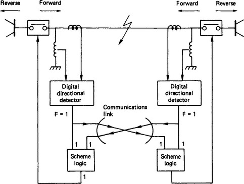
It is common for digital directional comparison devices to measure from the fault superimposed voltages and currents. The superimposed measurands are in effect the difference between the actual value measured and the projection of the normal steady-state voltage (or current) existing at the point of measurement immediately before a fault. The superimposed voltages and currents can thus be considered as existing in their own right in an otherwise de-energised system, i.e. they propagate within a model of the system in which each voltage is hypothetically set at zero. For example, Figure 35.33 shows the form of the resulting superimposed circuit for a transmission line subjected to a fault somewhere behind (or in the reverse direction with respect to) the directional measuring point at end S. Figure 35.33 is a simplified superimposed model of a multiphase line in which the three-phase voltages and currents are combined into single voltage and current measurements. The means of achieving this network reduction is similar to that used to derive single measurements in distance protection (see Section 35.1.8.5) and further detailed information is given in the Bibliography at the end of this chapter.

The directional detectors derive superimposed measurements which are usually obtained by taking the difference between any sample on the incoming waveform and that derived from an integer number of power frequency samples previously; this differencing is equivalent to projecting the prefault steady-state variations forward in time and makes the resulting measurements consistent with a system superimposed model of the type previously discussed.
With reference to Figure 35.33, the superimposed voltage and current measured at say end S (vT, iT) are related for all time up to twice the wave transit time (2τ) from S to R by vT = zoiT, where zo is the line surge or characteristic impedance. Successive sampled values of vT and iT are used to form the directional signals
The directional signals given in the above equations are compared to determine the direction to the fault. For the reverse fault shown in Figure 35.33, the signal tends to zero whereas the signal s1 attains a relatively large value which leads to twice the superimposed voltage measured at end s2. Conversely, for a forward fault, the superimposed voltage and current are of opposite sign and in this case a reverse fault direction is indicated by signal s1 exceeding signal s2. Directional integrity is obtained by checking the relative size of signals over a number of post-fault samples, and the direction to a fault can be obtained in typically 2–4 ms when using a sampling rate of 3000 samples/s. The use of superimposed quantities brings a high degree of immunity to power swing and heavy circuit loading effects on account of their value being close to zero under normal steady-state conditions.
35.1.12 Artificial intelligence for protection
Conventional relays, including digital devices, rely heavily upon deterministic signal models and heuristic approaches for decision making and only a small amount of the total information available within the voltage and/or current signals used in the measuring process is utilised. Similar considerations apply in respect of relay settings and in recent years various artificial intelligence (AI) techniques have been investigated for use in the protection field. A vast amount of work has been done on the design of ‘Intelligent relays’. In particular three mathematical AI tools lead themselves well to the protection field, i.e. expert systems, fuzzy logic and artificial neural networks.
35.1.12.1 Expert systems
The prime function of protective relays is the timely and discriminative clearance of system faults. In practice, a particular relay has to be set so as to ensure that its response is such that its operation is co-ordinated with that of other relays on a system. In this respect, the co-ordination of distance relays on an interconnected network is a longstanding problem. Consider for example the simple configuration of Figure 35.34, where relay Rx is ideally required to act discriminatively to clear faults on line PL as well as act in a backup mode for faults on lines SL and YL.
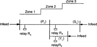
The basis of setting distance relays is explained in Section 35.1.8.4 but it will be evident from Figure 35.22(b) that simple time grading of relay Rx in zones 1, 2 and 3 as indicated could for example result in that relay seriously underreaching in zones 2 and/or 3, where the infeed via line YL is significant enough to cause an ‘apparent’ increase in the impedance measured from relay Rx to a fault on line SL. A relay or protection which operates to clear faults over a distance which is less than the desired or set value is said to underreach. The effect of such underreaching could for example be to increase the time of operation of relay Rx in circumstances where fast clearance of faults on line SL is required under conditions where a circuit breaker on line SL fails. The derivation of suitable settings for distance relays is a knowledge intensive problem that requires the experience of senior relay engineers. It is a time consuming task that is often complicated by the presence of a multiplicity of relays having different operating characteristics. Expert system based methods are particularly suited to the problem of deriving suitable settings. In essence expert systems are computer programs that contain sets of rules established using the experience of experts, which are applied to the problem in hand. The programs are thus built from explicit information derived from human experts using symbolic representation, inference and heuristic search techniques.
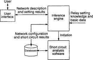
The basic elements of an expert system for deriving relay settings is shown in Figure 35.35. The inference engine commonly uses the AI software language Prolog which interacts with the user interface to accept network description from the user and supply the relay setting results.
35.1.12.2 Fuzzy logic
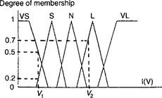
The majority of conventional protection techniques involve defining circuit breaker states by identifying the patterns of the measured voltages and/or currents. In practice however, there exists a significant degree of uncertainty and vagueness due to the complex relationships between the system response to disturbances and the resulting measurands. Examples of the factors contributing to such vaguenesses are signal transducer noise caused by electromagnetic interference and changes in load, generation or the network topology. Fuzzy logic has and is still being extensively investigated as a means of developing novel protection for power systems. It is essentially a method of readily representing human expert knowledge on a digital processor in particular where mathematical or rule-based expert systems experience difficulty. Figure 35.36 shows the basic structure of a relay utilising fuzzy logic. The sensor data is converted to fuzzy data using a fuzzification process in which each variable is assigned a degree of membership of a particular fuzzy class. For example, Figure 35.37 shows membership features for a particular voltage or current measured; here the process of classification involves defining the measurand as being very small (VS), small (S), normal (N), large (L), or very large (VL). Thus for example the vector showing the degree of membership for a voltage of magnitude V1 would be [VL, L, N, S, VS] = [0, 0, 0, 0.2, 0.5] whereas for a voltage V2, the corresponding vector would be [0, 0.7, 0, 0, 0]. A matrix of degree of membership is formed and the inference engine applies in effect a number of rules each of which generates a fuzzy parameter which is defuzzified to provide a crisp control signal which is channelled to the circuit breaker(s). There are a number of algorithms that are applied in the defuzzification process, the most common of which is the so called ‘maximum algorithm’ in which the element in the matrix with the largest membership value is chosen to define the required breaker control action.

35.1.12.3 Artificial neural networks
Artificial neural networks (ANNs) resemble the structure of the human brain but many experts are of the opinion that the resemblance is very superficial. In engineering terms, what is important is that the ANNs can be ‘trained to perform’ a required action. They are being developed for use in the protection field by using massive training sets of data for which the required response is known. Figure 35.38 shows the topology of a simple ANN. The inputs are normally derived from measured voltages and/or currents derived from the power system via voltage and current transducers. Various features are extracted from the measured signals e.g. the magnitude of a harmonic in a voltage signal may form one input signal. It can be seen that the ANN is built up of a number of nodes (or artificial neurons) each of which summates weighted input signals and further weights the sum before transmitting the output to other neurons. In practice an ANN may have a number of hidden layers the number of which depends on factors relating to the nature and extent of the protection problem; the single hidden layer network is however by far the most common and has been found to provide a satisfactory performance in most protection applications. Each artificial neuron employs a non-linear weighting function of which a number are employed. In essence however all weighting functions behave so as to produce an output level which suddenly switches from a low signal level to a high level when the summated input reaches a critical level.

Figure 35.39 shows the basic structure of a relay employing an ANN. As mentioned previously, the ANN needs to be trained. This is done using a training algorithm of which the ‘backpropagation’ algorithm is often used. In essence, the ANN is subjected to an input array derived via system simulation studies or actual recorded system data, for which the desired output is known. For example, the input may be derived from a faulted transmission line for which a tripping signal is required or conversely an input array associated with a healthy situation where the output should be zero. Training is performed iteratively by adjusting the weight of the input to each artificial neuron so as to obtain the desired output(s). In practice training has to be achieved using a training set which is large enough to ensure final convergence of the network weighing coefficients. Very significant progress has been made in the application of ANNs to protection and associated control functions such as single-pole autoreclosure. A number of commercial developments are underway and there is little doubt that ANN based protection and control will ultimately be applied. In this respect, it is likely that the first applications will be aimed at providing improved performance of protection in difficult applications and where it is necessary to cover contingency fault and systems conditions where more conventional protection, including digital measuring devices, often provide less than optimal response.
35.1.12.4 Hybrid artificial intelligence networks
Recent research indicates that AI based protection techniques may be significantly enhanced by the integration of expert systems, fuzzy logic and artificial neural network techniques. Fuzzy neural networks are actively being researched as a means of further enhancing next generation protection performance. Further integration of expert system techniques is also likely to provide a very important way forward in future generations of ‘intelligent protection’, though much more on-going work is required in this area.
35.2 Application of protective systems
There are usually several ways of protecting any given equipment, and the more usual zones of protection are shown in Figure 35.40. One relay can often be used for several functions; for example, a triple-pole overcurrent relay can be used for both overcurrent and earth fault protection, and the following combinations are commonly found in practice: (1) inverse time overcurrent and earth fault; (2) inverse time with instantaneous high-setting overcurrent, with or without inverse time earth fault; and (3) thermal overcurrent, with instantaneous overcurrent and earth fault.
Figure 35.40 Zones of protection: A, bus-bars; B, generator; C, generator-transformer; D, power transformer; E, auto-transformer; F, unit transformer; G, earthing transformer; H, transmission line of feeder; I, transformer; J, reactor; K, induction motor; L, synchronous motor; M, rectifier
The power system neutral is considered to be earthed when the neutral point is connected to earth directly or through a resistor. Earth fault protection is applicable in all such cases. The neutral point is considered to be insulated when the neutral point is not connected to earth, or is earthed through a continuously rated arc suppression coil or through a voltage transformer.
Arc suppression coils are a form of protection applicable where the majority of the earth faults are expected to be of a transient nature only. They can be continuously or short-time rated (normally 30 s), with one phase of the system faulted to earth. The continuously rated coils can be provided with an alarm to indicate the presence of a persistent fault, and in some cases directional earth fault relays are used to indicate the location of an earth fault. The short-rated coil is short-circuited, either directly or through a resistor after a short time, so that persistent earth faults can be cleared by normal discriminative earth fault protection.
35.2.1 Plant
The core of an electrical power system is the generator, requiring a prime mover to develop mechanical power from steam, gas, water or diesel engines. The range of size extends from a few hundred kilovolt-amperes up to turbine driven sets exceeding 600 MV-A in rating. Small sets may be directly connected to the distribution system, while the larger units are associated with an individual step-up transformer through which the set is coupled to the transmission system.
A modern generating unit is a complex system consisting of the generator stator, the rotor with its field winding and exciters, the turbine and associated condenser, the boiler with auxiliary fans and pumps, and possibly an associated or unit transformer. Faults of many kinds can occur in such a system, for which diverse protective means are needed. The amount of protection applied will be governed by economic considerations. In general, the following faults need to be considered:
The neutral point of a generator is normally earthed, with some impedance inserted in the earthing lead to limit the magnitude of earth fault current to values from a few amperes to about rated full load current. Phase–phase faults clear of earth are unusual, as are interturn faults; and they usually involve earth in a short time. Circulating current biased differential protection is the most satisfactory way of protecting a generator stator or a generator–transformer unit.
Generators on a large system under continuous supervision are not usually subject to prolonged accidental overloading and are often protected only by built-in temperature measuring devices on both stator and rotor. For the smaller machines inverse definite minimum time (i.d.m.t.) overcurrent relays are used (often forming a back-up feature) and may be voltage restrained to give better discrimination.
Power frequency overvoltages are usually dealt with by instantaneous relays with fairly high settings, and transient overvoltages by surge diverters and capacitors connected to the generator terminals if the incoming surges are not sufficiently reduced by transformer interconnections.
Any unbalanced load produces negative sequence components, the resulting reaction field producing double-frequency currents in the field system and rotor body, which can result in serious overheating. For turbo sets the negative sequence continuous rating is only 10–15% of the continuous mean rating value for positive sequence. The unbalance is detected by relays in a negative sequence network, providing first an alarm and finally tripping the generator load.
Rotor faults due to earthing of the winding, or partial short-circuited turns, can be detected by methods involving a potentiometer across the winding, or a.c. or d.c. injection. Failure of the field system results in a generator losing synchronism, running above synchronous speed and operating as an induction generator with the main flux produced by reactive stator current drawn from the system. In general, a 60 MW machine with conventional cooling will not be overheated by asynchronous operation at full load for 5 min; but a hydrogen cooled 500 MW set should not be run like this for more than 20 s. A generator may also lose synchronism because of a severe system fault, or operation at a high load with leading power factor and, hence, a relatively weak field. This subjects the generator and prime mover to violent oscillations of torque, but synchronism can be regained if the load is reduced in a few seconds; otherwise it is necessary to isolate the machine. Alternatively, the excitation may be removed so that the generator runs asynchronously, thereby removing the violent power oscillations. Re-closing the excitation at a low value will then cause the machine to resynchronise smoothly. The range of possible positions of saving curves makes detection by simple relays relatively difficult, but by the use of two impedance relays, pole slipping can be detected and corrected by varying the excitation.
Various faults may occur on the mechanical side of the set, such as failure of the prime mover, overspeed, boiler failure, loss of vacuum, lubricating oil failure, rotor distortion, etc. These can all be protected, the inclusion being a matter of economics.
Where generator-transformers are used, the differential protection will always need to be biased, using either harmonic bias or special attention to settings. Earth fault protection will cover the generator and the transformer primary winding; in addition, the transformer h.v. winding will usually be provided with restricted earth fault protection and Buchholz protection (see Figure 35.41).

The field of a faulty generator should be suppressed as quickly as possible. For machines above about 5 MV-A this is usually done by connecting a field discharge resistor of about five times the rotor field-winding resistance in parallel with the generator field when the field circuit-breaker opens. This reduces the field time constant, but it may still be more than 1 s.
35.2.1.2 Transformers
The power transformer is one of the most important links in a transmission system, and as it has the greatest range of characteristics, complete protection is difficult. These conditions must be reviewed before detailed application of protection is settled. The ratings of units used in transmission and distribution schemes range from a few kilovolt-amperes to several hundred megavolt-amperes. The simplest protection, such as fuses, can be justified only for the small transformers; those of the highest ratings have the best protection that can be afforded.
A fault in a transformer winding is controlled in magnitude not only by the source and neutral earthing impedance, but also by the leakage reactance of the transformer, and the fact that the fault voltage may differ from the system voltage according to the position of the fault in the winding. Star-connected windings may be earthed either solidly or through an impedance, presenting few protection problems; but delta-connected windings require close consideration, as the individual phase currents may be relatively low. Faults between phases within a transformer are comparatively rare, and interturn faults in low-voltage transformers are unlikely unless caused by mechanical force on the windings due to external short circuits. Where a high-voltage transformer is connected to an overhead transmission line, a steep-fronted voltage surge due to lightning may be concentrated on the end turns of the winding, resulting in 70–80% of such transformer failures unless some form of voltage grading is employed. The bolts that clamp the core together are insulated to prevent eddy currents. Should this insulation fail, then severe local heating may damage the winding. As the oil is usually broken down, the gas produced can be used to operate a Buchholz relay. Tank faults are rare, but oil sludging can block cooling ducts and pipes, leading to overheating.
One of the major problems in the protection of large transformers is the phenomenon of magnetising current inrush when switching on. This is not a fault condition and the protection relays must not trip, although the inrush current appears superficially as an internal fault and may have a long time constant. To avoid long time delays and, hence, damage to important transformers, it is essential to clear all faults rapidly. Use is made of the fact that magnetising inrush currents contain a unidirectional component plus second, third and higher harmonics. The second harmonic is the most useful as a stabilising bias against inrush effects, and by combining this (extracted through a filter) with the differential current through a static device, a setting of 15% can be obtained, with an operating time of 45 ms for all fault currents of two or more times rated current. The relay will restrain when the second harmonic component exceeds 20% of the current.
Most of the usual transformer arrangements such as star/delta, auto-, earthing, etc., can be protected by differential relays, sometimes with restricted earth fault relays.
Sometimes transformers are connected directly to transmission lines without circuit-breakers. In such cases the transformer and feeder are both protected by differential protection plus intertripping of the remote circuit-breaker. An alternative to intertripping is to detect earth faults on a feeder connected to a non-earthed transformer winding by measuring the residual voltage on the feeder, using either voltage transformers or capacitors to detect the neutral displacement.
35.2.1.3 Reactors
The most common are the series and tie-bar reactors, for limiting overcurrents. On earthed systems with air insulated reactors the protection usually consists of differential relays or time-delayed overcurrent with time-delayed earth fault relays. For insulated-neutral systems the earth fault relays are unnecessary. Shunt reactors for compensating line capacitance are usually oil immersed and protected by time-delayed overcurrent relays, with instantaneous restricted earth fault relays where the system neutrals are earthed. Buchholz relays are often used on oil immersed reactors.
35.2.2 Feeders
Many schemes are available: therefore, only general guidance can be given. Scope still exists for adapting schemes to individual requirements. Fuses and/or overcurrent protection with graded time lags are commonly used for 11 kV and 33 kV distribution systems with balanced opposed-voltage schemes for the more important 33 kV lines.
The protection can be by either electromagnetic or static relays, both of which may be switched by fault detectors, and for earthed systems can incorporate earth fault relays.
The length of feeder frequently results in additional circuits being necessary between the relays at each end. Pilot wires are often used for this purpose, but for distances above about 20 km the pilot wires may behave as a transmission circuit, and may need shunt reactors to compensate for the circuit capacitance. Pilot wires are also liable to electrical interference, manual disturbance and limits as to over-voltage and current, so that many schemes are provided with continuous supervision to warn that the overall protection is unsound and relay adjustment may be necessary. By using the line itself as a link and injecting high-frequency signals (70–700 kHz), the necessary end-to-end protective coupling can be achieved. Information is impressed on the signal by a modulation process. Attenuation of the signal carrier makes pilots unsuitable for transmitting the amplitude of a measured quantity; however, the phase can be transmitted satisfactorily. Frequency modulation can convey all the characteristics of the modulating quantity but involves frequency-amplitude conversion. The best use of carrier involves simple on/off switching: this method of modulation has been extensively used in conjunction with polyphase directional relays by transmitting a locking signal over the line for through-faults.
With extensive power systems and interconnection to ensure continuity of supply and good voltage regulation, the problems of combining fast fault clearance with protective gear co-ordination have become increasingly important. To meet these requirements high-speed protective systems suitable for use with automatic reclosure of the circuit-breakers are under continuous development and are already very widely used. The distance scheme of protection is comparatively simple to apply and offers high speed, primary and back-up facilities, and needs no pilot wires; but by combining it with a signal channel (such as carrier) it is particularly suitable for use with high-speed auto-reclosing for the protection of important transmission lines.
Since the impedance of a transmission line is proportional to its length, it is appropriate to use a relay capable of measuring the impedance of a line up to a given point. The basic principle of measurement (Section 35.1.8) involves the comparison of the fault current seen by the relay with the voltage of the relaying point, whence it is possible to measure the impedance of the line up to the fault. The plain impedance relay takes no account of the phase angle between the current and voltage applied to it, and is therefore non-directional. It has three important disadvantages:
(1) it is inherently non-directional and therefore needs a directional element to give it discrimination;
(2) it is affected by arc resistance; and
(3) it is highly sensitive to power swings, because of the large area covered by the impedance circle.
The admittance relay, by addition of a polarising signal, combines the characteristics of the impedance and directional relays. It is satisfactory on long lines carried on steel towers with overhead earth wires, where the effect of arc resistance can be neglected, but for lines on wooden poles without earth wires the earth fault resistance reduces the effective zone to such an extent that most faults take longer to detect. This problem can usually be overcome by using either reactance or fully cross-polarised admittance relays for the detection of earth faults. In theory, any increase in the resistive component of the fault impedance has no effect upon a reactance relay: however, in practice, when the fault resistance approaches that of the load, then the relay characteristics are modified by the load and its power factor and it may cover either more or less of the line. This can be overcome by the use of a fully cross-polarised circuit which needs two input signals for a ±90° comparison angle.
A distance protection scheme comprises starting, distance measuring, auxiliary, zone timer and tripping relays. To cater for the economic and technical requirements of a particular power system, schemes are available using either a plain distance measurement with several steps of protection, or a combination of distance measurement and a high-speed signalling channel or power-line carrier to form a unit system of protection over the whole of the protected line and to provide its own back-up protection to the adjacent lines. Full-distance, or switched-distance, schemes are applied according to the system voltage and the importance of the lines to be protected. The main difference between the two arrangements is that the full-distance scheme uses six measuring units (three for phase and three for earth faults), whereas the switched-distance scheme uses only one measuring unit for all types of fault, this being switched to the correct fault loop impedance by means of a suitable set of starting units of the overcurrent or underimpedance type.
One of the main disadvantages of conventional time stepped distance protection is that the instantaneous zone of protection at each end of the protected line cannot be set to cover the whole of the feeder length. It usually covers about 80%, leaving two end zones in which faults are cleared instantaneously at one end of a feeder but in much longer time at the other end. In some applications this cannot be tolerated; either the delay in fault clearance may cause the system to become unstable, or, where high-speed auto-reclosing is used, the non-simultaneous opening of the circuit-breakers interferes with the auto-reclosing cycle. These objections can be overcome by interconnecting the distance protections at each end by a signalling channel to transmit information about the system conditions at one end to the other end of the protected line. It can also initiate, or prevent, tripping of the remote circuit-breaker. The former arrangement is a ‘transformer trip scheme’, while the other is a ‘blocking scheme’.
If two circuits are supported on the same tower or are otherwise in close proximity over the whole of their length, there is mutual coupling between them. The positive and negative sequence coupling is small and usually neglected. The zero sequence coupling cannot be ignored. Types of protection that use current only (e.g. power-line carrier phase comparison and pilot-wire differential systems) are not affected, whereas types using current and voltage, especially distance protection, are influenced by the phenomenon and its effect requires special consideration.
The protective schemes described previously for the protection of two-ended feeders can also be used for multi-ended feeders with load or generation at any terminal. However, the application of these schemes to multi-ended feeders is much more complex and requires special attention.
As transient faults, such as an insulator flashover, make up 80–90% of all faults on HV and e.h.v. systems, and are cleared by the immediate tripping of one or more circuit-breakers, they do not recur when the line is re-energised. Such lines are frequently provided with auto-reclosing schemes, and result in a substantial improvement in continuity of supply and system stability. The choices of dead time, of reclose time, and of whether to use a single- or a multi-shot scheme, are of fundamental importance. With a three-phase scheme the tripping of all three phases on the occurrence of a fault means that no interchange of synchronising power can take place during the dead time. If only the faulty phase is tripping during earth fault conditions (which account for the majority of faults on overhead lines), synchronising power can still be interchanged through the healthy phases, but this entails the provision of circuit-breakers provided with tripping and closing mechanisms on each phase, and the reclosing circuitry is more complicated. In the event of a multi-phase fault, all three phases are tripped and locked out. It is important to ensure simultaneous tripping of the circuit-breakers at all ends of the faulty section, and distance protection imposes some difficulties in this respect, so that a signalling channel is often used between ends. On highly interconnected transmission systems where the loss of a single line is unlikely to cause two sections of the systems to drift apart and lose synchronism, three-phase auto-reclosing can be delayed for 5–60 s with an increase in successful reclosures.
35.2.2.1 Bus-bars
Bus-bars have often been left without specific protection for one or more of the following reasons.
(1) The bus-bars and switchgear have a high degree of reliability and are often regarded as intrinsically safe.
(2) It was feared that accidental operation of bus-bar protection might cause widespread dislocation which, if not quickly cleared, would cause more loss of supply than the very infrequent bus-bar faults.
(3) It was expected that system protection, or back-up protection, would provide sufficient bus-bar protection if needed.
The reasons are applicable only to small indoor metal enclosed stations: with outdoor switchgear the case is less clear, for although the likelihood of a fault is higher, the risk of damage is much less. In general, bus-bar protection is required when the system protection does not cover the bus-bars, or when, to maintain system stability, high-speed fault clearance is necessary.
To maintain the high order of stability needed for bus-bar protection, it is now an almost invariable practice to make tripping dependent on two independent measurements of fault quantities. Methods include: (a) two similar differential systems; (b) a single differential system (Figure 35.42), checked by a frame earth system (Figure 35.43); (c) earth fault relays energised by c.t.s in the neutral earth connection; (d) overcurrent relays; and (e) a frame earth system checked by earth fault relays. Separate current transformers are normally used with separate tripping relays series-connected in pairs to provide a single tripping output, so that independence is maintained throughout. The essential principle is that no single occurrence of a secondary nature shall be capable of causing an unnecessary trip of a bus-bar circuit-breaker.


35.2.3 Motors and rectifiers
Protection is required against (a) imposed external conditions, and (b) internal faults.
Category (a) includes unbalanced supply voltages, under-voltage, single-phasing, and reverse-phase-sequence starting; (b) includes bearing failures, internal earth faults and overloads.
Motors up to about 400 kW usually have ball or roller bearings which may fail very quickly: the only remedy is to disconnect the motor as rapidly as possible to avoid the overcurrent damaging the windings. Larger machines usually have sleeve bearings, incipient failure of which may be detected by a temperature device embedded in the bearing. As the current increase may be only 10–20%, it cannot be detected by the overload relays.
The majority of winding failures are caused by overload, leading to deterioration of the insulation followed by electrical fault in the winding.
The wide diversity of motor designs makes it impossible to cover all types and ratings with a simple characteristic curve. Motors with fluctuating loads where shutdown would affect the whole process might be left running by giving the overload relay a higher current setting. Motors on a steady load can be tripped more quickly, as overload will probably be due to a mechanical fault.
A temperature compensated static relay can follow changes of the working temperature of the motor more accurately, so that it will not be shut down on overload unless it is overheated. By including a number of alternative operating time-current characteristics it is possible to cover a wide range of motor designs and applications. Protection of motors operating on unbalanced voltages is provided by separating the positive and negative sequence components of the line currents by means of a sequence filter, arranged to allow for the greater relative heating effect of negative sequence current components.
35.2.3.2 Rectifiers
The majority of rectifier duties are now performed by semiconductors: these have special demands for protection. Faults can be classified as: (a) cell overload and failure; (b) operational faults such as backfires; (c) d.c. faults on the bus-bars and cables; and (d) a.c. faults on the supply transformer and cables.
Because of their low thermal mass and consequent low fault-current withstand, the series- or parallel-connected cells need to be individually protected, usually by fuses shunted by a small indicating fuse which, on blowing, operates a microswitch to trip the supply or give an alarm.
Semiconductor cells are susceptible to overvoltage failures caused by switching or lightning surges, arc voltages on fuse clearance, chopping of load current, etc. Protection usually takes the form of surge diverters or resistor/capacitor networks connected to earth (or between phases) and across the d.c. output. Rectifier transformers are often provided with earthed screens between the windings to limit the surge transfer.
35.3 Testing and commissioning
The testing of protective schemes has always been a problem, because protective gear is concerned only with fault conditions and cannot readily be tested under normal system operating conditions. The problem has been aggravated in recent years by the complexity of protective schemes and relays.
Protective gear testing may be divided into three stages: (1) factory tests, (2) commissioning tests, and (3) periodic maintenance tests.
The first two stages prove the performance of the protective equipment during its development and manufacture, and in its operational environment. The last stage, properly planned, ensures that this performance is maintained throughout its life.
The relay manufacturer must provide adequate testing of protective gear before it is accepted and commissioned. The tests performed are (a) tests in which the operating parameters of the relays, etc., are simulated; (b) conditions such as temperature range, vibration, mechanical shock, electrical impulse withstand, etc., which might affect the operation in service. In some cases tests of both groups are conducted simultaneously to check performance.
With the advent of static relays the use of semiconductors and other electronic components has posed new problems to the manufacturer, because the production of such devices is not within his control. Quality control testing procedures have been established with the object of identifying the device that may fail early in its life, the usual method being to determine which critical parameters will show a substantial change when subjected to accelerated life testing and to examine these.
35.3.1 Commissioning tests
The object of the commissioning tests is to ensure that the connections are correct, that the performance of current transformers and relays agrees with the expected results, and that no components have been damaged by transport or installation. This performance test includes correct current transformer ratio, correct calibration of relays and tests proving that the tripping, intertripping and indication of the scheme are in order.
Although the details of every protective scheme vary, the main points to be checked on every scheme are: (a) stability of the system under all conditions of ‘through’ current; (b) that the sensitivity of all relays with reference to the primary current is correct.
Prior to making these final checks on site a very careful preliminary check on the protective gear scheme should be made. Such tests would include:
(1) examination of all small wiring connections, and insulation resistance tests on all circuits;
(2) identification of all pilot cables–insulation resistance tests and loop resistance tests on balanced pilot-wire schemes;
(3) polarity and ratio check (if possible) on all current transformers;
(4) tests on d.c. tripping, intertripping and operation of all breakers connected with the unit, including alarm circuits and relay signals;
(5) checking of calibration of all relays by secondary injection; and
(6) miscellaneous tests depending on special details of a particular scheme.
35.3.1.1 Saturation curve
Considerable use on site may be made of a c.t. saturation curve using a LV local supply; it compares closely with results obtained by primary current. An LV a.c. supply is fed to the secondary winding through a control rheostat, and a curve of voltage–current for the secondary is plotted. The equivalent primary current is inferred from the turns ratio. The test is useful for comparing the performance of c.t.s required to have matched characteristics.
Such preliminary tests ensure that components are correct. The commissioning process thereafter must depend upon site facilities. The following notes give a general outline.
35.3.2 Primary current tests
A generator is isolated with the unit under test and by means of primary short circuits and earth faults stability figures, on balanced systems, under full load conditions and operation tests with internal faults may be carried out. It is important that the makers of the generator be consulted before it is used for steady unbalanced conditions, e.g. testing with one phase earthed, as the distortion of flux combined with armature reaction, if prolonged, may result in excessive heating. Earthing resistors and transformers should be short circuited or bypassed during current testing, as they are normally short time rated. An inverted transformer is a means of stepping-up testing current where a transformer is available between the unit under test and the source of test supply. For example, if the transformer has a normal step-up ratio of 6.6 kV to 66 kV, then by connecting the testing supply (isolated generator or low-voltage source) to the 66 kV windings and supplying the test current from the output of the 6.6 kV windings a 10/1 step-up of current is obtained. This ‘inversion’ can readily be carried out by flexible cabling when the connections to the transformer are made through open-type bushings, and is applicable to any power transformer.
A heavy current testing transformer may be designed with an input suitable for a general range of low-voltage supply. The types available include three-phase and single-phase units with resistance or induction regulator control. For the purpose of producing primary current the output terminals are connected across the primary of the circuit under test, to test windings or test bar primaries embodied in the current transformers. On metal clad switchgear, connection to the primary can be made through the circuit spouts with testing plugs; potential transformer spouts may also be used, but the current-carrying capacity should be investigated.
When using externally mounted current transformers around cables, e.g. in core balance types of protection, flexible cables may be used for threading through the transformers with current supplied from a heavy current testing transformer. The cable should be as central as possible, as small errors are introduced if the cable is asymmetrically located. For balancing purposes it is noted that if the relative position of each cable in each transformer is the same, the same error will be introduced and the effect neutralised.
35.3.3 Secondary injection tests
The preceding methods utilise primary current, but use can be made of secondary injection. The effect of primary current in a c.t. is to develop a secondary voltage; in secondary injection, voltage is applied to the secondary terminals, usually from an injection transformer, so applying the ‘output’ voltage. The method has application for checking relays, calibration, commissioning and maintenance. It is not in itself sufficient for balanced schemes, and must in such cases be supplemented by tests on load; however, it is possible in most cases to simulate through-faults to earth, and phase-phase conditions, by rearrangement of the secondary c.t. connections. One limitation is that the ‘load’ current is dependent on the load on the unit, usually determined by network conditions, and on balanced systems the stability check may be at a low primary current.
The various types of injection transformers generally have a tapped primary winding, with a secondary resistance controlled output covering a range of voltage. The method gives fine control for calibrating and enables a low power input to be used.
When using injection transformer for timing tests on induction-type relays with inverse time characteristics, the waveform characteristics should be carefully ascertained. Such relays are very sensitive to wave form (having an inherent, saturable iron circuit), and a more satisfactory and reliable method for checking timing is to supply the test current from a low voltage with resistance control. In this way the saturating feature of the relay is absorbed by the controlling resistance, the source of supply being treated as a transformer of relatively high capacity. It must be noted that the saturation of the injection transformer itself is important.
35.3.4 Fault location
Rapid location of a fault, together with some idea of its nature, is clearly an essential preliminary to its quick repair. With overhead lines visual inspection either from the ground or from a helicopter may be possible, but if this is not practicable, and almost always in the case of underground cables, inspection of the flag indicators on protective relays and simple Megger or continuity tests will usually provide useful evidence and enable a suitable method of more detailed investigation to be selected.
35.3.4.1 Loop tests
If the fault is of low resistance, a low-voltage (car) battery may suffice for the test supply. For higher-resistance faults about 500 V from, say, a Megger may be required, while for very high resistance, where it is necessary to break down the fault, an HV rectifier set may be used.
35.3.4.2 Other tests
Fall-of-potential, capacitance and pulse reflection tests are more sophisticated methods. Such tests, with loop tests, may be accurate to a location within 20 m or so of the fault point. In the case of underground cables a more precise location is desirable before excavation. Typical are induction and discharge methods.
35.4 Overvoltage protection
Lightning, switching and other less common phenomena produce overvoltages on transmission and distribution systems. Precautions against consequential damage and system outage must be taken, by (a) preventing overvoltages from being impressed on the system, and (b) protecting vulnerable equipment from voltage surges.
Insulation levels are based on combinations of short-duration power-frequency overvoltages, and impulse voltages arising from lightning or switching. Protective devices are (1) non-linear resistor surge arresters, (2) expulsion surge arresters (up to voltages not exceeding 36 kV), and (3) spark-gaps. These do not provide the same degree of protection, and the choice between them depends on such factors as the relative importance of the plant to be protected, the consequence of an outage, the system layout, the probable lightning activity and the system voltage.
The breakdown of plant insulation varies with the time for which an overvoltage is maintained. Figure 35.44 indicates typical voltage–time relations for plant insulation and overvoltage protection devices. A surge arrester has a characteristic similar to that of the plant, and is usually arranged to spark-over at a voltage slightly lower. A spark-gap has a more nearly hyperbolic characteristic, so that the plant insulation may break down first on overvoltages of short duration; but if, to avoid this, the spark-gap breakdown voltage is reduced, many unnecessary outages may result.

Figure 35.44 Typical voltage/time relationships for plant insulation and overvoltage protection devices
35.4.1 Insulation co-ordination
International and national standards for phase-to-earth insulation are referred to three system voltage ranges, viz. 1–36, 52–245 and 300–765 kV r.m.s. (Standards for other than phase-to-earth insulation are under consideration.) Tables 35.1 to 35.3 give the standard voltage levels in terms of:
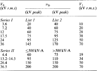

Table 35.3
Insulation co-ordination, 300–765 kV
| V0 (kV r.m.s.) | vsp (kV peak) | V1 (kV peak) |
| 300 | 750 | 850, 950 |
| 300 | 850 | 950, 1050 |
| 362 | 850 | 950, 1050 |
| 362 | 950 | 1050, 1175 |
| 420 | 950 | 1050, 1175 |
| 420 | 1050 | 1175, 1300, 1425 |
| 525 | 1050 | 1175, 1300, 1425 |
| 525 | 1175 | 1300, 1425, 1550 |
| 765 | 1300 | 1425, 1550, 1800 |
| 765 | 1425 | 1550, 1800, 2100 |
| 765 | 1550 | 1800, 1950, 2400 |
V0 highest system voltage (in kilovolts r.m.s.) at which the plant and the protective equipment have to operate normally;
v1p rated lightning-impulse withstand voltage (in kilovolts peak);
vsp rated switching-impulse withstand voltage (in kilovolts peak); and
V1 rated power-frequency short-duration withstand voltage (in kilovolts r.m.s.).
Lower range: Table 35.1 gives voltage values in two series based on current practice (I) in Europe and (II) in the USA and Canada, and applicable to other countries within the sphere of influence of (I) or (II). There are two lists in (I), the choice between them being made on consideration of the degree of exposure to lightning and switching impulse voltages, the type of system neutral earthing and (where applicable) the type of overvoltage protective devices. In (II) the data are based on the apparent power rating of the plant protected.
Middle range: In Table 35.2 more than one level of v1p is given, the highest being for plant in systems where the earth fault factor exceeds 1.4.
Higher range: Table 35.3 specifies no power-frequency values, the switching overvoltage having priority. The rated values of v1p associated with a standard vsp have been chosen in accordance with: (a) for plant protected by surge arresters the two lowest values apply, and (b) for plant not–or not effectively–protected by arresters only the highest value applies.
Several insulation levels may exist in the one power network, appropriate to different situations or to the characteristics of different protective equipments.
35.4.2 Protective equipment
Underground cables are virtually immune from direct lightning strokes, so that preventive measures apply in general only to overhead lines.
Earth wire: Shielding the line conductors by an earth wire is reasonably effective in preventing a direct stroke to the conductors, provided that the conductors lie within a segment subtending an angle of about 45° (or preferably 25° for towers above 50 m high) from the earth wire to the ground. Owing to the complex (and not fully understood) nature of the leader stroke as it approaches the earth, such protection sometimes fails; in cases of particular importance, e.g. near a major substation or where lightning is particularly prevalent, two earth wires may be installed.
Tower footing resistance: A lightning stroke to the earth wire can produce a back-flashover to the line conductors resulting in a line surge voltage unless the tower footing resistance is very low, e.g. not greater than 1 Ω per 100 kV of impulse level. In difficult situations a buried counterpoise earthing system, comprising wires radiating from the foot of the tower to a distance of 30–60 m, or continuous wires from tower to tower, help to lower the footing resistance.
35.4.2.2 Switching surges
While switching surges cannot be entirely avoided, it is desirable on lines of 300 kV upward to limit them by shunting across circuit-breaker contacts, during closure, resistors of value approximating to the surge impedance of the line (300–400 Ω).
35.4.2.3 Damage to plant
Overhead-line damage by overvoltage can occasionally occur, but is generally repairable fairly quickly, but damage to substation plant (particularly to transformers) is costly and results in a long outage. Overvoltage protection is thus aimed primarily at the defence of transformers.
Surge attenuation: A travelling wave of voltage attenuates (mainly by corona loss) as it is propagated along a line, and its magnitude and wavefront steepness are mitigated. Inductive coupling with the earth and with earth or counterpoise wires assists in this process. A reduction by one-half may thus occur in a line length of 5–8 km.
A length of underground cable between the terminal of an overhead line and the substation plant also reduces the magnitude of an incoming voltage surge, owing to the lower surge impedance of the cable. Additional reflections from the junctions may, however, partially offset this advantage and the cable is itself vulnerable. Although such a section of cable is often desirable for amenity or other reasons, it is rarely installed solely for protective purposes.
Surge arrester: The aim is to direct a surge to earth before it reaches a vulnerable plant. The arrester must be located as near as is practicable to the terminals of the plant. An ideal arrester (a) takes no current at normal system voltage, (b) establishes an instantaneous path to earth for any voltage that is abnormally high, (c) is capable of carrying the full discharge current and (d) inhibits subsequent power-frequency current. The modern device comprises an assembly of small gaps and non-linear resistors in series, the whole being contained in a cylindrical porcelain housing. The use of multiple rather than single gaps gives the most rapid breakdown. The resistor elements offer a low resistance to surge currents (limiting the voltage across the arrester) and a much higher resistance to the power-frequency follow current. Careful gap design ensures that the follow current does not restrike.
Rod gap: A plain air-gap is cheap, and it satisfies requirements (a), (b) and (c) above. However, it does not fulfil condition (d), and although gap breakdown protects the plant from overvoltage, there may be a power-frequency follow current which must be cleared by a circuit-breaker operation, involving an outage. A plain rod gap, connected between line and earth, has the following typical gap lengths giving breakdown at about 80% of the plant impulse level:
![]()
35.4.2.4 Prevention of outages
About 80% of the earth faults on overhead lines are of a transient nature resulting from lightning, birds or other causes, and no damage to the equipment is caused; however, the ionised path caused by the transient flashover permits a power-frequency follow current to flow which must be cleared by a circuit-breaker operation. Such outages can, however, be avoided in certain cases by the use of arc suppression coils (Petersen coils) or auto-reclose circuit-breakers.
Arc suppression coil: For reasons of insulation economy and/or safety it is customary to earth the neutral point of a system either directly or through a resistor. Any earth fault results in fault current and necessitates a circuit outage to clear it. Were the neutral point isolated, it might be expected that an earth fault would result in no fault current and that the system could continue to operate, provided that the raising of the two sound phases to line voltage above earth potential were acceptable. However, owing to the system capacitance a leading current will flow through the fault as shown in Figure 35.45(a). If the fault involves an arc, any such current, if it exceeds a few amperes, is likely to cause damaging voltage surges and to be very persistent. Operation with a completely isolated neutral point is therefore impracticable except on very small isolated systems.
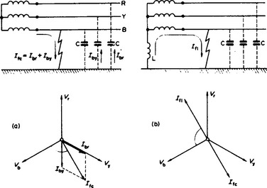
Figure 35.45 Action of arc-suppression coil: (a) isolated neutral; (b) neutral earthed through arc-suppression coil
If, however, the neutral is earthed through a high inductive reactance X (several hundred ohms), the resulting lagging current can, neglecting losses, precisely neutralise the capacitance current, as shown in Figure 35.45(b). There will thus be no fault current and the system can be operated with the fault until such time as it can conveniently be repaired. To secure precise balance the value of the arc suppression coil reactance must be X = 1/3ωC.
Arc suppression coils are effective on 12 kV, 36 kV and occasionally up to 245 kV systems, but at the higher voltages and with long lines the resistive and other losses prevent precise phase opposition of Ifl and Ifc so that there is a resultant current in the fault which, if it involves an arc, is inextinguishable and damaging.
Auto-reclose circuit-breaker: A transient flashover rarely causes damage if the fault is cleared by the normal protective equipment. After an interval of 0.4–0.8 s, sufficient for the natural de-ionisation of the arc path, the circuit-breaker can be reclosed with safety.
Circuit-breakers with automatic reclosure was widely used on 12 kV and 36 kV radial distribution networks. They are required to provide time delay switching in the event of a permanent fault; permit of normal fuse discrimination to limit the area of interruption; operate rapidly on the initial passage of a fault current. Figure 35.46(a) shows three applications. In (i) all transient faults are cleared by the recloser, and in the case of permanent faults the recloser sequence provides a time delay trip to blow the fuse only on the faulty sub-circuit. In (ii) sectionalisers provide the disconnecting means for faulty sub-circuits. Method (iii) operates as (i), except that on permanent fault the recloser holds closed and back-up protection operates.

A typical current operated recloser comprises a normally closed oil circuit-breaker for pole mounting. The breaker is held closed by springs. When the current exceeds, for example, twice full-load value, movement of the plunger of a series solenoid causes the recloser to open. The plunger is then spring-reset and the reclosing is automatic. Relay features control the reclosing and opening times, and a mechanism is provided to enable the recloser to lock open or hold closed at the end of its operating sequence.
Figure 35.46(b) shows a lock-open sequence, the open-circuit times being adjustable between 0.25 and 1 s. If the fault clears and operation is stopped during the cycle, the mechanism returns to the starting position. The ‘instantaneous’ trips are rapid (2–7 cycles) to avoid fuse deterioration: they give two chances for fault clearance. The time delay switching occurs twice to blow the fuses on a permanently faulted section. If the sequence continues, the operation terminates with the recloser locked open. In Figure 35.46(c) is shown a sequence ending in a hold-closed condition. A permanent fault is cleared by other means, after which the mechanism automatically resets. Transient faults are cleared as with type (b).
Where adequate fuse co-ordination is not obtainable, the alternative is the use of sectionalisers, as at (ii) in Figure 35.46(a), associated with automatic reclosers. A sectionaliser comprises a normally closed oil switch latched in against spring loading. When a fault occurs, the current passes through a series coil which actuates the mechanism and counts the fault current impulses during the recloser sequence, opening the sectionaliser automatically during a pre-set open-circuit period. The mechanism resets if the fault clears prior to the end of the sequence, but if the sectionaliser reaches the open condition, it must be reset by hand.
Auto-reclosing is also sometimes used on transmission systems to assist in maintaining stability by reclosing before synchronous machines have had time to lose synchronism. In some cases, particularly on single-circuit lines, the added complication of selecting, tripping and reclosing only the faulty phase is justified.
When the loss of supply may have serious consequences, duplicate supplies or a ring main may be installed.
Alstom, T. & D. Protective Relays Application Guide. Alstom T & D, Protection and Control Ltd; 1987.
Basak, P.K. et al., ‘Survey of TRV conditions on the CEGB 400 kV system’, lEE Proceedings, 128(6), 342–350
Blower, R.W., et al. Experience with Medium Voltage Vacuum Circuit-breaker Equipment E Conference Publication No 197). 1981:51–55.
Boggs, S.A. et al., Coupling Devices for the Detection of Partial Discharges in Gas-Insulated Switchgear (IEEE PES Paper 81 WM)
Chamia, M. ‘Transient behaviour of instrument transformers and associated high-speed distance and directional comparison protection’. Electra. 1980;72(October):115–139.
Chisholm, W.A., et al. ‘Lightning performance of overhead lines’. Ontario Hydro Review. 1981;3(January):19–24.
Chowdhuri, P. Electromagnetic Transients in Power Systems. Wiley; 1996.
Davy, R.A., et al. ‘State of the art in protection and control for ehv transmission’. Electrical Review. November 1980;207(19):27–29, 21.
Donon, J., Voisin, G., Factors Influencing the Ageing of Insulating Structures in SF6. GRE Paper 15-04). 1980:11.
Electricity Training Association. Power System Protection, a four volume text. IEE. 1997.
Flursheim, C.H. Power Curcuit Breakers-Theory and Design, Revised Edition. IEE. 1982.
Forrest, J.S., ‘Electricity supply–present and future’, IEE Electronics and Power, 29(11/12)
Gardner, G.E., et al. ‘Development testing techniques for air-blast and SF6 switchgear’. IEE Proceedings, Part C. September 1980;127(5):285–293.
14. IEE, Developments in Design and Performance of EHV Switching Equipment (lEE Conference Publication No. 182), Peter Peregrinus
15. IEE, Developments in Power System Protection (IEE Conference Publication No. 185), Peter Peregrinus
IEE. Electricity Distribution CIRED 1981) E Conference Publication No 197). Peter Peregrinus; 1981.
17. John, M.N., ‘Electricity supply–problems and possibilities’, lEE Electronics and Power, 29(10), 702–704
Johns, A.T., Salman, S.K. Digital Protection for Power Systems IEE, Power Engineering Books Series, 1995.
Johns, A.T., Walker, E.P. ‘Co-operative research in the engineenng and design of a new digital directional companson scheme’. Proceedings IEE, Part C. 135(4), July 1988.
Keinert, L, et al. Service Experience with and Development of SF6 Gas Circuit-Breakers Employing the Self-Extinguishing Principle E Conference Publication No 197). 1981:36–40.
Kriechbaum, K. ‘Progress in h v circuit-breaker engineering’. SRBE Bulletin. 1980;96(3-4):147–158.
Lat, M.V., et al. ‘Distribution arrester research’. IEEE PES Paper HWM 199-9. 9, 1981.
Latham, R.V. High-voltage Vacuum Insulation-tthe Physical Basis. Academic Press; 1981.
Maddock, B.J., et al. ‘Optical fibres in overhead power transmission systems for communication and control’. Proc. 29th International Wire and Cable Symposium USA. 1980:402–409.
Maller, V.N., et al. Advances in H V Insulation and Arc Interruption in SF6 and vacuum. London: Pergamon, Oxford; 1981.
Miller, T.J.E. Reactive Power Control in Electric Systems. Wiley Interscience; 1982.
Phadke, A.G., Thorp, J.S. Computer Relating for Power Systems. New York: Research Studies Press; 1988.
, ‘Surges in h v networks’. Ragaller, K., eds., Proc of Brown Boveri Symposium, 423, 1979.
Rosen, P. et al., ‘Recent advances in HRC fuse technology’, lEE Electronics and Power, 29(6), 495–498
Song, Y.H., Johns, A.T., Aggarwal, R.K. Computational Intelligence Applications in Power Systems. Wiley, New York: Science Press, Kluwer Academic Publishers; 1996.
Stamacka, E. ‘Interruption of small inductive currents’. Electra. 1980;72(October):73–103.
Tedford, D. J. et al., ‘Modern research and development in SF6 switchgear’, IEE Electronics and Power, 29(10), 719–723
in German . ‘The use of ZnO surge diverters in the Austrian ehv network’. Oesterrich Z Electr. December 1980;33(12):433–437.
Wright, A., Newbery, P.G., Electric Fuses. IEE, 2nd Edition. Power Engineering Books Series, 1995.