
Electrical Machine Drives
Fundamental control requirements for electrical machines 19.2
A.c. to d.c. power conversion 19.3.1
D.c. motor drive systems 19.3.2
D.c. to d.c. power conversion 19.3.3
A.c. to a.c. power converters with intermediate d.c. link 19.3.4
19.1 Introduction
It is now generally considered that 25–50% of all electrical power passes through semiconductor conversion. The importance of this technology is therefore self evident though the selection of appropriate equipment is often less clear. It would be a difficult, if not impossible, task to detail every power conversion circuit available, concentration will be given to those of greatest practical importance of the broad base of industry, particularly in the area of electrical variable speed drives.
In some respects semiconductor based power converters perform rather badly the functions of voltage and frequency changing which rotating machine based converters perform rather well. Economic and certain other factors are, in other than a few specialised applications, now so heavily in favour of electronic converters that only their performance will be considered.
Control philosophy and choice of semiconductor switching device are important aspects of any system but are sadly (from the standpoint of review) heavily dependent upon manufacturer. It is therefore useful to first consider the basic power conversion circuits, together with their inherent characteristics and then look at the available control strategies, their features and how they apply and impact upon converter systems. Basic power conversion circuits are considered in the Power Electronics chapter, however, it is helpful to consider salient circuits and characteristics here in the specific context of drives.
The existence of so many power conversion technologies reflects the diverse requirements industry demands. No single technology is the ‘optimum’ for all applications (despite some manufacturers’ claims). Good drive selection demands a good understanding of the application in regard torque/speed and dynamic characteristics together with the site environment. Simple guidelines are given.
Aspects of electrical variable speed drives vital for trouble free installation and ease of operation are also discussed. These include supply distortion/harmonics and communication systems the latter of growing importance for drives employed in an automated environment.
19.2 Fundamental control requirements for electrical machines
History will recognise the vital role played by d.c. motors in the development of industrial power transmission systems. The d.c. machine was the first practical device to convert electrical power into mechanical power, and vice versa in its generator form. Inherently straightforward operating characteristics, flexible performance and high efficiency encouraged the widespread use of d.c. motors in many types of industrial drive application.
The majority of standard d.c. motors, both wound-field and permanent-magnet, are now designed specifically to take advantage of rectified a.c. power supplies. Square, fully laminated frame construction allows minimal shaft centre height for a given power rating, and affords reduced magnetic losses, which in turn greatly improves commutating ability.
Over the last few years the use of permanent magnet motors, usually in the fractional to 3 kW range, has become commonplace in general-purpose drive applications. In this design the conventional wound field is replaced by permanent magnets bonded into the motor frame. The magnets have a curved face to offer a constant air gap to the conventional armature.
The circuit of a shunt-wound d.c. motor, Figure 19.1, shows the armature, armature resistance (Ra) and field winding. The armature supply voltage Va is supplied typically from a controlled thyristor system and the field supply voltage Vf from a separate bridge rectifier.
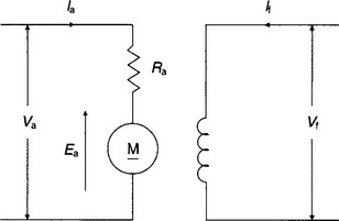
As the armature rotates an EMF Ea is induced in the armature circuit and is called the back-EMF since it opposes the applied voltage Va and the flow of current produced by Va. This back-EMF Ea is related to armature speed and main field flux by:
Also the applied, or terminal armature voltage Va is given by:
Multiplying each side of Equation (19.2) by Ia gives:
Total power supplied = Power output + Armature losses
Interaction of the field flux and armature flux produces an armature torque. Thus:
This confirms the straightforward and linear characteristic of the d.c. motor and consideration of these simple equations will show its controllability and inherent stability.
The speed characteristic of a motor is generally represented by curves of speed against input current or torque and its shape can be derived from Equations (19.1) and (19.2):
If the flux is held constant, which is achieved by simply holding the field current constant in a properly compensated motor then:
The circuits of Shunt wound and Series d.c. motors are shown in Figures 19.1 and 19.2 respectively.
With the Shunt motor the field flux Φ is only slightly affected by armature current, and the value of IaRa at full load rarely exceeds 5% of Va, giving a torque-speed curve shown typically in Figure 19.4(a), where speed remains sensibly constant over a wide range of load torque.

Figure 19.4 Torque/speed characteristic: (a) shunt wound d.c. motor; (b) compound d.c. motor; (c) series d.c. motor
The compound-wound d.c. machine combines the shunt and series characteristics. The circuits of the compound d.c. motors is shown in Figure 19.3.

The exact shape of the torque/speed characteristic is determined by the resistance values of the shunt and series fields. The slightly drooping characteristic, Figure 19.4(b), has the advantage in many applications of reducing the mechanical effects of shock loading.
The series motor curve, Figure 19.4(c), shows initial flux increase in proportion to current, falling away due to magnetic saturation. In addition the armature circuit includes the resistance of the field winding and the speed becomes roughly inversely proportional to the current. If the load falls to a low value the speed increases dramatically, which may be hazardous: the series motor should not normally be used where there is a possibility of load loss; but because it produces high values of torque at low speed and its characteristic is falling speed with load increase, it is useful in applications such as traction and hoisting or some mixing duties where initial friction is dominant.
The power speed limit for d.c. machine manufacture is approximately 3 × 10⁶ kW rev/min. This limit together with the maintenance attributable to d.c. motors can be blamed on the otherwise commendable commutator.
Under semiconductor converter control, with speed feedback from a tachogenerator, the shape of the speed/load curve is largely determined within the controller. It has become standard to use a plain shunt d.c. motor on the basis of reduced cost, even though the speed/load curve on open loop control is often slightly rising.
19.2.2 A.c. induction motor control
The a.c. squirrel cage induction motor is the basic, universal workhorse of industry, converting some 70–80% of all electrical power into mechanical energy. This type of motor nontheless exhibits some quite unattractive performance characteristics in spite of intensive development, notably instability and a non-linear load–current characteristic. It is invariably designed for fixed speed operation, larger ratings having such features as deep rotor bars to limit Direct on Line (DOL) starting currents. Electronic variable speed drive technology is able to provide the necessary variable voltage/current, variable frequency supply that the 3-phase a.c. machine requires for efficient, dynamic and stable variable speed control.
Modern electronic control technology is able not only to render the a.c. induction motor satisfactory for many modern drive applications but also to greatly extend its application and enable advantage to be taken of its low capital and maintenance costs. More striking still, microelectronic developments have made possible the highly dynamic operation of induction motors by the application of flux vector control. The practical effect is that it is now possible to drive an a.c. induction motor in such a way as to obtain a dynamic performance in all respects better than could be obtained with a phase controlled d.c. drive combination.
19.2.2.1 Fundamental equations and performance
Consider the stator winding of a simple three-phase 2-pole a.c. cage induction motor, each phase winding having only one slot per pole per phase as shown in Figure 19.5. End-connections for the winding coils are not shown, but R and R1 represent the start and finish of the red phase winding and similarly for the Y and B phase conductors. The R, Y and B phase windings are displaced 120° in space relative to one another.

Assuming that when stator current is positive it is flowing inwards in conductors R, Y and B, and therefore outwards in R1, Y1, B1; that the current in phase R in Figure 19.5(a), is at its maximum positive value and that in phase windings Y and B the currents at the same instant are negative and each equal to half maximum value: then these currents produce the magnetic fluxes represented in Figure 19.5(a) and the flux axis is horizontal.
Thirty degrees later in the supply cycle, the currents in phases R and B are 0.866 (![]() ) of their maximum, and zero in the Y phase. The pattern of the flux due to this current is shown in Figure 19.5(b). It will be noted that the axis of this field is now in line with coil Y–Y1 and therefore has turned clockwise through 30° from that of Figure 19.5(a).
) of their maximum, and zero in the Y phase. The pattern of the flux due to this current is shown in Figure 19.5(b). It will be noted that the axis of this field is now in line with coil Y–Y1 and therefore has turned clockwise through 30° from that of Figure 19.5(a).
After a further 30° in the supply cycle the current in phase winding B has reached maximum negative value, the currents in R and Y are both positive, at half their maximum value. These currents produce the magnetic flux shown in Figure 19.5(c), the flux axis being displaced clockwise by a further 30° compared with that of Figure 19.5(b).
Thus for every time-interval corresponding to 30° in the supply cycle, the axis of the flux in a 2-pole a.c. stator rotates 30° in space. With a 2-pole stator (one pair of poles) the flux rotates through one revolution in space in one cycle of the power supply. The magnetic flux is said to rotate at synchronous speed. The rotational speed of the flux is:
It is more usual to express speed in revolutions per minute:
60 · f/p revolutions per minute (r.p.m.)
The e.m.f. generated in a rotor conductor by transformer action is at a maximum in the region of maximum flux density. The e.m.f. generated in the single rotor conductor produces a current, the consequence being a force is exerted on the rotor tending to move it in the direction of the flux rotation. The higher the speed of the rotor, the lower the speed of the rotating stator flux field relative to the rotor winding, and therefore the smaller is the e.m.f. generated in the rotor winding.
If the speed of the rotor became the same as that of the rotating field, i.e. synchronous speed, the rotor conductors would be stationary in relation to the rotating flux. This would produce no e.m.f. and no rotor current and therefore no torque on the rotor. Because of friction and windage, the rotor could not continue to rotate at synchronous speed. The rotor speed must therefore fall below synchronous, and as it does so rotor e.m.f. and current, and therefore torque, will increase until it matches that required by the losses and by any load on the motor shaft.
The difference in rotor speed relative to that of the rotating stator flux is known as the slip. It is usual to express slip as a percentage of the synchronous speed. Slip is closely proportional to torque from zero to full load.
The most popular squirrel cage induction motor in sizes up to about 5 kW is of 4-pole design. Its synchronous speed with a 50 Hz supply is therefore:
Slip accounts for about 5%, and a typical nameplate speed is 1425 r.p.m.
Voltage—frequency relationship: If it is desired to convert a constant speed motor operating direct-on-line to a variable speed drive using an inverter it is necessary to consider the effect of frequency on flux and torque. An induction motor on a normal supply operates with a rotating field set up by three-phase currents in the stator winding. The magnitude of the field is controlled broadly by the voltage impressed upon the winding by the supply. This is because the resistance of the windings results in only a small voltage drop, even at full load current, and therefore in the steady-state the supply voltage must be balanced by the e.m.f. induced by the rotating field. This e.m.f. depends on the product of three factors:
(1) The total flux per pole (which is usually determined by the machine designer);
(2) The total number of turns per phase of the stator winding; and
Exactly the same factors are valid for transformer design, except that the field is pulsating instead of rotating. For inverter operator the speed of field rotation for which maximum voltage is appropriate is known as the ‘base speed’.
The consequence of reducing the supply frequency can readily be deduced from the relationship described above. For the same flux the induced e.m.f. in the stator winding will be proportional to frequency, hence the voltage supplied to the machine windings must be correspondingly reduced in order to avoid heavy saturation of the core. This is valid for changes in frequency over a wide range. The voltage/frequency relationship should therefore be linear if a constant flux is to be maintained within the machine, as the designer intended. If flux is constant so is the motor torque for a given stator current, hence the drive has a constant torque characteristic.
Although constant V/f control is an important underlying principle, it is appropriate to point out departures from it which are essential if a wide speed range is to be covered. Firstly, operation above base speed is easily achieved by increasing the output frequency of the inverter above the normal mains frequency; two or three times base speed is easily obtained. The output voltage of an inverter cannot usually be made higher than its input voltage therefore the V/f characteristic is typically like that shown in Figure 19.6(a). Since V is constant above base speed, the flux will fall as the frequency is increased after the output voltage limit is reached. The machine flux falls (Figure 19.6(b)) in direct proportion to the actual V/f ratio. Although this greatly reduces the core losses, the ability of the machine to produce torque is impaired and less mechanical load is needed to draw full load current from the inverter. The drive is said to have a constant-power characteristic above base speed. Many applications not requiring full torque at high speeds can make use of this extended speed range.

Figure 19.6 Voltage/frequency characteristics: (a) linear V/f below base speed; (b) typical motor flux with linear V/f (showing fall in flux at low frequency as well as above base speed); (c) modified V/f characteristic with low frequency boost (to compensate for stator resistance effects in steady state)
The second operating condition where departure from a constant V/f is beneficial is at very low speeds, whereby the voltage drop arising from the stator resistance becomes significantly large. This voltage drop is at the expense of flux, as shown in Figure 19.6(b). To maintain a truly constant flux within the machine the terminal voltage must be increased above the constant V/f value to compensate for the stator resistance effect. Indeed, as output frequency approaches zero, the optimum voltage becomes the voltage equal to the stator IR drop. Compensation for stator resistance is normally referred to as ‘voltage boost’ and almost all inverters offer some form of adjustment so that the degree of voltage boost can be matched to the actual winding resistance. It is normal for the boost to be gradually tapered to zero as the frequency progresses towards base speed. Figure 19.6(c) shows a typical scheme for tapered boost. It is important to appreciate that the level of voltage boost should increase if a high starting torque is required, since in this case the IR drop will be greater by virtue of the increased stator current. In this case automatic load-dependent boost control is useful in obtaining the desired low speed characteristics. Such a strategy is referred to as constant V/f (or V/Hz) control and is a feature of most commercially available a.c. drives though more advanced open-loop strategies are now becoming more available.
So far the techniques described have been based on achieving constant flux within the air gap of the machine or, if that is not possible, then the maximum flux. Constant flux is the ideal condition if the largest capability of torque is required because the load cannot be predicted with certainty, or if the most rapid possible acceleration time is desired. A large number of inverters are used however for variable air volume applications where control of airflow is obtained by variable speed fans. The torque required by a fan follows a square law characteristic with respect to speed and reducing the speed of a fan by 50% will reduce its torque requirement to only 25% of rated. As the load is entirely predictable there is no need for full torque capability and hence flux to be maintained, and higher motor efficiency can be obtained by operating at a reduced flux level. A further benefit is that acoustic noise, a major concern in air conditioning equipment, is significantly reduced. It is therefore common for inverters to have an alternative square law V/f characteristic or, ideally, a self-optimising economy feature so that rapid acceleration to meet a new speed demand is followed by settling to a highly efficient operating point.
Slip ring induction motor: The wound rotor or slip-ring a.c. machine whilst introducing the negative aspect of brushes does address some of the disadvantages of the cage induction motor but with the handicap of cost compared to the equivalent rated d.c. shunt-wound machine.
With the correct value of (usually) resistance inserted in the rotor circuit, near-unity relationship between torque and supply current at starting can be achieved, i.e. 100% full load torque, with 100% full load current, 200% FLT with 200% FLC etc., (i.e. comparable with the starting capability of the d.c. machine). Not only the high starting efficiency but also the smooth controlled acceleration historically gave the slip-ring motor great popularity for lift, hoist and crane applications. It has had similar popularity with fan engineers, to provide a limited range of air volume control, either 2:1 or 3:1 reduction, at constant load, by the use of speed regulating variable resistances in the rotor circuit. Although a fan possesses a square law torque–speed characteristic, so that motor currents fall considerably with speed, losses in the rotor regulator at lower motor speeds are still relatively high, severely limiting the useful speed range.
Rotor slip-ring systems, used with this type of motor, offer a similar service life to that of the d.c. motor commutator system.
Efficient variable speed control of slip-ring motors can be achieved by converters based upon the slip energy recovery principle first proposed by Krammer. Such schemes are based upon converting the slip frequency on the rotor to supply frequency. It is also possible to retrofit variable frequency inverters to existing slip-ring motors. This can be done simply by shorting out the slip-ring terminations (ideally on the rotor thereby eliminating the brushes) and treating the motor as a cage machine.
Variable voltage control of slip-ring motors has been used extensively, notably in crane and lift applications, though these are now largely being replaced by flux vector drives and will therefore not be considered further.
19.2.3 A.c. synchronous motors
A.c. induction motors produce shaft torque which is proportional to percentage slip, implying that with zero slip the machine produces zero torque. In a synchronous motor, torque can be produced at synchronous speed.
This is achieved by a field winding, generally wound on the rotor, and d.c. excited so that it produces a rotor flux which is stationary relative to the rotor. Torque is produced when the rotating three-phase field and the rotor field are stationary relative to each other, hence there must be physical rotation of the rotor at speed ns in order that its field travels in step with the stator field axis. At any other speed a rotor pole flux would approach alternately a stator north pole flux, then a south pole flux, changing the resulting torque from a positive to a negative value at a frequency related to the flux speed difference, the mean torque being zero.
A typical inverter for variable speed control automatically regulates the main stator voltage to be in proportion to motor frequency. It is possible to arrange an excitation control loop which monitors the main stator voltage and increases the excitation field voltage proportionately.
The a.c. synchronous motor appears to have some attractive features for inverter variable speed drive applications, particularly at ratings of 40 MW and above. Not least is overall cost when compared with an a.c. cage motor plus inverter, or d.c. shunt wound motor and converter alternatives. In applications requiring a synchronous speed relationship between multiple drives or precise speed control of single large drives the a.c. synchronous motor plus inverter control system appears attractive: freedom from brushgear maintenance, good working efficiency and power factor are the main considerations.
19.2.4 Brushless servomotors
The synchronous machine with permanent magnets on the rotor is the heart of the modern brushless servo motor.
The synchronous motor stays in synchronism with the supply, though there is a limit to the maximum torque which can be developed before the rotor is forced out of synchronism. ‘Pull out torque’ will be typically between 1.5 and 4 times the continuously rated torque. The torque-speed curve is therefore simply a vertical line, which indicates if we try to force the machine above the synchronous speed it will become a generator.
The industrial application of brushless servomotors has grown significantly for several reasons: reduction of price of power conversion products; establishment of advanced control of PWM inverters; development of new more powerful and easier to use permanent magnet materials; development of highly accurate position sensors, and the manufacture of all these components in a very compact form. They are, in principle, easy to control because the torque is generated in proportion to the current. In addition, they have high efficiency and high dynamic responses can be achieved.

Brushless servomotors are often called brushless d.c. servomotors because their structure is different from that of d.c. servomotors. Brushless servomotors rectify current by means of transistor switching within the associated drive/amplifier, instead of a commutator as used in d.c. servomotors. In order to confuse, brushless servomotors are also called a.c. servomotors because brushless servomotors of synchronous type with a permanent magnet rotor detect the position of the rotational magnetic field to control the three-phase current of the armature. It is now widely recognised that BRUSHLESS AC refers to a motor with a sinusoidal stator winding distribution which is designed for use on a sinusoidal or PWM inverter supply voltage. BRUSHLESS DC refers to a motor with a trapezoidal stator winding distribution which is designed for use on a square wave or block commutation inverter supply voltage.
The brushless servomotor lacks the commutator of the d.c. motor, and has a device (the drive sometimes referred to as the amplifier) for making the current flow according to the rotor position. In the d.c. motor, torque variation is reduced by increasing the number of commutator segments. In the brushless motor, torque variation is reduced by making the coil three-phase and, in the steady state, by controlling the current of each phase into a sine wave.
Stationary torque characteristics: A motor which uses permanent magnets to supply the field flux is represented by the simple equivalent circuit of Figure 19.8. This is a series circuit of the armature resistance, Ra, and back e.m.f., E.

If we ignore the voltage drop across the transistors, the equation for the voltage is
Ke is known as the back-e.m.f. constant of the motor. The armature current Ia is
Therefore, from above, the torque T is

Kt is known as the torque constant of the motor.
Figure 19.9 shows the relation between T (torque) and Ω (rotational speed) at two different voltages. The torque decreases linearly as the speed increases. The slope of this function is a constant KtKe/Ra and is independent of the terminal voltage and the speed. Such characteristics make the speed or position control of a d.c. motor relatively easy.

The starting torque and the no load speed (assuming no bearings friction and windage loss) are given by

19.2.5 Reluctance motors
The reluctance motor is arguably the simplest synchronous motor of all, the rotor consisting of a set of iron laminations shaped so that it tends to align itself with the field produced by the stator.
The stator winding is identical to that of a three phase induction motor. The rotor is different in that it contains saliency (a preferred path for the flux). This is the feature which tends to align the rotor with the rotating magnetic field making it a synchronous machine. The practical need to start the motor means that a form of ‘starting cage’ needs also to be incorporated into the rotor design, and the motor is started as an induction motor, which then the reluctance torque ‘pulls in’ the rotor to run synchronously in much the same way as a permanent magnet rotor.
Reluctance motors may be used on both fixed frequency (mains) supplies and inverter supplies. These motors tend to be one frame size larger than a similarly rated induction motor and have low power factor (perhaps as low as 0.4) and poor pull in performance. As a result of these limitations their industrial use has not been widespread except for some special applications such as textile machines where large numbers of reluctance motors may be connected to a single ‘bulk’ inverter and maintain synchronism. Even in this application, as the cost of inverters has reduced, bulk inverters are infrequently used and the reluctance motor is now rarely seen.
19.2.6 Switched reluctance motors
The SR motor is very different from the other polyphase machines described in that both the stator and the rotor have salient poles. The motor can only be used in conjunction with its specific power converter and control, and consequently only overall characteristics are relevant. SR drives are increasing in popularity. They are finding application in high volume appliances and industrial applications which can take good advantage of their charactristics notably high starting torque.
19.3 Drive power circuits
Converter circuits and their characteristics have been described in the Power Electronics chapter of this book. For convenience, the most important configurations used in drive systems are described here.
19.3.1 A.c. to d.c. power conversion
The three-phase controlled converters dominates all but the lowest powers where single-phase converters are used. Two power circuits are of practical importance:
• Fully controlled—This is by far the most important practical bridge arrangement. Figure 19.10 shows the power circuit together with associated a.c./d.c. relationships. Figure 19.11 shows how the d.c. voltage can be varied by adjusting the firing delay angle π. The pulse number, p, of this bridge equals 6. Energy flow can be from a.c. to d.c. or d.c. to a.c.


• Half Controlled—In this circuit either the top three devices of Figure 19.10 (Ap, Bp and Cp) or the bottom three devices (An, Bn and Cn) are replaced by diodes. The pulse number of this bridge equals 3. Only energy flow from a.c. to d.c. is possible. The voltage ripple is much greater than in the case of the fully controlled bridge, Figure 19.12, but the a.c. current drawn is lower at reduced d.c. voltage.

Summary of characteristics: Table 19.1 shows the salient characteristics of the three-phase a.c. to d.c. converters described above.

Practical effects: The characteristics in Table 19.1 have, for the most part, been based upon idealised conditions of negligible a.c. inductance and constant d.c. current. Whilst these assumptions provide a convenient means for compassion they are not often valid in practice. It is not practicable to consider all such effects here. The effect of d.c. link current ripple on a.c. supply harmonics is of great practical industrial importance mainly in relation to 3-phase bridges (ignoring single-phase traction requirement). Practical experience has led to the adoption by many of the following values:

In general, the amplitudes of higher harmonics are rarely of significance, in regard to supply distortion. Under conditions of very high d.c. current ripple, the 5th harmonic can assume a considerably higher value than that quoted above. A practical example would be an application with a very capacitive d.c. load (e.g. a voltage source inverter) in such a case where no smoothing choke is used I5 could be as high as 0.5I1.
19.3.2 D.c. motor drive systems
In principle little has changed since 1896 when Harry Ward Leonard presented his historic paper ‘Volts versus Ohms—the speed regulation of electric motors’. In practice, however, many advances have been made from auxiliary machines through mercury arc rectifiers to thyristors.
The d.c. motor is still the most versatile machine for variable-speed drive systems and is often the preferred choice when considerations such as freedom from maintenance or operation under adverse conditions are not paramount.
Earlier, it has been shown that complete control of a d.c. machine can be achieved by controlling the armature voltage, Va and the field current, If. Two power converters are employed for this purpose in most variable speed drives which employ the separately excited d.c. machine. (In referring to the number of converters in a drive, it is common to ignore the field converter—this nomenclature will be adopted below). It is relatively common in simple drives for the field converter to be a single-phase uncontrolled bridge thereby applying fixed field voltage.
In applications where the variation in motor resistance with temperature, or on sites with poorly regulated supplies, which results in unacceptable variations in field current, a controlled power converter is employed with current control. Such field controllers are further discussed later as applied to field weakening control.
Single converter drives: Figure 19.13 shows a single-converter d.c. drive.

In its most basic form the motor will drive the load in one direction only without braking or reverse running. It is said to be a ‘single-quadrant drive’, only operating in one quadrant of the torque-speed characteristic.
Such drives have wide application from simple machine tools to fans, pumps, extruders, agitators, printing machines etc.
If the drive is required to operate in both the forward and reverse directions and/or provide regenerative braking a single fully-controlled converter can still be used however, some means of reversing either the field or armature connections, as shown in Figure 19.14, must be added.

Reversal of armature current can involve bulky (high current) reversing switches but due to the low inductance of the armature circuit can be completed in typically 0.2 seconds. Field current reversal takes longer, typically in the order of 1 second, however lower cost reversing switches may be used. The field reversal time can be reduced by using higher voltage field converters to force the current. Forcing voltages up to 4 per unit are used but care must be taken not to overstress the machine. Obviously this increased voltage cannot be applied continuously and requires either a switched a.c. supply or a controlled field converter.
Armature and field reversal techniques are used where torque reversals are infrequent such as hoists, presses, lathes and centrifuges.
Dual-converter drives: When a four quadrant drive is required to change the direction of torque rapidly, the delays associated with reversing switches described above may be unacceptable. A dual converter comprising two fully controlled power converters connected in inverse-parallel can be used as shown in Figure 19.15. Bridge 1 conducts when the armature current Ia is required to be positive, bridge 2 when it is required to be negative.

There are two common forms of dual converter. In the first, both bridges are controlled simultaneously to give the same mean output voltage. However, the instantaneous voltages from the rectifying and inverting bridges cannot be identical, and reactors Lp are included to limit the current circulating between them. The principal advantage of this system is that when the motor torque, and hence current, is required to change direction (polarity), there need be no delay between the conduction of one bridge and the other. This is the dual converter bridge with circulating current.
In the other, the circulating current-free dual converter only one bridge at a time is allowed to conduct. The cost and losses associated with the Lp reactors can then be eliminated, and economies can also be made in the drive control circuits. However, the penalty is a short time delay, as the current passes through zero, while it is ensured that the thyristors in one bridge have safely turned off before those in the second are fired. This delay introduces a ‘torque-free’ period of typically 10 ms. Speed reversal for a 3 kW drive of this type from −1500 to +1500 rev/min can still be achieved in approx 200 ms.
This circulating current-free dual converter is by far the most common industrial four-quadrant drive and is used in many demanding applications—paper, plastics and textile machines where rapid control of tension is required, are good examples.
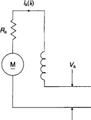
Field control: The output power of a motor is the product of torque and speed. If torque reduces in proportion to speed increases, the motor is said to have a constant power characteristic.
In applications where material is coiled or uncoiled at constant tension, the torque required to produce that tension varies in proportion to coil diameter, whilst rotational speed required to maintain a constant peripheral speed (and therefore line speed) is inversely proportional to diameter. A motor having a constant power characteristic is well suited to this type of application, the advantage being that a smaller motor can be used than would otherwise be the case. Machine tool drives also make use of constant power operation, since loads are small at high speeds, whilst heavy work is done at low speed.
The torque produced by a d.c. motor is proportional to the product of armature current and field flux. By weakening the field as speed increases, a constant power characteristic can be achieved.
In practice there are two major techniques for field weakening both of which rely on a field controller which itself is a simple thyristor converter operating in a current control mode.
In the first method, suitable for coiler and uncoiler applications, the field current reference is arranged to be inversely proportional to coil diameter (measured directly, or calculated from the ratio of line speed to motor speed). Since flux is not strictly proportional to field current, this method does not give a true constant-power characteristic unless compensation for the non-linear part of the motor field curve is applied.
The second method is to use the field controller with an outer, voltage loop having a fixed reference, and to use motor armature voltage as the feedback signal. At low speeds, the voltage loop saturates, providing maximum field current, since armature voltage is below the set value. As speed increases, the armature voltage rises to the point where it matches the preset reference in the field controller. Above that speed, an error signal is produced by the voltage loop, which causes the field controller to weaken the motor field current and thereby restore armature voltage to the setpoint level. The resulting characteristics are shown in Figure 19.16.

As regenerative braking depends on the return of power from the motor to the mains, it cannot work if the mains supply fails due to a blown fuse or a power cut. Dynamic braking of 4Q drives is often encountered as a fail-safe means of stopping the motor and its load, and as the only means of (reverse) braking of single-ended drives. This involves switching in a resistor across the d.c. motor.
Since the kinetic energy of the motor and its load is converted into heat by the braking resistor, it is important to rate it correctly for the duty it is expected to perform, taking account of load inertia and the number of stops per hour.
19.3.3 D.c. to d.c. power conversion
D.c–d.c. power converters (often refered to as ‘choppers’) provide the means to change one d.c. voltage to another. It is more usual for the conversion to be to a lower voltage, although step-up converters are available and have significant potential for the future.
D.c–d.c. power converters are fed from a d.c. supply usually comprising an uncontrolled a.c. to d.c. converter or alternatively a battery supply; the controlled d.c. output can then be used to control a d.c. machine as in the case of the controlled a.c. to d.c. converters.
D.c. drives employing controlled a.c. to d.c. converters have several important limitations which are overcome by the d.c–d.c. converter:
• The inability of a thyristor to interrupt current means that an alternating supply is necessary to commutate the converter—this precludes operation from a d.c. supply. This is a common requirement on battery vehicles and d.c. fed rail traction.
• The d.c. ripple frequency is determined by the a.c. and is, for a 50 Hz supply frequency, 100 Hz for single-phase and 300 Hz for three-phase fully-controlled bridges. This means that additional smoothing components are often required when using high speed machines, permanent magnet motors or other special motors with low armature inductance.
• As a result of the delay inherent in thyristor switching (3.3 ms in a 50 Hz 3-phase converter) the current control loop band width of the converter is limited to approximately 100 Hz, which is too low for many servo drive applications.
• Thyristor controlled a.c.–d.c. converters have an inherently poor input power factor at low output voltages. (Near unity power factor can be achieved using an uncontrolled rectifier feeding a d.c.–d.c. converter).
• Electronic short-circuit protection is not economically possible with thyristor converters. Protection is normally accomplished by fuses.
D.c–d.c converters are however more complex and somewhat less efficient than a.c.–d.c. converters. They find application mainly in d.c. servodrives, rail traction drives and small fractional kW drives employing permanent magnet motors.
Since step-down converters are of greatest practical importance emphasis shall be placed on their consideration. For the purpose of illustration bipolar transistors will be considered however MOSFET, IGBT and GTO’s are widely used.
19.3.3.2 Step-down d.c.–d.c. converters
Single-quadrant d.c.–d.c. converter: The most basic d.c. to d.c. converter is shown in Figure 19.17. The output voltage is changed by pulse-width modulation (PWM)—that is, by varying the time for which the transistor T is turned on. The voltage applied to the motor is therefore in the form of a square wave of varying periodicity. Because the motor is inductive the current waveform is smoothed, the flywheel diode D carrying the current whilst the transistor is turned off.

The basic formulae relating the variables in this circuit are as follows:

The circuit is only capable of supplying unidirectional current and voltage to the motor and is therefore not capable of four-quadrant operation, that is reversing or regenerating.
Applications for this circuit are normally limited to drives below 5 kW and simple variable-speed applications.
Two-quadrant d.c.–d.c. converter: In order to achieve full four-quadrant operation a converter must be capable of supplying reversible voltage and current to the motor. A circuit that is capable of two-quadrant operation—that is motoring and braking in one direction only—is shown in Figure 19.18. This converter is able to reverse the current flow to the motor but unable to reverse the motor terminal voltage and hence the speed. During motoring, the converter operates as the basic ‘chopper’ with T1 and D2 carrying the current. During braking (or regeneration) T1 is inoperative and T2 controls the current. During its on-periods, motor current builds up negatively, limited by motor inductance L. When T2 turns off, the only path for the current is via D1 back into the supply; hence the circuit is regenerative.

Since this circuit is not capable of motor speed reversal it is normally only used in unidirectional applications. However because of its simplicity it is sometimes used in traction applications where reversing is carried out by means of a changeover switch to reverse the armature or field supply.
Four-quadrant d.c.–d.c. converter: Figure 19.19 shows a basic four-quadrant converter capable of supplying reversible voltage and current i.e. of reversing and regeneration.

During motoring, positive output transistors T1 and T4 are switched on during the on-period, whilst diodes D2 and D4 conduct during the off-period. When D2 and D4 conduct, the motor supply is reversed and consequently the voltage is reduced to zero at 50% duty cycle. Any reduction of duty cycle below 50% will cause the output voltage to reverse but with current in the same direction; hence the speed is reversed and the drive is regenerating. With transistors T2 and T3 conducting, the current is reversed and hence the full four-quadrant operation is obtained.
One disadvantage of this converter is that the amplitude of the output ripple voltage is twice that of the simple converter—and the current ripple is therefore worse. This problem can be overcome by a technique known as double-edged modulation. With this technique the flywheel current is circulated via a transistor and a diode during the off-period. For example, after T1 and T4 have been conducting, T4 is turned off and T3 on, so that the flywheel current circulates via T1 and D3. The net effect is a reduction in ripple voltage and a doubling of ripple frequency.
These four-quadrant converters are widely used in high performance d.c. drives such as servos.
19.3.3.3 Step-up d.c.–d.c. converters
As with step down converters many alternative configurations exist for step-up converters. Whilst a full description is not necessary, the principle is of value.
Figure 19.20 shows a much simplified arrangement of a step-up converter. When T is turned on, current builds up in inductor L. When T is turned off, the energy stored in L is transferred to Capacitor C via D. When the capacitor voltage, which is the same as the motor armature voltage reaches the desired level, T is turned on once more. C cannot discharge via T as diode D is reverse biased.

In this way a stabilised voltage typically twice the input d.c. voltage can be obtained. This circuit is particularly useful when operating on low voltage supplies and can lead to very cost effective converter designs.
19.3.4 A.c. to a.c. power converters with intermediate d.c. link
This catagory of a.c. drive commonly termed ‘Variable Frequency Inverters’ is by far the most important in respect of the majority of industrial applications. It is being considered here as a complete converter, however the input stages have been considered earlier in isolation, and their individual characteristics so described are, of course, applicable. Alternative input stages to some of the drives are applicable.
Also some converters may be used with a variety of machine types. Only practically important combinations are described.
The concept of these ‘inverter’ drives is well understood—‘rectification of fixed frequency, smoothing and then inverting to give variable frequency/variable voltage to feed an a.c. machine’. Within this broad concept two major catagories of drive exist: Firstly, voltage source in which the converter impresses a voltage on the machine, and the machine impedances determine the current. Secondly, current source in which the converter impresses a current on the machine, and the machine impedances determine the voltage.
19.3.4.1 Voltage source inverters
General characteristics: The fixed frequency mains supply is a voltage source behind an impedance. Voltage source inverters can be similarly considered, and consequently are very flexible in their application. Major inherent features included:
• Multi-motor loads can be applied—this can be very economical in applications such as roller table drives, spinning machines etc.
• Inverter operation is not dependent upon the machine—indeed various machines (induction, synchronous or even reluctance) can be used provided the current drawn is within the current rating of the inverter. Care should be taken where a low power factor motor is used (e.g. reluctance) to ensure the inverter can provide the required VARs.
• Inherent open-circuit protection, very useful in applications where the cables between the inverter and motor are in some way insecure (e.g. fed via slip-rings, subject to damage etc.).
• Facility to ‘ride-through’ mains dips can easily be provided by buffering the d.c. voltage link with capacitance or, where necessary, a battery.
• Motoring operation only in both directions is possible without the addition of resistive dumps for braking energy or expensive regenerative converters to feed energy back to the supply.
Six step square wave inverter: A typical d.c. link square wave voltage-fed inverter drive is shown in Figure 19.21. The three-phase a.c. supply is converted to d.c. in the phase-controlled rectifier stage. The rectified d.c. power is then filtered and fed to the inverter. Note that the d.c. link reactor is small compared to that used in current source designs. Indeed in drives up to about 4 kW it is not practically necessary. Some manufacturers omit the reactor in designs to 400 kW and above, however this has a significant effect upon supply harmonics and unduly stresses the rectifier and filter capacitor.

The inverter switching elements shown as transistors TR1 to TR6 are gated at 60° intervals in the sequence in which they are numbered in the diagram, and each transistor conducts for 180°. The feedback diodes D1 to D6 are connected in inverse-parallel with the transistors, and permit the return of energy from reactive or regenerative loads through the inverter to the d.c. link.
For a star-connected motor, synthesis of inverter output voltage waveforms is shown in Figure 19.22. The phase-to-neutral voltage of the inverter has six-step waveshape while the corresponding phase-to-phase voltage has 120° conduction angle. The output frequency is controlled by the rate at which the inverter transistors are triggered into conduction by the inverter control circuitry. Reversing the firing sequence of transistors in the inverter changes the direction of rotation of the motor, and no switching of power leads, either on the incoming supply or to the motor itself, is necessary.

The phase-controlled rectifier regulates the d.c. link voltage and this, in turn, determines the magnitude of the output voltage from the inverter. Thus, the output voltage/frequency relationship may be controlled to regulate the motor flux in the desired manner.
The advantages of the square-wave inverter are high efficiency (98%), suitability to standard motors, potential good reliability and high-speed capability. However, it suffers from low-speed torque pulsations and possible low-speed instability.
In a square wave inverter, each harmonic voltage amplitude is inversely proportional to the harmonic order and hence there are no pronounced high-order harmonics. These are filtered by the motor leakage inductances.
Very high speed motor operation is possible by increasing the output frequency. Faster switching devices such as MOS transistors and insulated gate bipolar transistor (IGBT) can be used to achieve this performance.
It is known that the square wave inverter gives objectionable torque pulsation at low frequency operation, below approximately 5 Hz. This pulsating torque is due to the interactions of low order harmonics with the fundamental voltage, causing a stepping or cogging motion to the rotor running at low speed. Hence, the pulsating torque limits the low frequency operation of the square wave inverter. Appropriate feedback control techniques or flux weakening can attenuate the low speed pulsating torque problems.
The existence of a phase-controlled rectifier to control the voltage of the inverter as illustrated in Figure 19.21 is an inherent weakness of this circuit. The phase-controlled rectifier will present a low power factor to the a.c. supply, at low speeds, and the d.c. link filter capacitor is large and reduces the response time of the system to voltage and hence speed changes. If the drive system is one for which regenerative braking operation is a requirement, the rectifier has to be of inverse-parallel type. The input power-factor and response time of the drive can be improved by replacing the phase-controlled rectifier with a diode rectifier feeding a d.c. chopper which regulates the input voltage to the inverter. For recovering regenerative energy of the load, a two-quadrant chopper will be necessary. The alternative supply converter arrangement of a diode bridge plus chopper also provides a fixed voltage link which is more economically buffered if mains dip ride-through is required.
The voltage-fed square-wave drive is usually used in low power industrial applications where the speed range is limited to 10 to one and dynamic performance is not important. Recently, this type of drive has largely been superseded by PWM type voltage-fed inverters. Nevertheless, the voltage-fed square wave inverter can be easily adapted to multimotor drives where the speed of a number of induction motors can be closely tracked. It is also used in some high frequency (> 1 kHz) and some high power applications.
Pulse width modulated (PWM) inverter: In the PWM inverter drive, the d.c. link voltage is uncontrolled and derived from a simple diode bridge. The output voltage can be controlled electronically within the inverter by using PWM techniques. In this method, the transistors are switched on and off many times within a half cycle to generate a variable-voltage output which is normally low in harmonic content.
A PWM waveform is illustrated in Figure 19.23.

A large number of PWM techniques exist each having different performance notably in respect to the stability and audible noise of the driven motor.
Using the PWM technique, low-speed torque pulsations are virtually eliminated since negligible low-order harmonics are present. Hence, this is an ideal solution where a drive system is to be used across a wide speed range.
Since voltage and frequency are both controlled with the PWM quick response to changes in demand voltage and frequency can be achieved. Furthermore, with a diode rectifier as the input circuit a high power-factor, approaching unity, is offered to the incoming a.c. supply over the entire speed and load range.
PWM inverter drive efficiency typically approaches 98% but this figure is heavily affected by the choice of switching frequency—the higher the switching frequency the higher the losses in the drive. In practice the maximum fundamental output frequency is usually restricted to 100 Hz in the case of gate turn-off thyristors (GTO) or about 1 kHz for a transistor based system. The upper frequency limit may be improved by making a transition to a less sophisticated PWM waveform with a lower switching frequency and ultimately to a square wave if the application demands it. However, with the introduction of faster-switching power semiconductors, these restrictions to switching frequency and minimum pulse-width have been eased.
In general, a motor with a large leakage reactance is desirable to limit the flow of harmonic currents and thereby minimise losses.
19.3.4.2 Current source inverters
Whereas each voltage feeding inverter can be used with most forms of a.c. machine, a different design is usually adopted for synchronous and induction motors. Current source drives are usually, but not always, single-motor systems, and since current is controlled, have simple short-circuit protection.
In contrast to voltage source inverters full four quadrant operation is inherently possible.
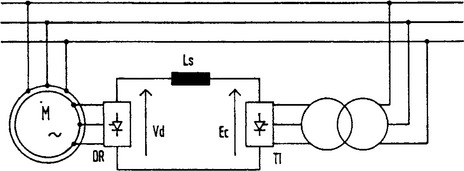
Converter-fed synchronous machine: Once rotating a synchronous machine generates a.c. voltages which can be used for the natural commutation of a converter connected to its terminals. Indeed the connected synchronous machine behaves as the mains in respect of the a.c to d.c converters described earlier.
Figure 19.24 shows the basic components of the drive system. A low-impedance or ‘stiff’ d.c. current source is required and is obtained from a controlled rectifier and a series reactor. With a stiff current source, the output current wave is not greatly affected by the magnitude of the load.

The synchronous machine can be approximately represented by a counter-emf in series with an equivalent leakage inductance. The d.c. current is switched through the inverter thyristors so as to establish three-phase, six-stepped symmetrical line current waves. Each thyristor conducts for 120° and at any instant one upper thyristor and one lower thyristor remain in conduction.
It is necessary to maintain an approximately constant angular relationship between the rotor and stator m.m.f.s and hence automatically maintain the correct inverter frequency. This is an important point. The inverter does not impose a frequency upon the machine, rather the machine itself determines the frequency. The motor cannot therefore pole-slip. The drive is accelerated by increasing the current fed to the drive which then accelerates and thereby increases the frequency.
As in the d.c. drives, the a.c. supply power factor is poor at low speeds. Full four-quadrant operation is possible without additional components.
Special procedures are necessary for starting these drives since at standstill the machine voltage is not available to commutate the current. In essence this is usually achieved by momentarily switching off the d.c. link current every sixth of a cycle. This allows the thyristors in the inverter to turn off so that the next pair can be fired. Above approximately 5% of rated speed the machine generates sufficient voltage for natural commutation and control is undertaken in a similar manner to that of a d.c. drive.
Applications for this type of drive fall into two main catagories. Firstly, starting converters for large synchronous machines, the converter being rated only for a fraction of the machine rating. Secondly, as large high power (and sometimes high speed) variable speed drives for a variety of applications. Power ratings, typically from 1.5 to 30 MW at speeds up to 8000 rpm are available. Also of import is the fact that high voltage drives are offered with supply voltages up to 5 kV typical, but systems up to 25 kV are in service where the high voltage converter technology is similar to that used for HVDC power converters.
Converter-fed induction motor drive: Unlike the Synchronous machine, the induction motor is unable to provide the VARs, or terminal voltage to commutate a converter connected to its terminals. Commercial schemes are available however which are closely based upon the converter fed synchronous machine drive having additional components to provide VAR compensation.
Figure 19.25 shows a basic power circuit. The diagram somewhat belies the potential complexity of the VAR compensator. In its simplest form this could comprise capacitors plus appropriate switches. Control of such a system is somewhat involved. It is often better to use a cycloconverter or even an auxiliary synchronous machine to provide the commutation, and motor VARs.

This system is only appropriate for high power drives, generally above 4 MW where an induction motor is preferred.
Forced commutated induction motor drive: This is the most widely used current source inverter at power levels in the range 50–3500 kW at voltages up to normally 690 V. (High voltage versions 3.3 kV/6.6 kV have been developed however they have not proved to be economically attractive.)
Figure 19.26 shows the inverter and motor of the drive. The d.c. link current Id, taken from a ‘stiff’ current source is sequentially switched at the required frequency into the stator windings of the induction motor. The motor voltage waveform is approximately sinusoidal apart from the superposition of voltage spikes caused by the rise and fall of machine current at each commutation. Further distortion is caused by the effects of slot ripple and d.c. current ripple.

The operating frequency range is typically 5-60 Hz, the upper limit being set by the relatively slow commutation process. Special motors with low leakage inductance do offer advantage with this converter and allow reduced capacitance in the inverter and/or higher operating frequency. Below 5 Hz, torque pulsations can be problematic but PWM of the current can be used at low frequencies to ease the problem.
This system is most commonly used for single motor applications such as fans, pumps, extruders, compressors etc. where very good dynamic performance is not necessary and a supply power factor which decreases with speed is acceptable.
Static Kramer drive: The static Kramer drive is shown in Figure 19.27. The drive comprises a slip-ring (wound rotor) induction motor together with an uncontrolled converter, d.c. smoothing reactor and a fully-controlled converter in the rotor circuit.
The diode bridge gives an output voltage Vd which is proportional to the slip of the motor. Vd is opposed by the d.c. voltage of the fully-controlled bridge, a small potential difference being sufficient to circulate current corresponding to the required load torque. Ideally, neglecting losses, the fully-controlled bridge d.c. voltage sets the speed to which the motor will accelerate. Control is therefore very similar to a d.c. drive.
Power can flow in only one direction via the diode bridge which means that motoring torque can be developed only at subsynchronous speeds. For reverse running it is necessary to reverse the phase sequence of the stator supply.
This drive can be very economic when designed for operation over a limited speed range below synchronous speed—this is the useful operating region for fans, pumps etc. The converter bridges required for such limited speed range operation need only be rated at a fraction of that of the machine it is controlling. It is necessary in such designs to provide a starter, usually a resistance to run the motor up to the lowest controllable speed. This means that should there be a fault with the converter equipment, the system can be easily designed to run at full speed without the controller.
Note that the supply harmonic currents and VARS associated with the converter part of the drive may be substantially reduced by adopting a limited speed range solution.
The static Kramer drive finds application mainly at ratings between 1 and 20 MW, with induction motors with 4 or more poles. (Stability problems exist with 2-pole motors which can only be resolved with care.) Speed ranges of 30% are typical (i.e. 70–100% rated speed). The induction motor stator can be wound for any conventional voltage e.g. 6.6 kV, 11 kV.
19.3.5 Direct a.c. to a.c. power converters
This final catagory of power converters converts the fixed frequency, fixed voltage a.c. supply to a variable frequency and/or variable voltage without an intermediate d.c. link.
19.3.5.1 Soft starter/voltage regulator
Figure 19.28, shows a typical soft start comprising inverse parallel connected thyristors in each supply line to an induction motor. Alternative connections are available but the principles are similar. The converter is used to control the voltage applied to the motor and in this way ‘soften’ the effects of switching an induction motor direct-on-line (DOL). Whilst the converter will control the current drawn from the supply, its most usual application is in controlling torque to provide smooth ‘jolt’ free acceleration.

Because the stator frequency is unchanged, a reduced running voltage, and hence flux, equates to a large slip which results in additional rotor losses—care must therefore be taken in its application.
In a number of specialised cases, purpose designed high resistance rotors (or slip-ring motors with external rotor resistors) are used to form a variable speed drive—the rational for such a system is based more on history than technology.
More recently such converters have been employed as combined soft starters/power-factor controllers/energy saving devices. The case for significant energy saving by this form of converter is often hard to prove.
A crude form of frequency control is possible by modulating (varying cyclically) the thyristor firing angles at the required output frequency. Whilst commercial systems are available they are of limited value since supply current and motor torque are of poor quality.
19.3.5.2 Cycloconverter
A typical scheme for a cycloconverter drive is shown in Figure 19.29. Each motor phase is supplied, in effect, from a dual a.c. to d.c. converter which was described earlier. It is usual to employ circulating current-free converters. To avoid line to line short-circuits isolating transformers are used on the supply side. By modulating the firing angles of the dual bridge converters, a controllable three-phase set of voltages can be produced suitable for feeding polyphase a.c. machines.

The drive is inherently 4-quadrant. The maximum output frequency is limited to approximately half the supply frequency by considerations related to harmonics in the motor currents and torque, stability and dimensions of the drive components. The cycloconverter therefore finds application in low-speed drives. The complexity of the drive also means that only high power systems (>1 MW), or specialised applications (e.g. conveyor drives for use in hazardous environments) are economic.
They are used on large ball mills, minewinders etc. They are also used to feed multimotor loads such as roller tables.
Due to the modulation of the converter firing angles, the harmonic content of the a.c. supply is complex and designs for appropriate harmonic filters somewhat involved.
The cycloconverter is suitable for feeding both induction and synchronous machines. In specialised applications such as wind generators, cycloconverters have been placed in the rotor circuit of a slip-ring induction motor. Such a system, known as a static Scherbius drive which is detailed below.
19.3.5.3 Static Scherbius drive
The static Scherbius drive is closely related to the static Kramer drive, with the single quadrant diode bridge in the rotor circuit replaced by a cycloconverter.
The cycloconverter is used as the voltage and frequency changer between the rotor and the supply. The cycloconverter is inherently regenerative, and the output can be controlled up to half the supply frequency in both phase sequences. It is thus possible for the system to operate as a full 4-quadrant drive. For a given converter rating the range of speed control is therefore twice that of a static Kramer drive.
The relative complexity of the drive limits its application to somewhat specialised high power applications where a very limited speed range only is required and perhaps stringent harmonic current limits have been imposed by the supply authority.
19.3.5.4 Matrix converter
Recently attention has been refocused on the matrix converter shown in Figure 19.30. Whilst the basic circuit is not new, recent advances in power devices offer the potential to overcome many of the drawbacks inherent in the circuit when the switches comprise inverse parallel thyristors. Limitations in the maximum output voltage (86% input) means that its application in the commercial industrial market could be problematic. There are prospects in regard to integrated motors and some servo systems where machine voltage is not seen as critical.

Commercial systems are available only for very specialised applications at present. It has yet to be proven to be a practical and cost effective industrial drive although some major drives companies are working on this technology.
19.4 Drive control
Most medium and large size industrial d.c. motor drives are based on a separately excited motor. The flux is generated by a field winding and the torque by a higher current armature winding fed via a commutator. These two windings are completely independent, and so the flux and torque can be controlled independently as shown below in Figure 19.31(a). Although the field winding usually has a long time constant, the armature winding time constant is normally very short allowing fast changes of armature current and hence torque.

Flux controller: The field converter is either a half or fully controlled thyristor converter. The half controlled converter can only apply positive voltage to the field winding, and so the current in the winding can be increased quickly, but decays slowly. The fully controlled converter can apply positive or negative voltages, and so the performance is the same whether the current is increasing or decreasing. When the motor is rotating at a speed below base speed the field current reference is constant at the rated level for the motor, and so the motor armature voltage increases with speed. The armature voltage reaches its rated level at base speed, and above this speed the flux controller reduces the field current reference, i*F to keep the voltage at the rated level as the speed increases further. The armature voltage feedback can include armature resistance compensation to avoid the effects of the armature resistance drop on the voltage control loop.
Torque controller: For four-quadrant operation two thyristor bridges are used as shown in Figure 19.31(b). Both bridges can apply positive or negative voltage to the motor, but the positive bridge can only supply positive current and the negative bridge negative current. Therefore the positive bridge conducts when positive torque is required and the negative bridge when negative torque is required. The bridges are phase controlled to apply the voltages required by the reference, VA*, to the motor. Due to the high voltage ripple in the converter output and the unidirectional nature of thyristors, the current in the armature can be continuous or discontinuous. While the current is continuous the relationship between the voltage reference and the actual applied voltage is a cosine function and the voltage reference can be used directly to control the firing angle of the converter. When the current is discontinuous the relationship is highly non-linear and varies with the voltage level applied to the motor. The drive stores the relationship between the firing angle and motor current for different output voltage levels, and during discontinuous current operation the correct firing angle is selected by the firing angle prediction block for a given current reference. Any errors are trimmed out by an integrator operating on the current error.
When a change in direction of torque is required one bridge must stop conducting and the other bridge must become active. It is clear from the power circuit diagram that only one bridge must conduct at a time during this changeover to avoid a short circuit across the armature supply. It is important that this changeover occurs as quickly as possible to give good dynamic torque control. Modern microprocessor controlled drives enable intelligent methods to be used to keep the bridge changeover delay as short as possible.
Performance and applications: The performance characteristics of a d.c. motor drive can be summarised as:
• The current controller sample rate is limited by the possible commutation rate of the thyristors in the bridges. In general the sample rate and hence the bandwidth of a d.c. drive is ten times lower than that of an a.c. drive.
• The d.c. drive with separately excited d.c. motor is used in similar applications to closed-loop induction motor drives. Because the flux and torque are controlled by separate winding, the decoupling of flux and torque control is not dependent on knowledge of the motor parameters. Therefore accurate control of torque is more easily achieved.
• The thyristor power circuits used in a d.c. drive cost less than an IGBT inverter for an a.c. drive of equivalent power rating. However, a d.c. motor is more expensive than an a.c. motor of equivalent power rating, at power ratings below approximately 200 kW. In general d.c. motors require more maintenance than a.c. motors.
• A full four-quadrant d.c. drive can be constructed with two thyristor bridges, however, the input power factor is poor. A full four-quadrant a.c. drive using an input converter as described above takes currents with significantly less harmonics and with almost unity displacement factor.
• The drive can be used in torque control, without the speed controller.
Although it has been predicted for many years that a.c. drives would replace d.c. drives, this has only happened slowly and many d.c. drives are still manufactured. These are used in many industrial applications especially in larger sizes. The following are some examples of where d.c. drives are used.
19.4.2 A.c. drive control
There are many types of variable speed drive each suited to different applications or for operation with different types of motor. In this section descriptions are given of typical control systems for a range of different types of variable speed drive operating with a.c. motors
19.4.2.1 General purpose open-loop a.c. drive
The open-loop a.c. drive is a high power variable frequency voltage source. In its simplest form, the output frequency is defined by the user’s reference and a suitable fixed frequency to voltage characteristic used to define the output voltage. Although this type of drive is normally designed to supply one or more induction motors connected in parallel, it can also supply other types of a.c. motor or it can be used as a variable frequency/variable voltage power supply. The following description relates to the operation of an open-loop a.c. drive with an induction motor.
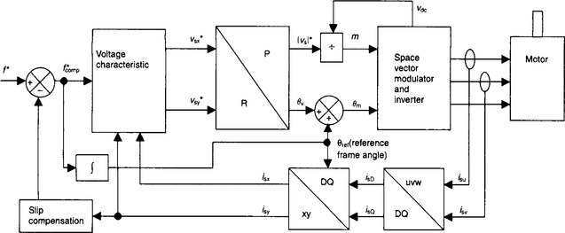
Figure 19.32 shows a block diagram of a typical general purpose open-loop drive. For this type of control system feedback is required from the output current of at least two phases of the inverter and the voltage from the d.c. side of the inverter. These feedback signals can be derived from within the drive itself, and so no external feedback, such as the motor speed or position, is required. The control system allows a simple ‘open-loop vector strategy’ to be implemented. In common with all other a.c. drive control strategies described in this chapter the control system is based on a ‘reference frame’.
Performance and applications: The performance characteristics of the open-loop drive control system applied to an induction motor can be summarised as:
• Moderate transient performance.
• Full torque production down to approximately 3% of rated motor speed.
• Although a good estimate of stator resistance (Rs) improves torque production at low speeds, the control system will work with an inaccurate estimate, albeit with reduced torque. The stator resistance can be measured by the drive with a simple test.
• Although a good estimate of motor slip improves the ability of the drive to hold the reference speed, the control system will work with an inaccurate estimate, albeit with poorer speed holding. The motor slip depends on the rotor time constant of the motor (Tr) and this cannot be measured easily.
• No position or speed feedback is required from the motor shaft.
This type of drive is used in many applications where moderate performance is required and where providing position feedback would be unacceptable because of the environment or cost, or is simply not necessary. The following are some examples of applications where open-loop drives are used:
19.4.2.2 Closed-loop induction motor drive
The closed-loop induction motor drive, often referred to as a closed-loop vector drive, is used in many applications requiring better performance than an open-loop drive with an induction motor. To obtain the best performance with this type of drive position feedback is required from the rotor, but unlike the permanent magnet servo drive only the change of position and not the absolute position is required. The control system is similar to that used with a permanent magnet servo motor as shown below.
Performance and applications: The performance characteristics of the closed-loop induction motor drive can be summarised as:
• Good dynamic performance at all speeds.
• Full torque operation down to standstill.
• A position feedback device that gives the incremental position of the rotor is required.
• Wide power range of motors available so that this type of drive can be used for applications requiring less than 1 kW up to more than 1 MW.
• Suitable for field weakening applications where motors can be operated up to many times base speed.
• The drive can be used in torque control, without the speed controller. The estimate of the flux position to align the reference frame is important as this affects the absolute level of torque produced for a given torque reference. The flux position calculation is dependent on an estimate of the rotor time constant which varies significantly with rotor temperature. However it is possible to include a rotor time constant estimator in the drive control system, so that the drive gives consistent torque control.
Closed-loop induction motor drives are used in many applications where good dynamic performance is required and especially where an induction motor drive is required to give full torque at standstill. The following are some examples of applications where this type of drive is used:
Operation without position feedback: The control system described above requires incremental rotor position feedback, but it is possible to implement the scheme without any physical feedback device. This can be done by estimating the rotor position from information available to the drive through the motor voltages and currents. One class of methods used to determine the rotor position, referred to as model based methods, use a model of the motor to calculate the rotor speed and hence the incremental rotor position. When a physical position feedback device is used the drive gives good dynamic performance and operates with full torque even at standstill. When a position estimator is used the dynamic performance is reduced and the minimum speed for full torque operation is similar to that of the open-loop drive. However a closed-loop induction motor drive without position feedback does have the following advantages and disadvantages when compared to an open-loop induction motor drive.
• Light load instability problems that can occur with an open-loop drive are eliminated.
• Torque control operation is improved.
• Starting with a spinning motor is faster.
• Fast closed-loop current control reduces trips under transient conditions.
• The motor model is normally dependent on the stator resistance and the rotor time constant. Incorrect estimates of these parameters can cause a significant reduction in performance and low speeds. Without real position feedback information it is difficult for the drive to compensate for variations in these parameters.
19.4.2.3 Permanent magnet servo drive
The permanent magnet servo drive is generally used for applications requiring high performance where motor shaft position feedback can be used. Because the rotor is not symmetrical this feedback must give absolute position within each electrical revolution of the motor. Figure 19.34 shows the control system of a permanent magnet servo drive. The inverter control and reference frame transformation is the same as for the open-loop drive.

Performance and applications: The performance characteristics of the permanent magnet servo drive can be summarised as:
• Good dynamic performance at all speeds.
• Full torque operation down to standstill.
• Permanent magnet servo motors usually have low inertia. Combined with a fast sample rate for the speed controller and fast torque control, this gives a speed controller with a very high bandwidth.
• Position feedback is required that gives the absolute electrical position of the motor.
• Permanent magnet motors exhibit an effect called cogging related to the geometry of the motor, which results in ripple in the motor torque. This effect can be minimised by good motor design, but can still be a problem.
• The control system described has a zero current reference in the x axis, and so the rotor flux cannot be altered by the drive. This limits the maximum speed of operation as the motor voltage increases with speed. Field weakening is possible, but due to the large effective air gap of a permanent magnet motor, a large amount of current is required to reduce the flux making the drive inefficient in the field weakening region. It is also necessary to limit the maximum speed with field weakening, because although the motor terminal voltages are reduced by reducing the flux whilst the drive is enabled, when the drive is disabled the voltages return to the level that would be produced without field weakening and may damage the power electronics in the drive.
• The drive can be used in simple torque control, without the speed controller shown in Figure 19.33.
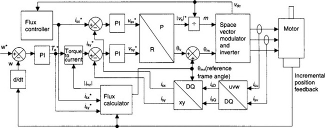
The following are some examples of applications where permanent magnet servo drives are used:
• Machine tools where precise and dynamic performance is required.
• Pick and place applications where the requirements are less precise, but where rapid movements are required.
• More recently permanent magnet motors with high numbers of poles (e.g. 32 poles) have been in low speed applications such as direct (gearless) drives for lifts.
19.4.2.4 Four-quadrant operation
A.c. voltage source inverter drives are normally based on the power circuit shown below in Figure 19.35(a). This power circuit has the following drawbacks:

Figure 19.35 Alternative a.c. drive power circuits: (a) standard a.c. drive power circuit; (b) four-quadrant drive power circuit
• Although the inverter allows power flow in either direction, the diode rectifier only allows power to flow from the supply into the drive. Therefore the chopper circuit must be used to dissipate unwanted energy in the resistor when braking power is fed from the motor to the drive.
• The currents taken from the supply generally contain significant harmonics.
• The voltage at the inverter input is theoretically limited to the peak line voltage of the supply. In practice this is reduced further by voltage drops in the converter. This limits the maximum output voltage without over-modulation to less than the supply voltage.
If the diode rectifier is replaced with an inverter as shown in Figure 19.35(b), the input currents can then be controlled to give almost sinusoidal waveforms with unity displacement factor. It is also possible for power to flow in either direction through the input inverter so that the drive gives full four-quadrant operation.
The input inverter can be controlled in a similar way to an inverter supplying a motor, using the reference frame based control system described in previous sections. A control system for the input inverter is shown in Figure 19.36.

Performance and applications: The performance characteristics of the four-quadrant drive described here can be summarised as:
• Full four-quadrant operation.
• Approximately unity displacement factor and minimal input current harmonics.
• Fast transient control of the d.c. voltage at the input to the motor inverter even during motor transient operation.
• The d.c. link voltage of a drive with an input diode rectifier is limited to less than the peak line supply voltage. With an input inverter the d.c. link voltage can be boosted to levels above this.
Four-quadrant drives are used in applications where good quality input waveforms are required and/or significant braking energy can be returned to the supply. The following are some examples of applications where this type of drive is used:
19.4.2.5 Direct torque control
The drive control systems described so far all use space vector modulation to produce the inverter control signals. An alternative method of control that can be used when a motor is connected to the drive is direct torque control.
An example of a control system based on direct torque control is shown in Figure 19.37. The torque reference, Te*, and the flux magnitude reference, |ϕs|*, are derived in the same way as for a drive using a space vector modulator. The hysteresis comparators then produce the required change in flux and torque, and the switching table selects the required inverter state to give a voltage vector that will change the flux and torque as required. The angle of the stator flux, αϕS, is used to determine which 60° sector the stator flux is in, as different areas of the switching table are used for different sectors.

The direct torque control system requires an estimate of the stator flux and the torque for the hysteresis comparators, and an estimate of rotor speed for the speed controller. These are derived from a model based estimator using the motor currents and an estimate of the motor voltages from the switching table state and the inverter d.c. input voltage, Vdc. It is important to note that although the principle of direct torque control appears simple and does not depend on estimates of motor parameters, the motor model used to derive the estimates of torque, flux and speed is complex and is heavily dependent on the motor parameters. The following list gives a comparison between direct torque control and a control system based on a space vector modulator:
• The calculations for the current controllers, reference frame translation and space vector modulator are more complex than the direct torque control hysteresis comparators and switching table. However the sample rate required for direct torque control (typically 40 kHz) is much higher than that for a space vector modulator (6–12 kHz), because direct torque control uses a hysteresis method.
• As well as supplying a single induction motor, most induction motor drives can also supply more than one motor in parallel where the motors are different sizes, or the drive can be used as a general purpose variable frequency/variable voltage power supply. Direct torque control cannot be used in these applications, and so a direct torque control drive must also be able to operate with space vector modulation for these applications.
• Because direct torque control is based on hysteresis controllers the inverter has a continuously variable switching frequency. This is considered to be an advantage in spreading the spectrum of the audible noise from the motor, but the range must be controlled so that it does not exceed the maximum allowed by the power electronics of the inverter. Care must also be taken with direct torque control to ensure that changes from one voltage vector to another more than 60° away do not occur repetitively as this can increase the stress on motor insulation. • A direct torque control drive inherently delivers a change in torque in the shortest possible time within the limits of the sample rate. Because of the sampling and calculation delays usually associated with space vector modulator based systems a change in torque can take several samples. However, deadbeat type algorithms can be used with a space vector modulator systems giving performance which compares well to that of direct torque control.
19.5 Applications and drive selection
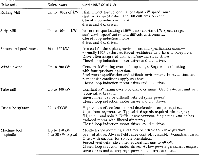


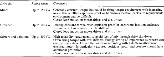
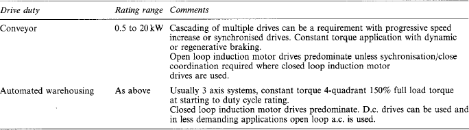


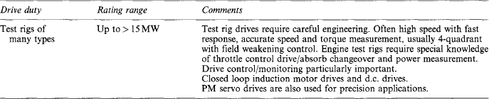


19.6 Electromagnetic compatibility
Electromagnetic compatibility of electrical drive system is a complex but vitally important subject. By their very nature by rapidly switching voltages and/or currents, drives can form very effective noise generators. The design of the drive must therefore be very carefully considered from the early stages firstly to ensure that the drives own controls are not interfered with and secondly that the drive can be applied in a system without adverse effects on other equipment.
Various national and international standards exist for EMC—few have been written with power electronic drives in mind. Drive manufacturers are now making great efforts to design drives compliant with the existing and future standards—they should be consulted for advice on appropriate standards and compliance thereto.
Bibliography and further reading
The documents listed here have been selected to provide the reader with useful sources of information and further reading relating to Electrical Variable Speed drives and their application.
1. A reference for fundamental power converter operations and relationships Moltgen, G. Converter Engineering. London: John Wiley; 1984. ISBN 0-471-90561-5
2. A practical reference book covering many aspects of characteristics, specification, design, selection, commissioning and maintenance Chalmers, B.J. Electric Motor Handbook. Butterworths; 1988. ISBN 0-408-00707-9
3. General background to the theory of vector control of motors Vas, P. Sensorless Vector and Direct Torque Control. Oxford University Press; 1998. ISBN 0-198-56465-1