
Installation
Regulations and specifications 38.2
Stand-by and emergency supplies 38.9
Low-voltage switchgear and protection 38.11
Moulded-case circuit-breakers 38.11.2
Miniature circuit-breakers 38.11.3
38.1 Layout
This chapter deals with the installation of a power supply to a consumer. One example might be a large industrial concern with a factory complex spreading over several hectares; another the single tower-block with one supply entry point in the basement but with additional substations at intermediate floors. At the other extreme is the small dwelling-house.
The general rules of safety of personnel and equipment, continuity of supply and ease of operation and maintenance apply to all consumers, but the layout naturally varies with the individual establishment.
38.1.1 System supply
When an electricity supply is to be provided to a factory or building complex, there are several features that must be taken into account. Safety is one that cannot be measured in terms of capital cost, but it should not be difficult to achieve an acceptable standard, provided that good-quality equipment is purchased, properly installed and well maintained, and operated by experienced staff.
Loss of supply may result in loss of output from factory or danger to life in a hospital. The system designer must take these matters into account. To eliminate all risk of outage is likely to be very costly: the alternative of accepting some measure of risk is often preferable, bearing in mind the present-day reliability of the public electricity supply and the equipment available for installation.
Losses occur in cables, overhead lines and transformers, and the system should be designed to minimise these, by locating substations as near as possible to the centres of the load. The system power factor is also relevant, for it can affect equipment sizing, I2R losses and the cost of electrical energy.
In few installations is maintenance afforded the importance it deserves. The design and installation engineer cannot control this, but he can ensure that the equipment supplied allows for proper isolation and regular testing with the minimum interruption of supply.
Few installations remain unchanged throughout their life. Whether it be the provision of a spare way on a distribution board or space for an additional high-voltage ring-main circuit, thought should be given to the problem at the time of design and installation.
In determining the cost of installation it must be borne in mind that, in addition to the capital cost of the equipment, attention must be given to the running cost, and also to the cost of providing accommodation for the equipment. For example, it may be better to provide outdoor equipment rather than less costly indoor plant when provision of a building to house it, is taken into consideration.
38.2 Regulations and specifications
In the UK, the supply of electricity to premises is governed by the Electricity Supply Regulations, which require that all electrical equipment in the premises shall be maintained in an efficient state and that, as regards high-voltage equipment, authorised persons are available to cut-off supply in emergency. Users must also be mindful of the Electricity at Work Regulations 1989 (EAW). These have extended the powers of the Health and Safety Executive to all places of work. They impose legal requirements on a wide range of personnel, with the object of insuring safe working practices in the use, operation and maintenance of electrical installations. The reader’s attention is particularly drawn to an associated document ‘Memorandum of Guidance’, which as its title suggests, provides extremely useful help in interpreting the EAW Regulations. It should be pointed out that the Health and Safety Executive regards compliance with the Institution of Electrical Engineers (IEE) Wiring Regulations [BS7671:1992 with amendments] (referred to in detail in the following paragraphs) as being likely to achieve compliance with the relevant aspects of the EAW Regulations, but it is also necessary to have safe operational and maintenance procedures for personnel working on, or near, electrical installations to ensure full compliance with the EAW Regulations.
The actual erection and installation should comply with the IEE Wiring Regulations—Requirements for Electrical Installations: compliance with these Regulations will produce a high standard of work and allow a good factor of safety against possible breakdown.
In 1981 the new edition (15th) of these Regulations (referred to as WR 15) marked a radical change in both style and approach. It is based on internationally agreed installation rules, the two bodies concerned being the International Electro-technical Commission (IEC) and the European Committee of Electro-technical Standardisation (CENELEC). This approach has now been carried a stage further with the introduction in May 1991 of the 16th edition of the Wiring Regulations (WR 16). The concept has been carried further with the 1992 updated edition of the 16th edition of the Wiring Regulations (WR 16) and the 2000 amendment no 3 available on the internet.
Every IEC Standard issued expresses, as nearly as possible, an international consensus on its subject, and the intention is that every member country should adopt the text of the standard, as far as the individual country’s conditions will permit. Additionally, the members of the EEC are committed to removing trade barriers, and CENELEC aims to help in this by attempting to ‘harmonise’ the corresponding national standards. In 1968 IEC started work to formulate standard rules. It was soon realised that combining the existing rules of member countries was not feasible, and so IEC decided to go back to fundamentals. Whilst the work continues, some sections have been published, and the IEE made use of the IEC plan and the technical content already agreed by IEC in revising the Wiring Regulations. This resulted in the 15th and 16th editions of the Wiring Regulations being very different from any previously published. Basically, they were aimed directly at the designer of electrical installations rather than at the site installer. They demanded an analytical, mathematical approach to the design of the installation. Additional design time is needed, but the designer is given a greater degree of freedom to produce an economic design.
In the latest edition (WR 16) there is no fundamental change in this approach, but harmonisation is taken a stage further, as can be seen from the list of CENELEC harmonisation documents in the Preface. The number of appendices has been greatly reduced, but in their place the IEE has published a series of guidance notes on specific subjects. Of particular relevance is the ‘On Site Guide’, which should prove invaluable for the installer who may not be totally familiar with every detail of the Wiring Regulations. By following the ‘On Site Guide’ in his work the installer can be assured that the installation will be acceptable, and safe in operation, although it may not be the most economical design possible.
Mention must also be made of two books sponsored by the Electrical Contractor’s Association, the Handbook on the 16th Edition of the IEE Regulations (which is also sponsored by the National Inspection Council for Electrical Installation Contracting) and Electrical Installation Calculations, the latter by B. D. Jenkins.
It must be pointed out that casual and occasional reference to the Wiring Regulations is not enough to inform readers of the requirements. This can only be achieved by study of the Regulations in detail.
Mention can be made of other regulations and specifications used in other parts of the world. In the former UK colonies earlier versions of the IEE Wiring Regulations have been adopted and modified to suit the engineering environment of the country, i.e. The Central African Standards (CAS Wiring Rules) are based on the earlier 13th and 14th IEE Wiring Regulations and are used in central Africa including Zimbabwe and Malawi.
In parts of the world where there is an American influence then the NFPA70 (National Electrical Code) is adopted.
The National Fire Protection Association has acted as sponsor of the National Electrical Code since 1911. The original Code document was developed in 1897 as a result of the united efforts of various insurance, electrical, architectural, and allied interests.
NFPA has an Electrical Section that provides particular opportunity for NFPA members interested in electrical safety to become better informed and to contribute to the development of the National Electrical Code and other NFPA electrical standards. Each of the Code-Making Panels and the Chairman of the Correlating Committee reported their recommendations to meetings of the Electrical Section at the 1995 NFPA Annual Meeting. The Electrical Section thus had opportunity to discuss and review the report of the National Electrical Code Committee prior to the adoption of this edition of the Code by the Association.
38.2.1 Purpose
Practical Safeguarding: The purpose of this Code is the practical safeguarding of persons and property from hazards arising from the use of electricity.
Adequacy: This Code contains provisions considered necessary for safety. Compliance therewith and proper maintenance will result in an installation essentially free from hazard but not necessarily efficient, convenient, or adequate for good service or future expansion of electrical use.
Hazards often occur because of overloading of wiring systems by methods or usage not in conformity with this Code. This occurs because initial wiring did not provide for increases in the use of electricity. An initial adequate installation and reasonable provisions for system changes will provide for future increases in the use of electricity.
38.2.2 Scope
1. Installations of electric conductors and equipment within or on public and private buildings or other structures, including mobile homes, recreational vehicles, and floating buildings; and other premises such as yards, carnival, parking, and other lots, and industrial substations.
For additional information concerning such installations in an industrial or multibuilding complex, see the National Electrical Safety Code, ANSI C2-1993.
2. Installations of conductors and equipment that connect to the supply of electricity.
3. Installations of other outside conductors and equipment on the premises.
4. Installations of optical fibre cable.
5. Installations in buildings used by the electric utility, such as office buildings, warehouses, garages, machine shops, and recreational buildings that are not an integral part of a generating plant, substation, or control centre.
38.3 High-voltage supplies
The general method of supplying bulk power to factories or other complexes is by means of an HV supply, usually at 11 kV, occasionally at 6.6 kV. The installation comprises a main substation at the point of entry, with HV cables to supply subsidiary substations located near load centres. Where desirable, it may be possible for the consumer to obtain two supplies from the power authority, and in special cases where loss of supply could give rise to a particular hazard (e.g. the danger to life in a hospital), the two supplies may be provided from separate sources. In buildings containing IT equipment requiring n + 1 reliability in power supplies then dependability calculations would be undertaken to determine the Reliability, Availability, Maintainability and Safety (RAMS) of the bulk power supply systems.
The distribution system generally comprises either radial feeders or a ring main using underground cables to supply the subsidiary substations. The emphasis today is towards ring-main supplies, and this is considerably helped by the ready availability of competitively priced ring-main switchgear. The basic unit comprises two switches, earlier installations used to be oil but SF6 has now taken over, capable of making on to a fault and of breaking load current, and a fuse switch. Other units are available, assembled into various configurations. They can include circuit-breakers. The SF6 insulated ring-main unit switching takes place in a SF6 pressurised compartment. This equipment has obvious advantages for indoor installation because of the reduced fire risk.
A SF6 ring-main unit is illustrated in Figure 38.1.

Four distribution arrangements are illustrated in Figure 38.2(a—d), although variants are also available.

Figure 38.2 Alternative supply system designs: (a) radial feeder; (b) simple ring main arrangement; (c) distribution substation with outgoing cables controlled by switch and fuses; (d) HV installation with automatic circuit-breakers
Figure 38.2(a) is a radial-feeder arrangement with each feeder controlled by its own automatic circuit breaker. A cable or transformer fault will result in loss of supply only to the one sub-station, but supply cannot be restored until the repair is effected.
Figure 38.2(b) is a simple ring-main arrangement which allows for any individual transformer substation to be isolated for inspection or test without interrupting the supply to the other substations. Any fault occurring on the system will result in a total shut down, but the fault can be isolated and the supply restored to all substations but one, unless the fault is in the cable between substations C and D, in which case all substations can be re-energised.
In Figure 38.2(c) the distribution substations have their outgoing cables controlled by switches and the transformer by a fuse switch. Hence, every transformer can be independently switched, and should a fault occur and one of the fuses blow, the fuse switch is arranged to open all three phases automatically, thus disconnecting the transformer from the system.
The system would normally be operated with the ring open, but any cable fault will result in part of the system being shut down until the fault is located, when power can be restored to all the substations.
By using automatic circuit-breakers throughout, as shown in Figure 38.2(d), a greater degree of security of supply is obtained. The system can be operated as a closed ring, and even greater security is obtained by duplicating the transformers as shown in the figure.
Modern transformers and switchgear are very reliable, and, provided that cables are installed carefully, the number of faults that will occur will be extremely small. Since cost will always be of importance, it is common to use the simplest ring-main switchgear configuration that is acceptable for the particular application, and switches with a fuse-switch tee-off represent very good value for money and are widely used both by public electricity authorities and by industry. The situation is helped by the availability of fault monitoring and locating equipment, usually of the earth fault passage indication variety. This comprises a core balance current transformer on the out-going feeder cable with an associated hand or self-reset relay. Remote tripping of the switch fuse is also available. With the advent of low-cost micro-processor equipment the system of fault location and monitoring has been extended to provide more exact information to identify the location of a fault.
38.4 Fault currents
A relatively simple calculation determines the required interrupting capacity of switchgear. This is particularly useful to the installation engineer when it is necessary to provide extensions to an existing system. He must ensure that any changes in fault currents are safely interrupted via the breaking capacity of 13.1 kA at 11 kV switchgear. Where old gear is already in use, problems could arise.
The technique involves using the reactances of the equipment. In the case of underground cables, the resistance is high compared with the reactance and so for calculation purposes the impedance of the cable is used. For generators the sub-transient reactance is used, as it is effective for the first few cycles following a fault.
The ratio between the phase voltage drop and the normal line-to-neutral voltage for a stated current (or kilovolt-amperes (kVA)) is the per-unit (or per cent) impedance at that current. For example, if a 1000 kVA transformer has a 0.05 p.u. (or 5%) reactance, then its voltage drop on rated load is 0.05 of the line-to-neutral voltage. It follows that if the transformer output terminals are short-circuited, the volt drop is 1.0 p.u. (100%) and the short circuit kVA loading is 1000 × (1/0.05) = 20 000 kVA, and this is the maximum that the transformer can pass. Again, consider a length of 11 kV cable of impedance 1 Ω/phase and carrying 1000 kVA. The current is ![]() , the phase voltage is
, the phase voltage is ![]() , the volt drop is v = 52.5 × 1.0 = 52.5 V, and the impedance of the cable is (52.5/6350) = 0.0083 p.u. (0.83%).
, the volt drop is v = 52.5 × 1.0 = 52.5 V, and the impedance of the cable is (52.5/6350) = 0.0083 p.u. (0.83%).
Calculation of the interrupting capacity S required at a point in a system is by assuming an arbitrary kVA/S0 in the system, and evaluating the voltage required to pass this load as a fraction x of the line-to-neutral voltage. Then S = S0/x. The effective reactance of the system configuration involves summing branches in series and parallel and, in some cases, the application of the star/delta transformation technique. The availability of computer software that enables engineers to undertake fault analyses, protection and regulation calculations now speeds up the calculation process. Table 38.1 gives typical values of reactance for generators and transformers.

38.5 Substations
The space requirements of a substation depend on the equipment to be housed, and on whether a new building can be erected for it or it has to be fitted into an existing building. In the latter case it may be difficult to achieve an ideal solution, but where no severe limitations are imposed the layout in Figure 38.3 would prove satisfactory. This is suitable for a main 11 kV substation, also supplying local l.v. distribution, and it will be seen that it meets most of the following requirements:

(1) There is adequate clearance around the equipment and space to withdraw circuit-breakers for maintenance.
(2) Equipment operating at different voltages is segregated (advisable but not mandatory).
(3) There is sufficient space for drawing in and connecting cables, and for the delivery and erection of additional switchgear: doorways are high and wide enough.
(4) The walls can act as fire barriers. If a h.v. bus-section switch is included, a decision must be made as to the need for fire barrier walls between the sections. Even with oil circuit-breakers, this risk is small and many engineers disregard it.
(5) Transformers are usually housed in open or semi-open compounds; but if an indoor location is essential, particular attention must be paid to its ventilation. The risk of a transformer fire is extremely small: nevertheless, an oil sump (usually filled with pebbles) should be provided to trap burning oil which could escape following a fire.
The substation design described above can be said to be traditional, but in recent years, with the almost universal use of vacuum and gas-insulated switchgear from 11 to 15 kV, and with the growth in availability of cast-resin distribution transformers, there has been a re-think on substation design for many applications. Over the past 20 years the concept of package substations was introduced whereby cast-resin transformers, low voltage switchgear, automatic power factor correction equipment and 11 kV switchgear is incorporated into a composite arrangement. It should be realised that there are savings in installation costs with possible improvements in safety as mentioned in 38.5.2. Today it is not unusual to find commercial buildings with electrical loads totalling tens of megawatts. The recent explosion of the IT industry and internet server installations has seen electrical loads in these bespoke buildings of up to 400 megawatts. The traditional approach of locating the transformers in the basement or in an outdoor compound with 415 V cabling to the l.v. switchboards may result in a very expensive distribution system. A new approach is to run 11 kV cables throughout the building to substations which incorporate the 11/0.415 kV transformer(s) as well as the 415 V switchgear. Typical of this is the combined board shown in Figure 38.4. In this illustration the transformer is of the dry insulated type, but increasingly cast-resin units are used. Both exhibit strong fire-resistance characteristics. This same approach can be as readily applied to industrial buildings.
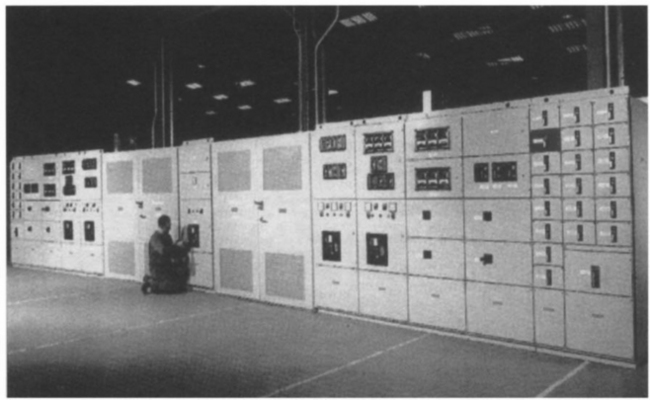
Figure 38.4 ABB 415 V switchboard, incorporating dry type 11/0.415 kV transformer, main incoming l.v. air circuit-breaker and outgoing l.v. circuits
To simplify the stock of spares and to ensure ready inter-changeability between gear in different substations, as much standard equipment as possible should be used, even at the expense of varying from the ideal installation. In general, substations should be limited to a capacity of about 2000 or 3000 kVA, with individual transformers no larger than 1500 kVA, to allow for the use of commercial l.v. switchgear of about 43 kA rupturing capacity.
38.5.1 Low-voltage equipment
At substations the l.v. distribution gear consist usually of a circuit-breaker for each transformer with circuit-breakers, or switches and fuses for the outgoing feeders. L.v. feeders are usually supplied with ammeters and often with meters to measure the energy consumption of the feeder. In many cases maximum-demand meters are included so that this feature can be periodically monitored—a useful facility in large industrial complexes. Intelligent l.v. switchgear is now available where strategically placed voltage sensors and circuit telemetry is monitored by a PLC. Thermal monitoring of bus-bars and connections using continuous infra-red detectors are also available.
Feeders radiate to the various sectional distribution centres, where they terminate at switchboards to which smaller sub-main cables are connected, supplying power to the various departments or shops by means of other small distribution boards. The most important feeders will again be duplicated or interconnected to some extent, to safeguard the supply, so that a l.v. breakdown will result only in a temporary shutdown of one section. With duplicate cables, one may be entirely spare or both cables may share the load, provided that they are both of sufficient capacity to carry the total current independently in emergency.
38.5.2 Packaged substations
In addition to the substation designs referred to in Section 38.5 the so-called ‘packaged substation’ has become increasingly popular. A typical design incorporates an h.v. SF6 switch, a cast resin transformer and fused l.v. outgoing ways. They are popular with supply authorities partly because of their compact construction, which makes them attractive for installation where space is at a premium. They also require the minimum of site erection work. They can be supplied complete with a prefabricated enclosure, often of moulded reinforced fibreglass construction, or unclad and suitable for direct installation in a building.
38.5.3 Low-voltage distribution
From the substations described earlier, l.v. feeders run to subsidiary substations or load centres. These can include multi-motor starter boards, air-conditioning control boards, lighting and heating power distribution boards, vertical or horizontal bus-bars, street lighting supplies, etc. The range of alternatives is wide and the following paragraphs outline only some of the solutions available.
Multi-motor starter boards: Large motors are usually supplied with independently separate feeders. Motor starter boards will probably have the facility for intelligent motor protection. This is advisable because of the heavy fluctuating load, which might otherwise cause disturbance to other plant on the same supply. However, where a number of small or medium sized motors are in reasonable proximity, it is convenient to group the starters in a multi-motor starter panel, which often includes one or more distribution boards for lighting.
Air conditioning and ventilation control boards: These are variants of the multi-motor starter board. As well as starters for the fans and pumps of the system, they also include the specialist control equipment needed for the automatic control of the air conditioning and ventilation. Similar developments are found in many industries where plant process control equipment is incorporated into combined motor starter and small-power boards. These starter boards may also incorporate equipment for Building Management systems and communications capability to connect onto circuit breakers and MCCBs which allows diagnostic data, indication signals and energy management to take place.
Intelligent motor control can be incorporated to monitor overload, overheating and earth faults.
Bus-bar systems: In general, wherever there are continuous rows of machine tools to be fed, an overhead bus-bar system provides the required degree of flexibility. Used vertically, a bus-bar system offers simple and flexible provision of power in a high-rise building. Several manufacturers market copper/aluminium bus-bars, embedded in epoxy cast resin, enclosed in steel trunking and provided with tapping points at intervals. Standard tees, bends and other accessories are available. At the tapping points it is possible to insert a tapping box, which can be safely applied or removed with the internal bus-bars live. When positions of machines have to be changed or new machines installed, it is easy to insert a tapping box at the appropriate point in the run of the busbar trunking. The maintenance cost is low, depreciation is minimal and there is a high recovery value if the trunking has to be demounted and rerun. Earth continuity can be provided by an external link bolted between lengths of trunking, but for large ratings a separate earth conductor is necessary. No cables other than the bus-bars themselves may be included within the trunking. Fire barriers are required for vertical runs, and for long runs it is advisable to provide bus-bar expansion joints.
From the individual fuse switch (or circuit-breaker) units on the overhead bus-bar, cables in conduit or flexible metallic tubing are run to the machine tools. In the case of tools with more than one motor, distribution boards can be mounted at a convenient point on the equipment.
Vertical bus-bars are usually run in a vertical duct within the building. A lock-proof cupboard is formed at each floor level and the distribution boards and switches are accommodated therein, with the outgoing supplies fed to meet the lighting and power needs of the floor occupants. Where possible, it is preferable to use only one phase on each floor of the building, as this eliminates risk of voltages in excess of 240 V being encountered by personnel.
38.6 Wiring systems
The choice of wiring system for industrial, commercial and domestic installations depends on the structure, application, supply voltage, load, appearance and cost. An essential feature is a proper earthing system giving an earth continuity conducting path for protection and safety.
38.6.1 Steel conduit
Screwed steel conduit, either galvanised for corrosion resistance or black enamel, provides a potentially good earth continuity, and makes it possible to enclose cables throughout their length with strong mechanical protection. The conduit is normally of a heavy-gauge welded construction.
Skill is required to achieve a proper system of good appearance. The conduit should be erected completely before cables are drawn in; tube ends should be reamered to prevent damage to cables; draw-in boxes should be amply proportioned and accessible; the conduit should be adequately supported by saddles or clips. There should be no more than two right-angle bends (or their equivalent) between successive draw-in boxes. The whole system should be mechanically continuous throughout, including connections to switches, fittings, distribution boards, motor control gear and the metal cases of other equipment; and it must be properly earthed.
Most conduit systems in factories are run on the surface, but in offices, or where conduit would be affected by corrosive fumes, it may be sunk in concrete in the floor or in walls behind plaster or cement. The layout must be carefully pre-planned, and joints must be tight, to prevent the ingress of wet concrete, cement or plaster. A draw wire should be pulled through as soon as possible after pouring or plastering, to remove any intrusive material before it hardens. The actual wiring is left until all is dry, and all wiring in one conduit must be drawn in at the same time.
38.6.2 Plastic conduit
In recent years there has been an upsurge in the use of plastic conduit. Polyvinyl chloride (PVC) components are generally unaffected by water, acids, oxidising agents, oils, aggressive soils, fungi and bacteria, and they can be buried in concrete or plaster. They provide slight resistance to heat and flame, and in this respect are inferior to steel conduit. Their mechanical strength is also much less.
Flexible heavy duty nylon conduit is also available for cable protection in installation systems. This system is self-extinguishing, free of phosphor, halogen and cadmium and is shock resistant.
They are not electrically conductive and separate earth continuity conductors have to be run, which on occasion can require a larger diameter than for a steel conduit. Expansion couplings may need to be included in long straight runs, as linear expansion of PVC gives it an extension of about 1.5 mm/m for a temperature rise of 20°C. On the other hand, the conduit can be readily cut by hacksaw and bent when gently heated. PVC conduit can be screwed using suitable dies, but jointing of lengths is commonly by a solvent welding compound. This is easier, quicker and provides an entirely watertight joint.
PVC conduit and fittings are marginally cheaper than the equivalent steel conduit components, but PVC is a by-product of the oil industry and its price comparison with steel conduit is likely to vary.
38.6.3 Trunking
Trunking is used to bunch numbers of cables or wires which follow the same route, with branches to motors, switchgear and lighting circuits by spurs in trunking or conduit. Trunking is made in various sections from 50 mm × 50 mm upward and in standard lengths. Tees, reducers, crossings, elbows and other fittings are made as shown in Figure 38.5.

Both steel and plastic trunking are used. With the former, low-resistance joints between lengths of trunking and fittings are essential. If the trunking is itself used as a ‘protective conductor’ under the requirements of the Wiring Regulation, its bonding and jointing are specified. Where conduits connect to the trunking, a clearance hole is drilled in the trunking wall and the conduit connected with a socket and male bush. Connections between trunking and switchboards and similar panels are generally effected by flanges securely bonded to the trunking and bolted to the switchgear.
On a switchboard or distribution panel in which lengths of trunking enclose the various interconnecting cables, the units should be bonded to the trunking by a copper earth tape. In the case of vertical runs of trunking, internal fire barriers must be fitted at each floor level. These barriers must also be fitted in horizontal runs where the trunking passes from one zone of fire protection to another.
Plastics trunking is made in sizes similar to those for steel trunking, small sizes being extruded and large ones formed from PVC laminated sheet. Common fittings are available, but as PVC is easily ‘formed’, special fittings can be ‘welded’ with the help of a hot-air welding gun. The characteristics of PVC trunking make it particularly suitable for fume-laden atmospheres, humid tropical conditions and salt-laden coastal air. The material has the physical characteristics mentioned in Section 38.6.2 and for the same reason requires a copper conductor to be included to provide an effective earth. Screwed or snap covers may be used.
38.6.4 Cabling
Details of insulated cables or conductors are given in Chapter 31. The following cables have applications special to the wiring of buildings:
38.6.4.1 Mineral insulated metal sheathed cables
A mineral insulated metal sheathed (MIMS) cable normally consists of high-conductivity single-strand copper conductors inside a seamless copper sheath packed with magnesium oxide powder as the insulant. As an alternative aluminium conductors and sheath are also available. The sheath acts as a robust and malleable conduit, capable of withstanding considerable mechanical abuse. It is strongly fire resistant, and when covered overall with an LSF sheathing can withstand chemical corrosion.
Because magnesium oxide is hygroscopic, the exposed cable ends must be sealed. The sealants are suitable for operating temperatures up to 70°C, but special oil-resistant and high-temperature seals are available for special applications.
Although dearer than the equivalent steel conduit installation, there are applications where MIMS cabling is superior and preferred. For example, some fire authorities insist on MIMS cables for all fire protection, detection and alarm circuits.
38.6.4.2 PVC/PVC sheathed cables
For domestic installations, PVC insulated and sheathed cables are often used, run on the surface, or more usually buried in plaster. Since there is at least a perceived danger of buried cables being penetrated by a nail or screw driven into the wall, the IEE Regulations have since 1987 been amended to lay down strict rules as to the positioning of buried cables. For example, cable connected to any point or accessory on the wall must be run horizontally or vertically to the point or accessory; in this regard, the consumer unit is treated as an accessory.
In small industrial installations where cost is a prime consideration, it may sometimes be acceptable to run PVC sheathed cabling fixed by cleats spaced about 1 m apart. Cables should preferably not be concealed and must be protected where they run through floors, and also on walls if fixed at a level below about 1.6 m from the floor.
38.7 Lighting and small power
Whatever type of electrical installation is involved—be it for a factory, a public or commercial building, or domestic premises—supplies for electric lighting and small power will be needed.
38.7.1 Lighting circuits
There are two main ways of running lighting circuits, ‘loop-in’ and ‘junction box’. Both can be used in the same installation. In the loop-in system (a) in Figure 38.6 the terminals for joining the cable ends form part of the ceiling rose. The junction-box system (b) is used when the lighting fittings have no loop-in terminals, or to save cable when the lamp and the switch are far apart. The connections are similar to those in the loop-in system. The new 3 and 4 pin plug in lighting system now offers the installer greater flexibility and ease of installation especially with dimmable fluorescent lighting and emergency lighting circuits.

Figure 38.6 Ceiling rose loop-in and junction-box wiring: (a) loop-in system; (b) junction-box system. — Red. always live; —, black, neutral except where returning from a switch; —, earth; —.—.—., flex to lamp
38.7.1.1 Two-way switching
The two-way switch is a single-pole changeover switch. When interconnected in pairs, two-way switches provide control from two positions and are therefore installed on landings and staircases, in long halls and in any room with two doors. The arrangement is as shown diagrammatically in Figure 38.7(a).

38.7.1.2 Intermediate switches
Where there are long halls, corridors or passageways, with several doors, it may be convenient to introduce additional switching positions. The ‘intermediate’ switch enables any number of additional switching points to be introduced to the two-way switch circuit, as in Figure 38.7(b).
38.7.1.3 Master control switching
A master control switch is sometimes provided to give overall control to a number of lamps which are, in addition, independently switched, as in Figure 38.7(c). A typical installation would be an hotel bedroom or suite, where a double-pole switch at the entrance to the room will switch off all lights on the occupants leaving the room.
In new office installations, increasing use is being made of master control switching, usually by way of sophisticated relay systems which allow groups of lights (sometimes whole floors) to be controlled by timer, or by measuring the ambient light conditions and switching lights ‘off’ or ‘on’ to suit.
More modern lighting controls will consist of internal and external illumination sensors connected to microprocessor controls which monitor and control luminaires, from the window line, to achieve energy savings and sophisticated lighting control via high frequency dimming for T5 fluorescent lamps.
The new generation of micro-processor based control units incorporate LCD touch panels to enable activation of pre-set lighting schemes together with adjustment of blinds, air conditioning and sound systems.
38.7.2 Small power circuits
The socket outlet is a safe and convenient means by which free-standing or portable apparatus can be connected to an electric supply. It is false economy to limit the number of socket outlets installed. Sufficient should be provided to match the predicted needs of the consumer, and should be located adjacent to the most convenient point of use of the apparatus.
Both radial and ring final sub-circuits may be used to connect socket outlets, although in the UK the 30 A ring-main system using BS 1363:1984 fused plugs has held sway for many years. With this system, the current-carrying and earth-continuity conductors are in the form of loops, both ends of which are connected to a single way in the distribution board. The conductors pass unbroken through socket outlets or junction boxes (or must be joined in an approved manner). The ring may feed an unlimited number of socket outlets or fixed appliances but the floor area covered shall not exceed 100 m2. In domestic premises particular consideration should be given to the loading in the kitchen, which may require an additional circuit.
In the UK an unlimited number of fused connection units may be installed in a ring circuit, but the number of now-fused connection units must not exceed the number of socket outlets, or one permanently connected item of equipment. A typical ring circuit is shown in Figure 38.8.

Portable apparatus is now normally supplied with moulded plugs. At the same time more and more consumer units are being equipped with miniature circuit-breakers in place of fuses. It is also obvious that 13 A socket outlets to BS 1363; 1984: Pt 1:1995 are bigger, more obtrusive and more expensive than the Continental or American counterparts. Is it perhaps not time that we give some thought in the UK to a reversion to radial circuits and to non-fused plugs?
38.8 Floor trunking
Floor trunking is used mainly as a flexible means of providing small-power and telephone facilities throughout an open floor area. The basic methods are underfloor, open-top and cavity-floor systems. All must have continuity between metal sections and be adequately earthed.
38.8.1 Underfloor trunking
The several proprietary brands available consist basically of a closed trunking with one, two or three compartments, laid in a grid pattern on the floor slab. Specially designed intersection boxes take care of the crossovers in the lines of trunking, and fixed outlet boxes from the trunking are installed to meet all possible future needs. When the trunking is screeded over, the intersection and outlet box lids are flush with the final floor level.
38.8.2 Open-top trunking
Open-top trunking is a more recent concept of floor trunking. As with the underfloor trunking it is laid on the floor slab before screeding, but in this case the heavy-duty cover plates of the trunking are flush with the final floor finish, which makes it easy for outlet boxes to be added anywhere along the length of the trunking as changing needs demand, hence giving a greater degree of flexibility.
38.8.3 Cavity-floor systems/dado trunking
This flexible system comprises wood or metal square plates resting on support jacks. The services are run in conduit or trunking on the surface of the floor slab under the floor plates. Flush surface boxes can be installed into holes cut almost anywhere in the suspended floor, and wiring to power and telephone outlets is routed via conduits or trunking to central junction boxes. (A typical installation is shown in Figure 38.9.) There are now slim shallow products on the market with desk modules to connect to user power, voice and data appliances. Underfloor power distribution, available in 63 A, 40 A and 25 A is suitable for power to PC circuits and is available with clean and standard earthing systems.

Dado wall mounted cable management trunking consists of a series of single, twin and multi-compartment systems in various sizes produced in high impact UPVC. The trunking will accept wiring accessories and a bus-bar variant. The cable compartments are designed for power, communications and data outlets.
Data tray cable basket systems are manufactured from 50 mm × 50 mm wire mesh grid with the facility to provide take off or support positions throughout the length of the installation. The installed matrix system is ideal for most power, data, low voltage signal and some pneumatic systems.
38.9 Stand-by and emergency supplies
Provision for supply failure has sometimes to be considered, most commonly for emergency lighting in the form of (i) escape lighting (to ensure the provision of adequate illumination of emergency escape routes), and (ii) stand-by lighting (to enable normal activities to continue during the period of mains failure). The two most common systems of emergency lighting are: maintained, where normal lighting is fully maintained by automatic switching to an alternative source should mains failure occur; and non-maintained, where the emergency lamps are energised only when the normal lighting has failed.
Both systems are used extensively. The maintained system is essential in certain public buildings, and is the system preferred for ‘stand-by’ lighting.
Standards of emergency lighting are derived from the Fire Precautions Act 1971 and Fire Precautions Regulations Updates 1997. The CIBSE Lighting Code and BS 5266: Part 1 7:1999 also provides some useful guidance.
In the past, most emergency lighting systems were supplied from a central battery and charger unit, but self-contained emergency lighting luminaires have become readily available for both maintained and non-maintained systems. Each unit comprises a lamp, battery, charger and control equipment, and is wired conventionally into the normal lighting system. Usually a neon or diode indicator is incorporated to provide a visual indication that the battery is under charge. In general, where fewer than 20 fittings are involved, the self-contained luminaires are likely to give the more cost-effective solution. To be effective it is essential that emergency lighting is regularly tested and a maintenance procedure set in place. This can be done by semi-automatic and fully automatic testing.
38.10 Special buildings
With large high-rise buildings, the heavy electrical and mechanical services plant is usually located in the basement and/or basement and part-way up the building. However, there are occasions when air-conditioning chillers, stand-by generating plant and even boilers are located on the roof, and this can influence the positioning of the main electrical switchboards. Nevertheless, since the main power supply enters at basement level, it is usual to locate the main transformer and the primary substation in the basement. Basement-mounted equipment will normally provide supply for 10–12 floors, for taller buildings additional substations are required every 10–15 floors.
When equipment is installed in buildings to be used as offices or apartments, particular attention must be given to preventing unnecessary vibration. Rotating plant should be provided with anti-vibration mountings. In a new building the architect and the structural engineer should co-operate in providing a ‘floating’ floor to support equipment liable to vibration.
38.10.2 Public buildings
In installations for large buildings and special establishments open to the public (such as theatres, cinemas, etc.) special precautions must be taken in the layout of the electrical equipment. National standards and any regulations formed by the local authorities must be strictly observed in planning the scheme. These deal more especially with the requirements necessary to avoid danger to the public from fire, explosion, electric shock, etc. and are also concerned with the question of dual supply or emergency lighting in the event of a breakdown of the power mains.
38.10.3 Domestic premises
Domestic premises are commonly connected to the street supply by a one-phase l.v. PVC cable, often with aluminium conductors. The incoming supply is rated at between 60 and 100 A and is capable of supplying the lighting, heating and cooking demands of the house or flat.
The incoming cable terminates in a service cut-out and connects via the house meter to a consumer’s unit. There is an increasing desire with new housing to locate the meter in a position where the meter reader can read it without access to the house. The consumer unit is equipped with an incoming supply switch and outgoing ways using high rupturing capacity (HRC) fuses or miniature circuit-breakers. One or more 30 A ring mains for socket outlets will be provided. Immersion heaters fitted to hot-water cylinders in excess of 15 litre capacity should be supplied from an independent circuit. Electric cookers are fed by a final sub-circuit through a cooker control unit which may also include a 13 A socket outlet.
When the ratings of the protective devices or the quality of the earthing is such that an earth fault would not be cleared within the prescribed time, a residual-current device (r.c.d) should be fitted. It could cover a whole domestic installation, but there can then be a risk of spurious tripping caused by the normal leakage currents of healthy equipment.
An alternative would be to use one r.c.d on a socket outlet circuit. Certainly, if a socket outlet is used to connect garden tools, this should be protected by an r.c.d. The r.c.d can be incorporated in the consumer unit; a unit comprising one socket outlet and an r.c.d unit can be contained in a twin-socket box or a plug in unit.
38.11 Low-voltage switchgear and protection
Heavy switchgear is dealt with in Chapter 34. The term ‘industrial switchgear’ is generally applied to that used for voltages not exceeding 600 V and controlling power from the l.v. side of a transformer to distribution boards which may include automatic circuit-breakers, or to fuse switches and contactors for motor-starting equipment. Consideration must be given to the prospective fault current at the point of installation, particularly as it may directly affect personnel, often unskilled and unaware of the danger should the apparatus fail to perform its function.
Today oil circuit-breakers are out of favour for operation at 415 V. Air circuit-breakers are still preferred by many engineers to moulded-case circuit-breakers, and for the higher current and fault levels they are essential.
38.11.1 Air circuit-breakers
For the larger industrial and commercial consumer the principal switchboard, and often subsidiary switchboards, will normally comprise a factory built cubicle assembly, incorporating conventional air circuit-breakers with ratings up to 4000 A. Air circuit-breakers now normally incorporate microprocessor electronic protection and management controls. Composite boards with a mix of air circuit-breakers, moulded-case breakers, fuse switches and contactor gear are also common. Segregation of components are via various forms of separation for the bus-bars, functional units and incoming or outgoing terminations. The forms of separation range from Form 1 to Form 4b, type 7.
38.11.1.1 Forms of internal separation


Where the switchboard manufacturer is not also the manufacturer of the air circuit-breakers, the customer should seriously consider the use of ‘cassette’ breakers. With this design each breaker is delivered to the switchboard builder complete in a sturdy ‘box’, i.e. the cassette. The breaker design will have been type tested in its cassette. Hence the user can be satisfied that the breaker will retain its certified test rating when fitted in a custom-built switchboard. This cannot be assumed with breakers offered to the switchboard builder in ‘open cradle’ form. At the same time, the switchboard builder can be absolved from having to carry out separate type tests to guarantee the requisite ASTA rating.
38.11.2 Moulded-case circuit-breakers
Of particular interest to the installation engineer are moulded-case breakers which find wide use in commercial and industrial applications. They are primarily intended for applications such as protecting main feeder cables, or acting as main circuit-breakers controlling large banks of other circuit-breakers. As such, their major function is to provide back-up protection to the sub-circuit protective devices. Overcurrent protection is a relatively secondary function. The moulded-case breaker is of more robust construction than the miniature circuit-breaker and can often be provided with auxiliary items such as extended operating handles for assembly in multi-switch cubicles, mechanical interlocking with adjacent breakers, motor-operated mechanisms and shunt trip coils. Current ratings up to 1250 A and short-circuit capacities between 25 kA to 150 kA are readily available.
38.11.3 Miniature circuit-breakers
Miniature circuit-breakers usually embody both overload and short-circuit current tripping devices, the overload usually by a thermal device, the short circuit by a magnetic one. A trip-free mechanism is incorporated so that the contacts cannot be held closed against a fault, and the thermal element prevents continuous rapid reclosing of a circuit when a fault persists.
The primary function of a miniature circuit-breaker is to protect an installation or appliance against sustained overloading and short-circuit faults, but it will also give protection against earth faults provided that the earth fault loop impedance is low enough. As a secondary function the miniature circuit-breaker can be used as an isolating switch or for local control switching. Today they are widely used in place of fuses in domestic installations where householders find them more convenient.
A circuit-breaker used to protect a sub-circuit should have a current rating matched to its load. The circuit-breaker rating must not exceed that of the cable; also, the current causing effective operation of the breaker must not exceed 1.45 times the lowest current-carrying capacity of any of the conductors in the circuit. (This requirement of WR16 also applies to other protective devices such as fuses.)
Miniature circuit-breakers are available with current ratings from about 0.5 to 100 A, with a fault capacity of 16 kA although values of 9/10 kA are more normal.
38.11.4 Fuses
The first edition of the IEE Wiring Regulations in 1881 contained a note reading: ‘The fuse is the very essence of safety’. Today, over 120 years later, fuses have to face competition from other devices, but in their many modern guises, though very different from their counterparts of the 19th century, they still play an outstanding role in the protection of electrical circuits.
The HRC fuse is the common type for general power system use. It was first introduced in the 1920s, and in the intervening years its design and performance have steadily improved, until today it has an unrivalled reputation as a short-circuit protective device. Its breaking capacity and energy and current-limiting ability are superior to those of any other protective device.
The design of the HRC fuse is described in Section 34.2.2.2. The most important design feature is the fusible link, usually of silver or silver/tin alloy, but often with the addition of other metal inserts. This enables the designer to achieve the desired time/current and other characteristics, striking a balance between conflicting requirements of minimum fusing current, low let through I2t and peak current on short circuit.
BS 88 was revised and up-dated in 1988, and is now identical to IEC 269 and BS EN 60269:1:1999, ‘Low voltage fuses’. It makes significant progress in the international standardisation of LV fuses. The aim has been to achieve safe electrical installations, particularly from the viewpoint of avoidance of electrical shock, both in normal and fault conditions, and the provision of overcurrent protection to the electrical cables forming the fixed installation.
Some of the fuse link types used in some European countries have only partial range breaking capacity, i.e. they interrupt short-circuit fault currents, but are unable to interrupt overload currents safely. To distinguish these types from the much more widely used general-purpose fuse links, the concept of ‘utilisation category’ has been introduced in IEC 269, and in the revised BS 88:1988.
Each of the classes is identified by a two-letter code. The first letter indicates the breaking range of the fuse link:
The second letter indicates the utilisation category:
The standards combine these letters to recognise three classes: i.e. gG, gM and aM.
Although harmonisation of the fuse dimensions as between the German, French, British and other systems has not yet been achieved, effectively there has been wide agreement on electrical parameters. This is a major achievement because it means that all general-purpose fuses, from whatever source, can be applied in the same manner. For example, for all fuses above 16 A rating, the fusing current shall not be less than 1.25In, where In is the fuse rating.
Similarly, compliance with the specification results in a discrimination ratio between major and minor fuses of 1.6:1 based on pre-arcing characteristics. When fault current in an a.c. circuit starts to rise, the fuse element heats and begins to melt. This takes a finite pre-arcing time. As the element ruptures arcing occurs and shortly afterwards the break is complete, the arcing ceases and the current drops to zero. This is the arcing time. The sum of these two is the total operating time. In the past it was accepted that discrimination between major and minor fuses should be based on the vast majority of installation, under fault conditions with total operating times, but it is now argued that in modern fuses the arcing I2t can be ignored. Even in three-phase circuits with relatively high power factors and fault levels up to 80 kA at 415 V, the 1.6:1 ratio is found to be valid, and this clearly provides economic benefits in any modern installation.
38.11.5 Prospective fault current
The prospective fault current at any point in a system is the current that would flow if there were a solid short-circuit at that point, and it represents the maximum current the protective device would have to interrupt. In practice, the actual current is usually much less than the prospective fault current because seldom does a solid three-phase short-circuit occur at the terminals of the protection device, and even short lengths of intervening cable reduce the fault current considerably. Nevertheless, knowledge of prospective fault current is necessary to ensure that the circuit-breakers, fuses, etc. in the system can deal with the fault current. If the fault level at the point is in excess of the rupturing capacity of the device, damage can be done to the installation and to the protective device itself, because of the amount of energy that passes before the current is completely interrupted. In such cases the protective device must be backed up by another breaker, or by fuses capable of interrupting the fault and before the ‘let-through’ energy has built up. The total ‘let-through’ energy is identified by I2t, where I is the fault current and t is the time for which the current flows before complete interruption.
38.11.6 Discrimination
A major consideration in designing a distribution system is the problem of ensuring effective discrimination. Ideally, the protective devices should be so graded that, when a fault occurs, only the device nearest the fault operates. The other devices should remain intact and continue supplying the healthy circuits. It is usually possible to assess, with fair accuracy, how effective the discrimination will be between combinations of circuit-breakers and fuses, but there are several practical considerations to be taken into account: (i) manufacturing tolerances in components, and (ii) operating conditions such that the devices do not conform to the published data. Over a period of time a fuse may be subjected to high currents causing it to ‘age’, and this can have an adverse effect on its behaviour.
In any medium to large installation, the supply is subdivided for distribution, and hence there will be protective devices (sometimes several) between the final device and its source of supply. At the other end of the scale, as in a domestic ring circuit, there may be fuses further down the line backed by miniature circuit breakers. The primary objective is to ensure that the device in question will deal with faults up to its breaking capacity, the back up device taking over above this level. (These other protective devices may be circuit-breakers or fuses.) This, theoretically, is the ideal condition, but in practice—to allow for the discrepancies mentioned above—it is usually advisable to aim for back-up protection taking over at a fault-current level not exceeding about 70% of the circuit-breaker breaking capacity. The need to comply with this requirement will automatically set the upper limit to the current rating of the back-up device. The lower limit of current rating is usually set by the need to avoid loss of discrimination.
Where miniature circuit-breakers in sub-circuit distribution boards are concerned, the miniature circuit-breaker should be the device to operate for all fault levels up to 1000 A, i.e. the great majority of sub-circuit fault currents. If the zone in which the back-up fuse tends to take over from the circuit-breaker is below 1000 A, discrimination troubles may be experienced, but provided that it is not below about 700–800 A, operating experience indicates that little trouble will be met on this score. If the zone is above 1300 A, the installation should be relatively free, in practice, from any form of discrimination trouble.
If fuse time/current characteristics are available, the probable position of the take-over zone can be addressed quite readily. The total time taken by a miniature circuit-breaker to clear a short-circuit fault is usually about 10 ms. If, therefore, the prearcing or melting time of the back-up fuse—at a given level of fault current—is less than 10 ms, it is reasonable to assume that at that level of fault current a m.c.b. will not consistently discriminate against the backup fuse. Thus, the current at which the fuse prearcing time/current characteristic crosses the 10 ms line will give a working guide to the position of the take-over zone.
The family of time/current characteristics shown in Figure 38.10 is for a typical range of quick-acting HRC fuses. From this diagram it will be seen that the 63 A characteristic crosses the 10 ms line at about 1000 A. From this it is reasonable to assume that the take-over zone, i.e. the range of current over which there is a possibility of loss of discrimination, will probably extend from about 800 to 1000 A. For fault currents less than 800 A there should be no trouble with the back-up fuse. With an 80 A fuse the zone will probably extend from about 1100 to 2500 A. Hence, if a quick-acting HRC fuse is used for back-up, ideally it should not be rated at less than 80 A, and preferably at not less than 100 A.
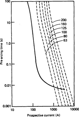
Figure 38.10 Time/current characteristics for HRC fuses and MCSs. HRC fuses —; HRC fuse; 30 A MCBs —
The use of readily available computer programs to undertake a full discrimination study would enable the engineer to add, select, change and delete a device with reference to fault levels, in rush conditions and measuring the grading margin.
38.11.7 Motor control gear
A motor starter may be an individual item of equipment, or one of several in a multi-motor starter panel. In general, the supply authority lays down the limits of starting current permissible. Small motors are normally switched direct-online, but larger machines may require starting methods that limit the starting current and power factor.
38.11.7.1 Isolating switches
The Electricity at Work Regulations and the IEE Regulations WR16 require that every motor be provided with a means of disconnecting the motor and all its auxiliary equipment, including any automatic circuit-breaker. The isolating switch should be mounted nearby and is often incorporated in the same case as the starter itself. The switch must be capable of making and breaking the stalled current of the motor and under normal conditions it remains closed. The switch often incorporates auxiliary contacts which (among other functions) isolate the control circuitry in the starter, to ensure that the starter and its control circuit are isolated before the door is opened and maintenance work begun. The regulations do allow an isolating device to be located remote from the motor, but under these circumstances provision must be made so that the means of isolation can be secured in the open position.
38.11.7.2 Contactor starter
For the smallest motors, a manual mechanical switch is acceptable; however, the Regulations require that means must be provided to prevent automatic restarting after stoppage (due to drop in voltage or failure of supply) where unexpected restarting might cause danger. Where such a device is provided, it is logical that it should also be used to operate the switching contacts, and this is the reason for the popularity of electromagnetically operated contactor starters. Many other advantages, such as easy control by relays, limit switches and other light current devices, follow the adoption of contactor starters.
There are two basic types of contactor—the electrically held-in and the latched-in type. With both, the contactor should close when the voltage is as low as 85% of nominal. With the electrically held-in type, should there be a transient failure of the supply, the contactor will drop out. With certain types of drive this can be embarrassing, and a latched-in contactor may be preferred. With this type, the ‘close’ coil energises the contactor, which then latches in, and the ‘close’ coil is de-energised. The contactor is opened by energising an ‘open’ coil or by the operation of a protective device.
38.11.7.3 Motor protection
Motor starters are usually fitted with a trip device which deals with overcurrents from just above normal running current of the motor to the stall current. The aim should be for the device to match the characteristics of the motor so that full advantage may be taken of any overload capacity. Equally, the trip device must open the starter contactor before there is any danger of permanent damage to the motor.
Contactors are not normally designed to cope with the clearance of short-circuit conditions, and it is therefore usual for the contactor to be backed up by HRC fuses or by circuit-breaker.
The arrival on the scene of very compact motor starters and the need to provide proper back-up protection to them has posed a problem. BS EN 60947-4-1 (1992) (previously BS 4941) ‘Motor starters’, describes three types of co-ordination, the most onerous condition (type C) requiring that under fault conditions there shall be no damage to the starter or to the overload relay. The usual back-up device will be the HRC fuse. It is important that the user check with the manufacturer’s catalogue to ensure that the correct fuse is used to secure this co-ordination.
38.11.7.4 Remote control of motors
When the starter is mounted remote from its motor, care must be taken in positioning the control push-buttons. Accidents can occur when the operator cannot view the motor from the control position; it may then be necessary to mount pilot lights adjacent to the motor to indicate to local personnel that it is about to start. In some cases, particularly with large complex machines, it may be necessary to give audible warning that the equipment is about to be started.
When an emergency stop button is located adjacent to the motor, it should be of the lock-off variety, so that when operated, not only does the motor come to a standstill, but also it cannot restart until the lock-off push-button has been released.
38.11.7.5 Braking and stopping machines
When it is necessary to stop a machine very quickly, some form of braking must be employed. An ordinary friction brake, the simplest device, should be held off against a spring or counterweight, so that it is applied automatically if power should fail. Electrodynamic braking is ineffective at slow speeds: it is therefore a useful addition rather than an alternative to a friction brake. Torque reversal (plugging) is very effective, but in many cases a reverse rotation cut-out will be required.
Care must be taken with the connection to the brake. Some motors tend to generate during run-down, and the brake circuit must therefore be interrupted positively to ensure that the friction brake is applied. A particular danger arises when rectified current is used for the brake solenoid on large machines. It may be found that the rectifier acts as a low-resistance shunt across the brake coil and prevents the magnetic flux collapsing quickly, making the brake action sluggish. In this case it is necessary for the main contactor to have separate contacts in the brake-magnet circuit.
When heavy machines are controlled by plugging, a problem will arise if the power supply should fail, for this would leave the machine uncontrolled, unless there is back-up emergency braking.
38.11.7.6 Limit switches
Limit switches are generally used to initiate a control sequence at the correct point in the mechanical duty cycle of a machine. For example, they may signify the end of a crane travel and initiate the stop sequence. Limit switches must be of robust construction—well protected against the ingress of fluids, dust or dirt. They are frequently used on machines expected to have a long life, and it is essential that the limit switches be equally generously designed. The current-carrying capacity of the electrical contacts should also be generously rated, since they may well have to handle in-rush current.
38.11.7.7 Inching control
When frequent inching is required, it is preferable that a separate contactor be employed. However, the motor circuit should still be taken through the overload protection device, to ensure that the motor is not allowed to overheat. At the same time the use of the separate contactor does restrict wear on the contacts of the main contactor.
38.12 Transformers
Most transformers used in industrial and commercial applications are either oil-filled or dry cast resin, natural-cooled and suited for mounting out of doors. The transformer is contained in a tank, plain or with cooling tubes or fins. Tanks may be equipped with small wheels, but more usually have a flat bottom for mounting on a concrete plinth. The modern transformer is reliable and tolerant of its location. In oil filled transformers, fires are infrequent but there is still some reservation with regard to siting oil-filled units indoors.
For such locations transformers with the mineral oil replaced by a non-toxic, biodegradable dielectric fluid, such as MIDEL, may be used. The use of polychlorinated biphenyls (PCBs) (Askerels) is now totally banned because of their toxicity an their perceived carcinogenic nature.
With the increasing need for transformers to be located indoors there has been a growth in demand for dry-type units, initially these were what used to be called class C type: i.e. with windings vacuum impregnated with silicone varnish, and with insulation and varnish selected to avoid the propagation of fire, and the emission of smoke and toxic fumes.
More recently, the demand has been for cast-resin transformers where each phase of the winding is encapsulated in epoxy resin. These units are usually supplied in ventilated sheet steel enclosures with lift-off access panels or lockable cubicle doors. Where access to a site is particularly difficult, these transformers can be dismantled before delivery and reassembled in situ, but obviously this is not a favoured activity.
As an optional item axial flow fans can be supplied to boost the output of the cast resin transformer by up to 25%. This feature can be useful, particularly where one of two units operating in parallel has to be taken out of service for maintenance. The boosted output of the remaining unit enables it to take up the additional load, probably without affecting the total load normally being supplied from the two units. Using the fans for regular day-to-day use is not recommended.
Whatever type is supplied, and wherever located, heat loss from a transformer makes ventilation important. Even at an efficiency of 99% there can still be many kilowatts of heat to be dissipated in a confined space!
It is usual for a transformer to be delivered ready for service, and it is recommended that the installation engineer does not remove the lid unless there is evidence of some abnormality. If, however, there is doubt, the check testing below is carried out.
(1) Voltage ratio—apply a low-voltage three-phase supply to the h.v. winding and measure the l.v. output voltage.
(2) Phase grouping—connect one pole of the h.v. and l.v. windings together (Figure 38.11): then by applying a three-phase l.v. supply to the h.v. windings, voltages can be measured and the grouping determined from the results.

It will be readily seen that in both the above tests it is imperative that the test l.v. supply be connected to the h.v. winding.
It is seldom that a small or medium-sized transformer is shipped without oil; but if this should happen, or if the transformer has been in store, it may be necessary to dry out the windings before commissioning the unit. If carried out at the manufacturer’s works, this would be done in a drying chamber, but on site it should be done by circulating currents in the transformer windings. It is then preferable that the oil be circulated through a filter plant at the same time. During the drying-out test, regular readings of the insulation resistance of the winding should be taken and checks made on the electric strength of the oil. The drying-out process is likely to take several days.
Where large transformers are concerned (say above 10 MVA), it would be foolish to proceed with any precommissioning or commissioning tests without enlisting the aid of the manufacturers.
38.12.1 Installation
Before connecting the transformer to the supply, several precautions are necessary. First, the tank should be efficiently earthed. In the case of a transformer with off-load taps, the correct tappings should be chosen.
With self-cooled units fitted with radiators, the valves at the top and bottom of the headers should be open. In the case of artificially cooled units, all the valves must be open and the correct quantities of oil and water should be circulating. Where the transformer is of the type employing forced oil circulation with a water-cooled cooler, the pressure of oil in the cooler must be greater than that of the water, so that, if there is any leakage, water will not be forced into the oil. In the case of transformers with fan coolers, these should be checked and tested, and the setting for the cutting-in of the fan checked.
Breathers, where used, should be fully charged with the drying agent. The jointing of the cable boxes should be checked, and where the transformer is fitted with bushings, these should be examined for cracks or chips, and if fitted with arcing horns, the gaps should be checked and set.
If the transformer is required to operate in parallel with another unit, it should be ‘phased in’, i.e. the phase sequence on the secondary, with the primary excited, should be identical with that of the other unit before the secondary is connected to the common outgoing supply. In a number of three-phase transformer connections there is a phase displacement of the secondary line voltage, as for example in a delta/star connected transformer. If the primaries of this be paralleled with the primaries of a star/star transformer, then it is not possible to run the secondaries in parallel, for the line voltages in the two cases have a phase displacement of 30°. A delta/star group may be paralleled with a star/delta or a star/interconnected star group, but not with a star/star or delta/delta group. A grouping commonly found in industrial and commercial work is the delta/star, either a Dy 1 or a Dy 11. In normal circumstances it is not possible to parallel Dy 1 and Dy 11 transformers, since, when the primaries are connected to the h.v. supply, there would be a 60° phase displacement between the l.v. connections. However, this can be corrected by crossing two of the h.v. connections on one of the transformers and the corresponding pair of l.v. connections.
After switching in and applying full voltage successfully, it is desirable to have the transformer operating in this no-load condition for as long as is practicable. The heat due to core loss warms the coils and the oil gradually; this minimises absorption of moisture and also allows trapped air to be removed by the circulation of the oil.
Inspection of naturally cooled transformers should be made annually; artificially cooled units should be inspected every 6 months. It is always advantageous to take a sample of oil and test it for electric strength. This gives an indication of the presence of moisture or other impurities in the oil. At all times oil levels should be maintained correctly and breathers should be recharged regularly.
38.12.2 Transformer protective devices (oil filled)
The practicable indication of the temperature rise of a transformer in service is the top oil temperature. There is a temperature differential between the winding and oil temperatures, and the winding temperature responds much more quickly to changes of load, but the winding temperature cannot readily be monitored.
On larger units it is usual to fit an instrument on the tank to read the sum of the oil temperature and an analogue of the winding gradient. The instrument comprises a normal dial thermometer, the bulb of which is surrounded by a heating coil, with thermal characteristics similar to those of the transformer windings and fed from the secondary of a current transformer. In this manner the dial reading gives an indication approximating to the temperature of the windings.
Winding temperature indicators are fitted with alarm contacts, so that warning can be given should the windings reach dangerous temperature.
The Buchholz relay is a mechanical device fitted in the pipe between the transformer tank and the conservator. It usually consists of two floats with contacts: one to an alarm circuit, the other to a trip circuit. Any breakdown in transformer insulation is accompanied by the generation of gas in the oil. A serious fault results in the rapid generation of gas, and as this rushed through the pipe, it operates the float and closes the trip contacts. Alternatively, if the fault develops slowly, gas is generated slowly but is sufficient to operate the alarm float and contacts.
38.13 Power-factor correction
Most industrial loads have a lagging power factor, and since most electricity tariffs are constructed to penalise low power factors there is a good commercial reason for installing power factor correction equipment.
Design is usually straightforward. There are three points where the correction can be applied; at the individual piece of plant; for a group of plant items (say in one workshop in an industrial complex); or at the main supply. Only the user can determine the optimum solution.
The common method of correction is by means of static capacitors, generally oil-impregnated and oil-cooled and with a paper dielectric. The loss in a capacitor is less than 2 W/k VAr, and the temperature rise does not exceed about 15°C above ambient. Maintenance is negligible, and it is unnecessary to filter or replace the oil during the life of a capacitor. No special foundations are needed. Capacitors are available for direct connection to systems up to 33 kV at power frequency, and can be installed indoors or outdoors.
An alternative power factor correction method is the use of synchronous machines with over-excitation. Operated at a leading power factor, the machine can correct the lagging power factor of the rest of the system. However, the method is applicable only when the synchronous machine is required for a specific duty and when system conditions are such that the motor is not shut down while the rest of the system is still in operation.
38.13.1 Capacitor rating
In order to evaluate the capacitor requirements, the system power factor must be known: it can be obtained from a power factor meter, or calculated from active, reactive and apparent power indicators.
Let a load of active power P, reactive power Q1 (lag), apparent power S1 and power factor cos φ1 require correction to a lagging power factor cos φ2, corresponding to P, Q2 and S2. The correction is shown in Figure 38.12 with specific reference to a three-phase 415 V 50 Hz load of P = 100 kW and a power factor of cos ϕ2 = 0.9, both lagging. For the two conditions:
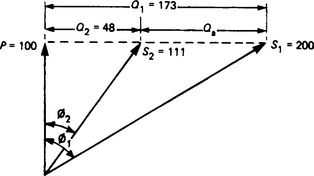
The required capacitor rating is therefore Qa = (Q1−Q2) = 125 kVAr. With a delta-connected 3-phase bank, each branch is rated at 125/3 = 42 kVAr. Table 38.2 gives the rating (in kilovars per kilowatt of load) to raise a given power factor to a selection of higher values. To obtain power factors approaching unity, the capacitor rating tends to be large, and it is usually uneconomic to correct to power factors greater than about 0.95.

For a rating Qa (in kilovar) the capacitance C (in micro farads) required is:
where f is the frequency (in hertz) and V is the line voltage (in volts).
38.14 Earthing
Earthing an electrical system is the process of connecting all metalwork (other than the electrical power conductors themselves) to the main body of earth. The aim is to convey to earth any leakage of electrical energy to the metalwork without hazard to personnel or equipment. An earthing system has two distinct but related parts: (i) a low-resistance conductor bonding the metalwork, connected to (ii) an electrode or array of electrodes buried in the ground. A ‘good’ earth may be difficult to achieve. The main factors in (ii) are the form and configuration of the electrode assembly, and the electrical resistivity of the soil.
38.14.1 Earth electrode
The ideal electrode is a conducting hemisphere. Current entering the ground from the hemispherical surface flows in radial lines, with concentric hemispherical equipotential surfaces decreasing in potential from the electrode. Such an electrode, or radius r in soil of resistivity ρ, has a resistance to the main body of earth given by:
Most of this resistance is located near the electrode surface, where the current density is greatest.
Practical electrodes are usually rods, plates or grids, and have a non-uniform current distribution in close proximity, but the more remote form the electrode system, the closer does the current distribution resembles that of the hemisphere. Formulae for estimating the value of R for typical configurations are given below. In each case ρ is the soil resistivity.
Single rod of diameter d and buried length l:
Multiple rods: it is seldom that a single rod can provide a low enough resistance and so arrays of rods have a relevance and are commonly used for substation earthing. The following formula is due to Tagg.1
For a group of n rods, each of resistance R1, in a hollow-square configuration with a spacing s between rods:
where α = rh/s, where rh is the radius of the equivalent hemisphere for one rod, and k is a factor depending on n.
Figure 38.13(a) gives values for rh for 25 and 12 mm diameter rods buried to varying depths. Variations in diameter have little effect on the overall resistance.

Figure 38.13 (a) Equivalent hemisphere radius v. length of rod electrode; (b) Factor k for hollow-square multiple-rod earthing array
Figure 38.13(b) gives values for factor k for varying numbers of rods.
Buried horizontal wire: buried wire or strip conductor is often used for earthing, particularly where ground conditions, as in hilly and mountainous country, make the driving of rods difficult or impossible. Formulae for the calculation of resistance values are complex, and it may be more helpful to quote values for particular conditions and leave the reader to make his own extrapolations.
For a conductor 2.5 cm in diameter, and buried about 1 m deep the resistance values shown in Figure 38.14 would apply. Resistivity is assumed to be 10000Ω-cm. Within reason, neither the depth of burying nor the diameter of conductor make significant difference to the resistance.

Since it is not always possible to lay an unlimited length of conductor in one direction, alternative configurations are often employed. For a total length of the above conductor of 150 m the resistance values would be as shown below. Note that for other values of ρ the figures in curves and tables should be multiplied by ρ/10 000.
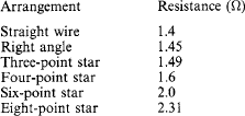
Plate electrodes: In the past considerable use was made of plate electrodes, but in general they are not as efficient or economical as rod or strip electrodes. When used, plate electrodes should be buried vertically with the top of the plate not less than 0.5 m below the surface. A simplified formula for the resistance of a plate electrode is:
where A, the area of the plate is in square metres.
The addition of coke having a relatively low resistivity, to a distance of 250 cm all round an iron plate electrode may reduce the resistance to earth by up to 50%, but coke is liable to increase corrosion both by chemical and electrolytic action. It must not be used with copper electrodes, and cables should not be run within about 6 or 7 m of the plate electrode.
All the above formulae for resistance values of earth electrodes should be viewed with caution, but once the value of the soil resistivity has been established they do provide the engineer with guidance as to the best method to adopt in any particular application. The following section deals with soil resistivity and its measurement, but it should be recognised that a major problem in pre-determining a value for earth electrode resistance is that in practice soil is seldom homogeneous, and values can vary widely, even within the fenced area of one substation.
Computer programs are now available to be used to design complex earthing systems.
38.14.2 Soil resistivity
The quality of the soil (sand, clay, gravel, rock, etc.) and its homogeneity determine its resistivity. Typical values (Ω-m) are:
| Rich arable soil, wet or moist | 50 |
| Poor arable soil, gravel | 500 |
| Rocky ground, dry sand | 3000 |
The resistivity is greatly affected by (i) moisture content, (ii) temperature and (iii) the presence of chemical contaminants. Thus, the resistivity rises substantially when the moisture content is below 30% and also when the temperature falls below about 10°C; but the presence of salts in the soil lowers the resistivity. It is evident that when soil is subject to considerable seasonal changes of climate, earthing electrodes should be deeply buried. In practical terms this suggests the adoption of rod electrodes, which can be driven to a depth where the moisture content and the temperature are more stable.
38.14.3 Electrode installation
For toughness and resistance to bending, driven electrodes are of steel rod, either galvanised or with copper molecularly bonded to the surface (Figure 38.15). Rods of diameter 15–20 mm can normally be satisfactorily driven. For adequate depth, rods supplied in standard lengths can be connected by screwed couplers or special connectors. In an installation requiring few rods, manual driving is easy and economic, but for hard compacted soil, and where many rods are concerned, it is preferable to use a power hammer.

Each rod should be driven until a minimum resistance reading has been reached, as described later. If the overall resistance of a given rod assembly is not low enough, additional rods may be driven, spaced typically at double the depth.
An earth electrode system must resist corrosion. Both galvanised and copper-clad steel rods have good corrosion resistance. The system must also retain its ability to carry large currents repeatedly throughout its life (30 years or more). Individual rods can deal with currents up to the fusing values, indicated in Table 38.3 for three typical durations.

Plate electrode: This has lost favour, being more expensive to install, more liable to corrosion, and buried in top layers of soil where stable soil-resistivity conditions are not readily achieved.
Grid electrode: Where the ground is rocky and the soil resistivity high, the only practicable method of obtaining an adequately low earth resistance may be by installing a grid of buried conductors.
Addition of chemicals: In general, this is of limited application, as chemicals tend to leach out, but where earthing is difficult, gypsum (a form of calcium sulphate) may be employed, mixed into the top soil or spread on the surface. Its value lies in its relatively low solubility in water. With moderate rainfall, gypsum percolates through the soil and continues to keep down the earth resistivity for the life of the electrodes. It has minimal corrosive effect, but sulphates do attack concrete.
38.14.4 Resistivity and earth resistance measurement
The soil resistivity must be known for the design of an earthing system to be determined and the earthing resistance of the system must be checked after installation. Both measurements involve passing current through the soil and measuring the volt drop. Composite instruments are available. Figure 38.16(a) shows the measurement of resistivity. The test prods are pushed into the ground to a depth not exceeding s/20, where s is the spacing between prods. The greater the spacing s, the greater the volume of soil concerned in the measurement. By repeating the test with various values of s, the uniformity of the soil can be assessed: reasonably constant values indicate good soil homogeneity.

Testing electrodes, individually or in an array, is shown in Figure 38.16(b), using the same test set with C1 connected to P1. Prods C2 and P2 should be far enough from the electrode system for accurate readings of resistance to be obtained. Provided that there is an adequate distance between C1 and C2, there should be a zone within which the potential prod P2 gives a constant reading.
38.14.5 Protective conductors
The earthing conductor connects the consumer’s main earth terminal to the earth-electrode system, but such disconnection must require the use of tools.
Under the IEE Regulations WR16, the circuit protective conductors (formerly the ‘earth-continuity conductors’) are those that join the consumer’s main earth terminal to all the exposed conductive parts of the system. The circuit protective conductor provides a low-impedance path for fault current, but must also ensure that no dangerous voltage can occur in metalwork in the vicinity of the fault. This is achieved by the connection of all extraneous metalwork to the main earth terminal: the provision covers such items as water and gas pipes, accessible structural steelwork, and central heating pipework, a requirement termed main equipotential bonding. The connections should be made as close as possible to the point of entry to the building concerned. Additionally, supplementary bonding is the connection of extraneous conductive parts that are accessible simultaneously with other conductive parts but are not electrically connected to the equipotential bonding: e.g. water taps, sink and bath waste outlets, central heating radiators.
The cross-sectional area (S in square millimetres) of the circuit protective conductor may be calculated as
where I is the current (in amperes) for a fault of negligible impedance, t is the operating time (in seconds) of the disconnecting device, and K is a factor depending on the material of the conductor, the insulation, and the initial and final temperatures. The operating time is usually t = 5 s for fixed and t = 0.4 s for portable equipment. A quick rule-of-thumb alternative to the formula is: S is the same as the cross-sectional area of the phase conductor where the latter is 16 mm2 or less; S = 16 mm2 for phase conductor sections between 16 and 35 mm2; and S one-half of the phase conductor section for larger areas.
For main equipotential bonding conductors, the area shall be not less than one-half of the main earthing conductor of the installation, with a minimum of 6 mm2 (10 mm for protective multiple earthing (PME). In general, supplementary bonding using 4 mm2 bare or 2.5 mm2 mechanically protected conductors should be acceptable.
38.14.6 System earthing
WR15 introduced a new designation for electricity supply systems to identify the type of earthing in use. WR16 continues this system, using a three or four letter code as follows:
First letter–‘supply’ earthing arrangement. T indicates that one or more points of the supply are directly earthed. I indicates that the supply is nowhere earthed, or is earthed through a fault-limiting impedance.
Second letter–‘installation’ earthing arrangement. T indicates that all exposed conductive metalwork is connected directly to earth. N indicates that all exposed conductive metalwork is connected directly to the earthed supply conductor (usually the neutral).
Third and fourth letters–earthed supply conductor arrangement. S indicates separate neutral and earthed conductors. C indicates combined neutral and earth in a single conductor.
In a TT system the exposed conductive parts of the installation are connected to an earthing electrode which is independent of the supply earth.
In a TN–S system the consumer’s earth terminal is connected to the supply authority’s protective conductor, usually the cable sheath and armouring, and so provides a continuous metallic path back to their earth electrode. The majority of installations with an underground supply are of this type.
In a TN–C system the neutral and protective functions are combined in a single conductor throughout the system. Typical is a system using earthed concentric wiring. If fed from a public supply authority, this system can only be used under special conditions and with the authority’s permission.
In a TN–C–S system the supply neutral and protective functions are combined and earthed at several points, often with an earth electrode at or near the consumer’s incoming terminals. The exposed conductive parts of the installation are connected to the neutral and to the supply neutral/earth at the consumer’s main earthing terminal. This system is also referred to as protective multiple earthing.
In an IT system the exposed conductive parts of the installation are connected to the consumer’s earth electrode, while the supply is either isolated from earth or connected to earth through an impedance. This form of supply cannot be used for public supply in the UK.
38.15 Inspection and testing
On completion and before energising, every installation must be inspected and tested to ensure that it complies with the appropriate regulations.
38.15.1 Inspection
WR16 calls for an inspection to be made of each installation before it is energised to ensure that the requirements of the regulations have been met. This must confirm that all electrical equipment is in compliance with the appropriate national standards, has been correctly selected and installed, and is in a safe working condition. The inspector/tester should understand how the installation functions and, to this end, he should ensure that his inspection covers such items as the identification and checking of the size of conductors, and the labelling of circuits, fuses, distribution boards and other switchgear. Finally, he should insist on the availability of diagrams, charts or tables describing the system under inspection.
38.15.2 Testing
Testing is required to ensure that the installation has been designed and installed (i) to give protection against electric shock during normal operation and during fault conditions, (ii) to ensure that it provides protection against overloads and short-circuits, and (iii) to provide protection against thermal effects–in particular, against fire and burns.
The IEE Regulations WR16 are quite specific regarding the items to be tested, and in particular they cite the following items which, where relevant, shall be tested.
Initial tests should be carried out in the following sequence:
(1) continuity of protective conductors, main and supplementary bonding;
(2) continuity of ring final circuit conductors;
(5) protection by separation of circuits;
(6) protection against direct contact, by a barrier or enclosure provided during erection;
(7) insulation of non-conducting floors and walls;
(9) earth electrode resistance; With the electrical supply connected re-check polarity before further testing using a suitable main voltmeter.
Tests must be carried out in the correct sequence. For example, it is important that the continuity (and, therefore, the effectiveness) of the protective conductors be checked before insulation tests are carried out, because an open-circuited protective conductor coupled with a low insulation resistance reading could make the whole system live at the test voltage during the insulation test.
In general, the application of any voltage to a system prior to connection to the mains must be done with care, to ensure that no danger to persons, property or equipment can occur, even if the tested circuit is defective. There is an increasing use of electronic components in present-day installations, and these can be damaged by relatively low voltages. Therefore the insulation resistance tests should be undertaken before the components are fitted, or they should be removed before testing commences.
38.15.2.1 Continuity
To check continuity it is not sufficient that a measurement be made across the end terminals. In the case of final ring circuits two measurements need to be made. Appendix 15 of WR15 detailed these, but in the bid for harmonisation this appendix has been dropped from WR16. The appendix proposed two acceptable methods, both assuming that an outlet is installed at or near the mid-point of the ring.
In method 1 the resistance of each pair of like conductors is measured with the two ends separated. After reconnecting the two conductors, a measurement is taken between the distribution board and the mid-point. After measuring and deducting the resistances of the test lead, it should be found that the first reading is four times the second reading (see Figure 38.17(a)).

In method 2 no long lead is needed to make contact with the mid-point of the ring. The continuity of each conductor of the ring circuit is measured between the ends of the conductor when separated, as for method 1. The conductors are then reconnected at the origin, all the connections at the mid-point outlet are short circuited and the continuity is measured between the phase and neutral terminals at the distribution board. This value should be one-half of the previous reading. Finally, the continuity is measured between the phase and the earth (see Figure 38.17(b)).
Continuity tests in protective conductors, particularly steel conduit, require the application of a current approximately 1.5 times the normal design current, using a voltage not exceeding 50 V a.c. or d.c. (If d.c. is used, verify that no inductor is included in the circuit.)
It will be appreciated that the resistances being measured in the continuity test will be small (e.g. between 0.1 and 0.5 Ω), and it is suggested that a testmeter with a range between 0.005 and 2.0 Ω would be useful.
38.15.2.2 Earth electrode
Methods of testing earth electrodes are described in Section 38.14.4 and illustrated in Figure 38.16.
38.15.2.3 Insulation resistance
Insulation resistance tests are carried out to verify that the insulation of the conductors and electrical accessories is satisfactory. A low reading would indicate a deterioration in the insulation, and a very low reading a total failure.
The test meter should provide a d.c. voltage of not less than twice the nominal voltage of the circuit under test (r.m.s. value for an a.c. circuit), but the test voltage need not exceed 500V d.c. for installations between 500–1000V.
Insulation resistance testing involves test of insulation resistance between conductors of different polarity and between all conductors and earth, and the value must not be less than 1 MΩ. A large installation may be tested by dividing it into groups, each containing not less than 50 outlets; the minimum insulation resistance demanded of each group is 1 MΩ. The term ‘outlet’ includes every point and every switch, except where the switch is incorporated in a lighting fitting, socket outlet or power-consuming apparatus.
During the insulation test to earth of a whole installation, all fuses should be in place and all switches closed, including the consumer’s main switch (if practicable). For the test (Figure 38.18) all conductors are bonded together at the load terminal of the main switch by means of a copper wire. The bonding wire is then connected to the ‘line’ terminal of the tester, the other terminal being solidly connected to the consumer’s earthing terminal. (When it is required to test to earth a live installation, the consumer’s main switch must be opened and the supply from the mains disconnected.) Portable apparatus should not be connected to the system, as it can be tested separately. Any item of fixed apparatus may be disconnected if desired and tested separately. With the test set connected as described above, the insulation resistance is measured. Where two-way switches are included in the circuits, two test readings should be taken, one switch in each pair being changed over for the second test to include the strapping wires in the test.

If the insulation resistance value exceeds the specified minimum, the system can be passed; but if not, further sectional tests will have to be made to locate the faulty section.
For insulation testing between conductors, if practicable all switches and circuit-breakers should be closed, and all lamps removed, together with all fixed appliances.
Any equipment disconnected before the tests are done, and having exposed conductive parts, should itself have an insulation value of not less than 0.5 MΩ.
38.15.2.4 Polarity
It must be checked that all fuses and single-pole circuit-breakers and switches are in the ‘line’ side, that the wiring of plugs and socket outlets is correct, and that the outer contacts of concentric bayonet and screw lampholders are in the neutral (or earth) side.
38.15.2.5 Earth-fault loop impedance
If a fault of negligible impedance should occur from a phase conductor to earth, the supply voltage will provide a fault current through the earth-fault loop. The significance of the earth-fault loop impedance is that it determines the current, and this, in turn, determines whether or not the protective device will operate quickly enough to meet the requirements of the relevant regulations.
Take, for example, the arrangement shown in Figure 38.19 and assume a fault to occur in an item of consumer’s equipment. The fault current IF will flow from the transformer, through the fuse and then via the casing of the equipment to the consumer’s earth, and thence back through the earth path to the transformer, such that IF = Vs/Z, where Z is the loop impedance. From Z calculations can be made for the overall performance of the system under fault conditions. For example, WR16 calls for all equipment connected to socket outlets to be cleared in 0.4 s or less when faulted. Other circuits supplying only fixed equipment are acceptable if the fault is cleared within 5 s. The regulations give tables of Z to meet these conditions.
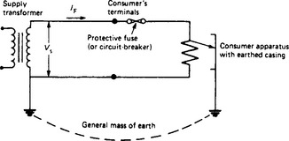
In practical terms, a phase-to-earth loop can be tested by connecting a known resistor R between the phase and protective conductors when the system is live with R typically 10 Ω. Measuring the volt drop v across it gives the current I = v/R. If the supply voltage is Vs, then Vs = I(Z + R) or Z = (Vs/I) − R, giving the required loop impedance.
The loop impedance must be tested using a phase-earth loop tester, which gives a direct reading in ohms. (The neutral-earth loop tester previously specified is no longe acceptable.) A dual-scale instrument covering 0–2 and 0–100 Ω is suitable.
38.15.2.6 Residual-current devices
Where the loop impedance is such that the required tripping times cannot be achieved, and in special cases (e.g. where the socket outlet in a house is used to supply gardening tools, or where the supply authority does not provide an earth terminal), a residual-current device must be fitted. It usually comprises coils on a magnetic circuit to carry the phase and neutral currents in opposing directions. In balanced conditions no magnetic flux is set up; but if a fault occurs on the system, even one of high resistance, the phase and neutral current imbalance induces an e.m.f in a third coil (Figure 38.20), tripping the circuit.
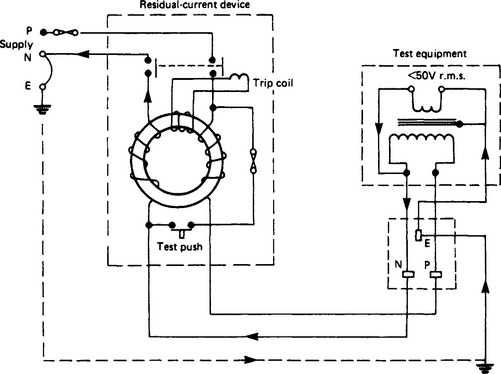
Figure 38.20 Residual-current device, showing test connections. The arrows show the path of the test current
To test the device, an a.c. voltage not exceeding 50 V r.m.s. obtained from a mains-fed double-winding transformer, is applied across the neutral and earth terminals. The device should immediately trip.
Fault-voltage operated circuit-breakers may alternatively be used, but are subject to tripping when faults occur outside the protected zone. If used, however, the earth-fault loop impedance including earth-electrode resistance must not exceed 500 Ω.
Whether or not this simple go/no-go test is sufficient is debatable. Test sets are available to measure the effectiveness of the RCD which simulates an appropriate fault condition with respect to time.
38.15.3 Test gear
Because the testing requirements of WR16 are stringent, the UK Electrical Contractors’ Association has suggested that the tester should equip himself with the following instruments, incorporating the features itemised.
Insulation-resistance/continuity tester–with 500/1000 V selector, analogue scale down to 0.01 Ω, battery power, push-button operation.
Digital milliohmmeter–with battery power, push-button operation, voltage protection indicator.
Polarity/earth-fault loop-impedance tester–with mains power, polarity indicator lamps, analogue low-resistance scale.
Dedication
This section of the Electrical Engineer’s Reference Book is dedicated to Jimmy Milne, BSc (Eng), C Eng, FIEE who has recently passed away and was not able to read my transcript of the updates from his original comprehensive work. I first met Jimmy when he was a Partner with Kennedy & Donkin Ltd, now Parsons Brinckerhoff Ltd, and I was an employee in the International Division. I am sure that all his professional colleagues will miss him.