
Insulation
AJ Pearmain, BSc(Eng), PhD, MIEE, CEng, Queen Mary and Westfield College, University of London (Sections 7.1 to 7.9)
A Haddad, Ing.d’Etat, PhD, Cardiff University (Sections 7.10 and 7.11)
Semi-fluid and fusible materials 7.5
Mineral waxes and blends 7.5.2
Miscellaneous fusible compounds 7.5.5
Treatments using fusible materials 7.5.6
Thermoplastic synthetic resins 7.5.8
Varnishes, enamels, paints and lacquers 7.6
Flexible sheets, strips and tapes 7.7.4
Sleevings, flexible tubings and cords 7.7.5
Moulded and formed compositions, plastics, ceramics, etc. 7.7.7
Composite solid/liquid dielectrics 7.8
Fundamentals of dielectric theory 7.10
Polarisation in dielectrics 7.10.3
Quantification of dielectric polarisation 7.10.4
Properties of dielectric materials 7.10.5
Example of ferroelectric material: Barium titanate and its applications 7.10.6
Polymeric insulation for high voltage outdoor applications 7.11
7.1 Insulating materials
Electrical insulating materials can be solid, liquid or gaseous, often in combination such as in oil-impregnated paper. The materials may be organic or inorganic and natural or synthetic. Both the electrical and mechanical properties of the materials are important, the variation of these properties with temperature being particularly important. In some applications the variation in electrical properties with frequency is significant and the chemical properties of the materials can often be vital because of the problems of compatibility between materials and of the behaviour of a material under fire conditions.
7.1.1 Classification
Insulating materials, especially those used in generators, motors, transformers and switchgear, are often classified on the basis of their thermal stability according to the scheme described in BS 2757:1986 and IEC 60085:1984. This scheme uses nine temperature classes, allocating materials to a class with ‘temperature limits that will give acceptable life under usual industrial conditions of service’. These standards recommend that temperatures above 250°C should increase in steps of 25°C and the class is designated accordingly.
![]()
Examples of materials in each class are given below.
Class Y: Unimpregnated paper, cotton or silk, vulcanised natural rubber, various thermoplastics that have softening points that would only permit their use up to 90°C. Aniline and urea formaldehydes.
Class A: Paper, cotton or silk impregnated with oil or varnish, or laminated with natural drying oils and resins or phenol formaldehyde. Polyamides. A variety of organic varnishes and enamels used for wire coating and bonding.
Class E: Polyvinyl formal, polyurethane, epoxy resins and varnishes, cellulose triacetate, polyethylene terephthalate, phenol formaldehyde and melamine formaldehyde mouldings and laminates with cellulosic materials.
Class B: Mica, glass and asbestos fibres and fabrics bonded and impregnated with suitable organic resins such as shellac bitumen, alkyd, epoxy, phenol formaldehyde or melamine formaldehyde.
Class F: As class B but with resins that are approved for class F operation such as alkyd, epoxy alkyd and silicone alkyd.
Class H: As class B but with silicone resins or other resins suitable for class H operation. Silicone rubber.
Classes 200, 220, 250: Mica, asbestos, ceramics and glass alone or with inorganic binders or certain silicone resins. Polytetrafluoro-ethylene.
The allocation of materials to classes such that their life will be adequate under usual industrial conditions means that the materials may not give adequate life if the service is unusually severe, e.g. equipment normally operated very near to full load. Conversely, it may be economical to use materials of a lower temperature class for equipment operated infrequently or normally operated at very low load.
7.1.2 Temperature index
Various suggestions have been made for alternative temperature classification systems, especially as techniques such as cross-linking enable the thermal stability of materials to be significantly improved and new high-temperature materials are constantly being developed. IEEE 98:1984 has withdrawn the term ‘Temperature Classification’ but the institution has suggested that a ‘temperature index’ related to the temperature capability of the material should be assigned to a material on the basis of experience or comparison with materials that have established indices. The index would be based on the life of the material in particular environmental conditions and would preferably be a number chosen from the series 90, 105, 130, 155, 180, 200, 220. For temperatures above 250°C, no index has been established yet.
7.1.3 Effect of frequency
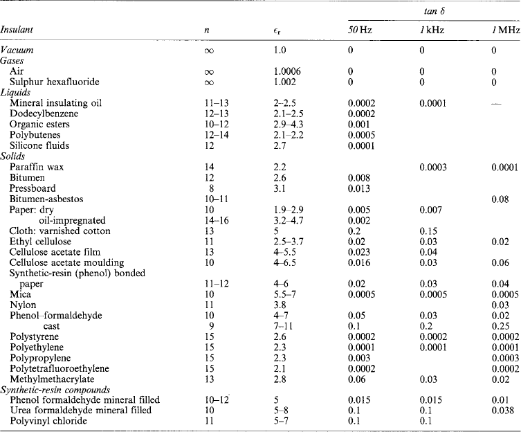
Insulating materials can have a very large variation in the dielectric loss and permittivity of the material with the frequency of the applied signal. Whilst this is important for insulation used in high-frequency electronics, it is not normally important in conventional power equipment, except for some condition of very fast transients. Table 7.1 shows the loss tangents (tan δ) at 50 Hz, 1 kHz and 1 MHz. Fortunately, the losses generally decrease with frequency for the materials that are used in electrical power insulation. Occasionally there can be significant changes at low frequencies and polymethylmethacrylate has a peak in dielectric loss at around 2 Hz, depending on temperature, where it increases by a factor of 3.
7.1.4 Fire behaviour
Despite the extensive precautions that are normally taken to prevent fire in electrical installations, fires do occasionally occur. There may be hundreds of wires bunched together in ducting and this presents serious problems in the event of a fire. One problem is that if fire propagates along the insulation, electrical systems will fail completely and these may be essential to the orderly shut-down of the equipment, or they may be responsible for important telecommunication systems. Another problem is that the fumes that are produced by combustion of the insulating material may be toxic and may also cause corrosive damage to neighbouring materials. It is therefore important that electrical insulation is assessed for behaviour in the event of fire. Some materials that have been used in the past are liable to produce toxic fumes. The former use of polychlorinated biphenyls as transformer insulation is a particular cause for concern.
Ease of ignition, or flammability, has traditionally been considered the most important property of a material when assessing fire hazards, but it has now been realised that this is only one of several factors that must be considered. The amount of heat, smoke and toxic gases released by the material and the way that the flame spreads in the material are all important. The traditional tests use very small quantities of the material which means that the information obtained is of limited value. More realistic tests require more specialised facilities and tend to be expensive to perform.
Gaseous insulation does not normally present any fire problem, although sulphur hexafluoride can decompose into toxic fractions under certain conditions. Commonly used insulating liquids, such as transformer oil, are flammable and so present a fire hazard. This is often unacceptable for transformers or switchgear situated in substations in blocks of offices or flats and alternative designs using air insulation or non-flammable liquids must be used. The same problems occur for equipment to be used in hazardous environments such as mines. Polychlorinated biphenyls were once used as non-flammable insulation in these applications, but the discovery of their toxic nature has required a search for alternative non-flammable liquids. Silicone oils are used but, although these are less flammable than transformer oil, they are still flammable.
Fire tests that are used to try to give more relevant fire hazard information for liquids use pools of the liquid from about 15 cm diameter to 9 m2 of burning liquid area.
Much of the work on fire behaviour is concerned with insulation for cables. Here the standard tests such as BS 6387:1994 only require a flame of between 650 and 950°C, depending on the fire resistance category, to be applied to about 600 mm of the cable for 3 h (only 20 min for the highest temperature) without the insulation failing. However, more stringent tests involving longer lengths of cable on cable trays in vertical ducts are often required so that the conditions met in situations such as power stations can be reproduced more accurately. A typical test involves 8 m of cable on a cable rack ignited by an 88 kW methane flame with a forced air draft to propagate the flame. Measurements are made of the distance that the flame spreads and the optical density of the smoke produced.
Tests are now being made of the heat evolution of materials in a fire. There is still a lack of agreement about exactly what tests are most appropriate and how reliably small-scale tests can be scaled to possible full-scale fire scenarios. There is particular lack of agreement about toxicity testing.
7.2 Properties and testing
The properties of insulating materials fall into the following categories:
Insulating materials may have to operate in the vicinity of apparatus producing high intensity radiation such as nuclear reactors, isotopes, microwave and electron generators, and considerable work has been done on the properties of materials under these conditions.
7.2.1 Physical properties
This is of importance for varnishes and oils. The density of solid insulants varies widely; in a few cases it is the measure of relative quality (as in pressboard).
7.2.1.2 Moisture absorption
This usually causes serious depreciation of electrical properties, particularly in oils and fibrous materials. Swelling, warping, corrosion and other effects often result. Under severe conditions of humidity, such as occur in mines and in tropical climates, moisture sometimes causes serious deterioriation; products made from linseed-oil varnishes, for example, are prone to complete destruction of the varnish film in a damp atmosphere. Fungus growth and electrolysis are other examples of effects due to moisture.
It is usual to determine the absorbency of solid materials by ascertaining the weight of water absorbed by a standard specimen when immersed for a specified period: however, the quantity of water absorbed is not a reliable criterion of the electrical performance of a material if taken in isolation. Some British Standard methods require that electrical tests, especially those for insulation resistance and loss tangent, be carried out immediately after the samples have been removed from water following a period of immersion of 24 h.
7.2.1.3 Thermal effects
These often seriously influence the choice and application of insulating materials, important features being: freezing point (of gases and liquids); melting point (e.g. of waxes); softening or plastic yield temperatures; flash point of liquids; ignitability, flammability, ability to self-extinguish if ignited; resistance to electric arcs; liability to carbonise or track; specific heat; thermal resistivity or conductivity; and coefficient of expansion.
7.2.1.4 Ageing
Although ageing has been placed in the physical-properties section, ageing involves changes in the physical, mechanical, electrical and chemical properties of the material when subjected to prolonged thermal and electrical stresses. In some applications mechanical stress may also be important.
A major part of life testing is the determination of the maximum temperature that a material, or combination of materials, can withstand for a long period without serious degradation of important properties. It is necessary for all components of an insulation system to be present during ageing tests because of the possibility of compatibility problems. Testing of this type is generally carried out on models made to reproduce, as far as possible, the conditions met in service. Such model investigations, often called ‘functional testing’, are generally accelerated by using temperatures considerably above those envisaged for service; but, provided that agreed procedures are used, it is often possible to extrapolate long-term results from comparatively short tests. A statistical technique that is often used for extrapolation is called Weibull statistics.
Thermal analysis tests that are routinely used to evaluate insulating materials are shown in Table 7.2. There is increasing interest in conducting ageing tests with a combination of heat and electric stress in order better to predict lifetime since there is an interaction between the decomposition products of electrical discharge and products released due to purely thermal effects in the material. Both increased temperature beyond that encountered in service and increased electric stress beyond the service stress can be used to accelerate ageing, but it is difficult to verify the prediction of service lifetime from the effect of a combination of acceleration techniques.
Table 7.2
| Technique | Parameter measured | Applied stress |
| Differential scanning calorimetry (DSC) | Energy necessary to establish zero temperature difference with a reference material | Environment heated or cooled at a controlled rate |
| Differential thermal analysis (DTA) | The difference in temperature between the material and a reference material | Environment heated or cooled at a controlled rate |
| Evolved-gas analysis (EGA) | Nature and quantity of volatile products formed | Heating |
| Thermally stimulated current measurement (TSC) | Polarisation or depolarisation current | Temperature change while electric field is applied |
| Thermogravimetry (TG) | Weight change with time or temperature | Heating or cooling |
| Thermomechanical analysis (TMA) | Mechanical strain | Mechanical vibration with heating or cooling |
7.2.2 Mechanical properties
The usual mechanical properties of solid materials are of varying significance in the case of those required for insulating purposes, tensile strength, cross-breaking strength, shearing strength and compressive strength often being specified. Owing, however, to the relative degree of inelasticity of most solid insulations and the fact that many are quite brittle, it is frequently necessary to pay attention to compressibility, deformation under bending stresses, impact strength and extensibility; tearing strength and ability to fold without damage are important properties of thin-sheet insulations such as papers, pressboards and varnished cloths.
Methods of test for the above properties are given in British Standards.
Many other mechanical features of insulating materials have to be considered, for example: machinability (especially as regards drilling and punching) and resistance to splitting, the latter being of particular importance in the case of laminated materials, wood and pressboards.
7.2.3 Electrical properties
The essential property of a dielectric is, of course, that it shall insulate. But there are properties other than resistivity that determine the insulation value: these are the electric strength, permittivity and loss tangent.
7.2.3.1 Resistivity
This concerns volume resistivity (a bulk property) and surface resistivity (concerning leakage current across the insulator surface between electrodes having a potential difference). The former is specified in ohm-metres (or megohm-metres) and the latter in ohms per square: the surface resistance between opposite sides of a square surface is independent of the size of the square. The properties are affected by surface or bulk moisture, so that measurements of insulation resistance of pieces of material or of insulated systems are often used to assess the state of dryness. Values of volume resistivity are given in Table 7.1.
7.2.3.2 Electric strength
Electric strength (or dielectric strength) is the property of an insulating material which enables it to withstand a given electric field magnitude without failure. It is usually expressed in terms of the minimum electric field magnitude (i.e. potential difference per unit thickness) that will cause failure or ‘breakdown’ of the dielectric under specified conditions, e.g. shape of electrodes, temperature and method of application of voltage, as these and several other features all influence the liability of the material to fail under electric stress. It is, therefore, important to state most of these conditions when quoting values of electric strength, and they have been standardised accordingly by BSI and others. The standard method for testing oils for electric strength is given in BS 148:1998, and that for proof tests on bitumen-based filling compounds in BS 1858:1975. Details of the standard method for proof tests on solid insulations, such as moulded compounds and sheet materials, are given in BS 5734:1990, BS 6091:1995 and BS EN 60243:1998.
The electric strength of most materials falls with increasing temperature and it is usual to carry out tests for this property at suitably elevated temperatures.
Other features which vitally affect the apparent electric strength are: the sharpness or radius of edges of electrodes; the waveform of the voltage (as breakdown is dependent on the peak value); the rate of increase in voltage and the time any voltage stress is maintained; the moisture content of the material; the thickness of specimen tested and the medium (usually air or oil) in which the test is made. Comparisons of electric strength are made generally by determining the electric stress that will cause failure 1 min after its application. Specifications frequently call for a proof test, the material being required to withstand for, say, 1 min a specified electric stress under controlled conditions.
In view of all the features which affect the apparent electric strength of dielectrics it is preferable to obtain comparative values, say, at a range of temperatures, thicknesses and test durations. Tests may be made with alternating or direct voltages; and it is now becoming more usual to test with lightning or switching-impulse voltages if the material is liable to sustain transient voltages in operation such as occur with overhead-line insulators, switchgear, power transformers and some machine windings. The object is to determine the highest stress that a material or assembly will withstand indefinitely. An indication can be obtained from a voltage/time curve (Figure 7.1) plotted from the stresses that cause breakdown in measured periods. The safe operating stress is then settled by experience, the use of safety factors, and the data from comparative tests. Figure 7.1 gives typical results of the variation of electric strength with thickness of specimen and with temperature.

7.2.3.3 Surface breakdown and flashover
When a high-voltage stress is applied to conductors separated only by air where they are closest together, and the stress is increased, breakdown of the intermediate air will take place when a certain stress is attained, being accompanied by the passage of a spark from one conductor to the other, i.e. the electric strength of the air has been exceeded. If the stress is sustained, this may also be followed by a continuous arc. The voltage at which this occurs is the sparkover or flashover value. Similar conditions can be obtained with oil as the insulant when a spark passes through the oil between the conductors.
In electrical assemblies where the live parts are separated by both solid insulation the ambient air, failure may take place either by breakdown of the solid material or by flashover through the air. Often the process involves surface leakage, deterioration and surface flashover. This phenomenon is generally due to the nature and design of the metal parts, as sharp edges of nuts and washers (for example) give local concentrations of stress. In addition, the onset of surface discharges at metal edges (which can initiate breakdown) is influenced by the permittivity of the dielectric material. The higher the permittivity, the lower the voltage at which flashover is likely to occur. Pollution on the insulation surface can reduce flashover voltage by a factor of 100. Insulating materials are sometimes tested for surface breakdown or flashover between two electrodes on a typical surface but, unless the material itself or its surface is poor electrically, flashover in air takes place in preference, usually at values of about 20 kV r.m.s. for 25 mm distance between two 38 mm diameter electrodes with fairly sharp edges.
7.2.3.4 Tracking
Leakage along the surface of a solid insulating material, often a result of surface contamination and moisture or of discharges on or close to the surface, may result in carbonisation of organic materials and conduction along the carbonised path. This is known as ‘tracking’. It is usually progressive, eventually linking one electrode to another and causing complete breakdown along the carbonised track. The methods for evaluating the resistance to tracking and erosion of electrical insulating materials are given in BS 5604:1986 and its IEC equivalent IEC 60587:1984.
7.2.3.5 Permittivity
This property is specific to a material under given conditions of temperature, frequency, moisture content, etc. When two or more dielectrics are in series and an electric stress is applied across them, the voltage gradient across each individual dielectric is inversely proportional to its permittivity. This is particularly important when air spaces exist in solid and liquid dielectrics, as the permittivities of these are always higher than that of air, hence the air is liable to have the higher stress and may fail and cause spark-over through the air space in consequence. The permittivity of dielectric materials is strongly dependent upon frequency with a tendency to fall to low values at higher frequencies. In the case of ferroelectric materials, increasing the temperature will lead to an increase in permittivity up to the ‘Curie Point’ after which permittivity falls rapidly with temperature.
Values of permittivity for some insulating materials are given in Table 7.1.
7.2.3.6 Dielectric loss
A capacitor with a perfect dielectric material between its electrodes and with a sinusoidal alternating voltage applied takes a pure capacitive current I = ωCV with a leading phase angle of 90°. In a practical case, conduction and hysteresis effects are present, the phase angle is less than 90° by a (normally) small angle δ. The power factor, no longer zero, is given by cos (90° − δ) = sin δ ![]() tan δ: the latter is called the loss tangent. The power loss is, to a close approximation, P = V2ωC tan δ where ω = 2πf: it is proportional to the square of the voltage and to the product ∈ tan δ, because the absolute permittivity ε determines the capacitance of a system of given dimensions and configuration.
tan δ: the latter is called the loss tangent. The power loss is, to a close approximation, P = V2ωC tan δ where ω = 2πf: it is proportional to the square of the voltage and to the product ∈ tan δ, because the absolute permittivity ε determines the capacitance of a system of given dimensions and configuration.
The loss tangent varies, sometimes considerably, with frequency and also with temperature; values of tan δ usually increase with rise of temperature, particularly when moisture is present, in which case the permittivity also rises with the temperature, so that total dielectric losses are often liable to a considerable increase as the temperature rises. This is very often the basic cause of electric breakdown in insulation under a.c. stress, especially if it is thick, as the losses cause an internal temperature rise with consequent increase in the dielectric loss, this becoming cumulative and resulting in thermal instability and, finally, breakdown.
Permittivity and loss tangent are usually determined by means of a Schering bridge (BS 7663:1993). For power devices such as cables and bushings, the test is made at 50 Hz; but for high-frequency equipment it is necessary to determine loss tangent and permittivity at much higher frequencies. BS 2067:1953 and BS 4542:1970 cover such measurements by the Hartshorn and Ward method at frequencies between 1 kHz and 100 MHz. Other methods are available for other frequencies (see IEC 60250:1969). Typical values of loss tangent and permittivity for some of the principal insulating materials used for high voltages and for high frequencies are given in Table 7.1.
7.2.4 Chemical properties
The chemical and related properties of insulating materials of importance may be grouped as follows:
Under (1) there are such properties as resistance to:
(a) the effect of oil on materials liable to be used in oil (in transformers and switchgear), or to be splashed with lubricating oil;
(b) effects of solvents used with varnishes employed for impregnating, bonding and finishing;
(c) attack by acids and alkalis, e.g. nitric acid resulting from electrical discharge, acid and alkali vapours and sprays in chemical works, and deposits of salts from sea spray;
(d) oxidation, hydrolysis and other influences of atmospheric conditions, especially under damp conditions and in direct sunlight; and
(e) effects of irradiation by high-energy nuclear radiation sources, e.g. neutrons, β particles and γ rays.
In group (2), typical effects of the insulating materials on other substances with which they may be used are:
(a) direct solvent action, e.g. of oils and of spirits contained in varnishes, on bitumen and rubber; corrosion of metals in contact with the insulation; and attack on other materials by acids and alkalis contained in the insulating materials in a free state;
(b) effects of impurities contained in the insulation; and
(c) effects resulting from changes in the material, for example acids and other products of decomposition and oxidation affecting adjacent materials.
These effects are generally referred to under the heading ‘compatibility’. If meaningful test results are to be obtained, all components of an insulation system must be present and they must have been treated in the same way as will be used in manufacture.
Group (3) includes such features as:
(a) oxidation resulting from driers included in varnishes;
(b) deterioration due to acidity (e.g. in oils, papers and cotton products);
(c) chemical instability of synthetic resins;
Most of these chemical properties are determined by well-known methods of chemical analysis and test. The principal tests are for acidity and alkalinity, pH value, chloride content in vulcanised fibre, and conductivity of aqueous extract (for presence of electrolytes). Some of these are dealt with in BS 5591:1978, BS 2782:1991, BS 5626−2:1979 and BS EN 1413:1998.
Increasing attention is being paid to chemical features of the raw materials and processes used in the manufacture of insulating materials—particularly varnishes, synthetic resins and all manner of plastics—and much research work is being carried out on these features and on the correlation of the chemical structure of dielectrics with their physical, electrical and mechanical properties.
7.3 Gaseous dielectrics
7.3.1 Breakdown mechanisms in gases
As a gas is a highly compressible medium, breakdown processes in gases depend on the density of the gas and values quoted for air in Section 7.3.2 must be corrected for the air density (d) relative to normal temperature and pressure (20°C and 1013 mbar, respectively):
where p is the pressure in millibars and t is the temperature in degrees Celsius.
A discharge in a gas and subsequent development into a visible spark or flashover starts with the production of electrons in the gas by emission from one of the electrodes, or even from cosmic rays. The initial eletrons are then multiplied by various processes of ionisation that give a growth in the current and lead, ultimately, to breakdown. In most gases, when an electron collides with a neutral molecule an extra electron and a positive ion will be produced, provided the energy of the original electron is higher than the ionisation energy of the molecule (Figure 7.2(a)) but in electronegative gases such as sulphur hexafluoride an electron can be captured by the molecule to give a negative ion (Figure 7.2(b)). This process is the opposite of electron multiplication so these gases have a high breakdown strength.

The breakdown strength of a gas is affected by the uniformity of the electric field, the waveform of the applied voltage, the support insulators and solid particle contaminants, in addition to the gas density. The effect of non-uniform field is particularly significant for d.c. insulation as the breakdown voltage is quite different depending on whether the point in a point-plane system is positive or negative. For large gaps the breakdown strength for the negative point is more than twice the voltage obtained when the point is positive.
In practical apparatus the breakdown strength of compressed gas can be reduced severely by the presence of dust and solid particles. Particles near an electrode can induce a spark at a substantially lower voltage than for a particle-free situation. In one study on sulphur hexafluoride, breakdown voltages were reduced to between 20% and 90% of the particle-free values, depending on the number and size of the particles present.
7.3.2 Air
Air is the most important gas used for insulating purposes, having the unique feature of being universally and immediately available at no cost. The resistivity of air can be considered as infinite under normal conditions when there is no ionisation. There is, therefore, no measurable dielectric loss, negligible tan δ, and a relative permittivity (for all practical purposes) of unity. The electric strength under normal atmospheric conditions is 30kV/cm (peak) for a uniform field. In a practical airgap the voltage gradient is a maximum at the electrode surfaces. The sparkover (breakdown) voltage of an air gap is therefore a non-linear function of its length. The gap geometry and configuration affect the breakdown voltage, and empirical expressions have been derived to account for the ‘gap factor’.
Partial breakdown of air, locally, often occurs when the voltage gradient in a particular region exceeds the critical value for air. This happens readily at points of electric flux concentration, e.g. sharp edges of metal parts. If this local breakdown becomes unstable—as it will when the voltage between conductors is increased sufficiently—sparkover will occur. This may be an isolated spark from one conductor to the other, and the intervening air then re-heals itself. If the voltage is maintained (or increased), the spark may be followed by a continuous stream of sparks.
Typical values of breakdown voltages for gaps of different forms and sizes of electrodes (under normal atmospheric conditions) are given in Table 7.3.
Table 7.3
Typical breakdown voltages in air under normal atmospheric conditions (kilovolt peak at 50 Hz)

Partial or complete breakdown of air in gaps can be influenced by suspending sheets of material at particular places in the electric field. In some cases, the sheets may be of metal, and in others of insulating materials; even woven fabrics can have an effect. The effect of this barrier is generally greater for more divergent fields. This solution can be useful where clearances are limited inside equipment, or particularly in high-voltage test areas.
For plane gaps, all gases exhibit a minimum breakdown voltage known as the Paschen minimum; this occurs at a given value of the product Pd of absolute gas pressure and gap length. For air this minimum occurs at Pd ![]() 6 (in torr-millimetre). Thus as the value of Pd is reduced from a higher region the breakdown voltage falls to the minimum value quoted, and further decrease in either P or d results in an increase in the voltage required to break down the gap. This explains why quite small gaps under conditions of high vacuum can sustain very high voltages. Table 7.4 gives the values of Pd and the minimum voltages for several gases.
6 (in torr-millimetre). Thus as the value of Pd is reduced from a higher region the breakdown voltage falls to the minimum value quoted, and further decrease in either P or d results in an increase in the voltage required to break down the gap. This explains why quite small gaps under conditions of high vacuum can sustain very high voltages. Table 7.4 gives the values of Pd and the minimum voltages for several gases.

7.3.2.1 Sphere gaps
As the electric strength of air is dependable, standard sphere gaps can be used as reliable and accurate means for measuring high voltages (Table 7.5), particularly where peak voltages are to be measured, as it is, of course, the peak value which determines the breakdown. Standard sizes of spheres are generally used as electrodes, as, provided the size is appropriate and proper precautions are taken (e.g. to avoid effects such as those due to the proximity of other objects and uncontrolled irradiation of the gap by other discharges), clean, smooth, metal spheres are most reliable as a means of determining high voltages; this is largely due to the absence of corona prior to flashover if the spacing does not exceed the radius of the spheres. Sphere gaps are suitable also for the measurement of impulse voltages. Voltages of about 2 kV and upwards can be measured reliably. BS 358:1960 gives detailed information on the effects of humidity, air density (or barometric pressure), etc. The effect of density is pronounced in the case of equipment used at high levels above 1000 m, in aircraft where altitudes up to 15 km may be met, or in spacecraft where outer space is an almost perfect vacuum.

7.3.2.2 Needle gaps
Humidity has here a strong influence on breakdown voltage where the electrode shape leads to field concentration. For this reason, as well as that of a degree of frequency dependence, needle gaps are unreliable for high-voltage measurements. Rod gaps (e.g. 12 or 16mm square-section rods with sharp corners) are used for chopping impulse voltages, but with these too a humidity correction is necessary.
7.3.2.3 Corona
This term is used to describe the glow or ‘brush’ discharge around conductors when the air is stressed beyond the ionisation point without flashover developing. It is of more or less serious consequence according to the application concerned. It causes a certain amount of energy loss with alternating current, which may become appreciable on high-voltage transmission lines. It produces radio interference and may initiate surface deterioration and breakdown on solid insulation surfaces. Corona is also known to produce secondary chemical effects.
In thin films, particularly in spaces between layers of sheet insulation, air can readily become ionised due to the electric stress across such spaces exceeding the critical value. This is often due to the fact that, with dielectrics in series, the stress in each section is inversely proportional to its permittivity. When the critical stress in the air or gas is exceeded, discharges occur (often called corona, ionisation, glow or brush discharges) and this causes splitting up of the gas molecules. In air this leads to the formation of ozone and nitrogen oxides which in the presence of moisture produce nitric acid. The ozone has, of course, a strong oxidising effect, but the more serious chemical effects of ionisation are those due to the nitrogen products, as the nitric acid attacks most of the organic insulating materials and causes corrosion of metal parts. The action of either or both the ozone and the nitrogen oxides on many materials is to cause decomposition and often the formation of acids; for example, oxalic acid, known for causing brittle fracture in polymeric insulators, by the oxidation of cellulose materials, and acetic acid from the decomposition of cellulose acetate.
In addition to the chemical effects, discharges in spaces, films or cavities within dielectrics can have serious consequences mainly due to the high energy in some of the individual discharges. Mechanical electrical and thermal damage can occur and breakdown in service may result after long periods. There has been considerable advance in the methods for detecting the presence of such partial discharges in various types of equipment especially where oil-impregnated paper dielectrics are used. Discharges within air or gas films in such material can cause severe damage often followed by complete breakdown.
7.3.3 Nitrogen
Instead of air, which is a mixture of approximately 21% oxygen and 79% nitrogen, nitrogen alone is sometimes used when there is a risk of oxidation of another material such as insulating oil. Nitrogen is often used in gas-filled high-voltage cables, as an inert medium to replace air in the space above the oil in some transformers, in low-loss capacitors for high-voltage testing, etc. There is no appreciable difference between the electric strength of nitrogen and that of air. Some results relating to the electric strength of nitrogen for uniform fields at pressures above atmospheric up to 20 atm are given in Table 7.6. Included are some similar results for carbon dioxide.

7.3.4 Sulphur hexafluoride
Sulphur hexafluoride is an electronegative gas which has come into wide use as a dielectric (in X-ray equipment, in waveguides, coaxial cables, transformers, etc.) and as an arc-quenching medium in circuit-breakers. Its electric strength is of the order of 2.3 times that of air or nitrogen, and at a pressure of 3−4 atm it has an electric strength similar to that of transformer oil at atmospheric pressure. The gas sublimes at about − 64°C and it may be used at temperatures up to about 150°C. Although the gas is considered to be non-toxic, non-flammable and chemically inert, under the influence of arcs or high-voltage discharges, there may be some decomposition with consequent attack on certain insulating materials and metals, and more importantly some recent environmental concerns. In circuit-breakers this problem is overcome by careful selection of materials (e.g. polytetrafluoroethylene for interrupter nozzles) and by the use of filters and absorbents to remove the products of decomposition after circuit interruption. Some figures relating to the electric strength of sulphur hexafluoride and mixtures of this gas with nitrogen are given in Table 7.7.
Table 7.7
Breakdown voltages of nitrogen and sulphur hexafluoride (kilovolts at peak): direct voltage and uniform field

Numerous other electronegative gases such as perfluoropropane (C3F8), octafluorocyclobutane (C4F8) and per-fluorobutane (C4F10) have been developed, but few have found such widespread use as sulphur hexafluoride. The main interest for these gases is as dielectrics in transformers, waveguides, capacitors, etc., but one difficulty is that the temperature at which condensation occurs may not be sufficiently low for safety in outdoor equipment likely to remain un-energised for long periods. This problem can be overcome partly by fitting heaters or by using admixtures with a more volatile gas (such as nitrogen). Addition of nitrogen often improves some of the characteristics, while at the same time reducing the overall cost. Some of these gases can be used at temperatures well above 200°C.
Most of the fluorinated gases have an electric strength between two and five times that of air or nitrogen under the same conditions but, as with sulphur hexafluoride, care must be taken to prevent high-voltage discharges or arcs in the gas because of the dangers of producing decomposition products. Recent research efforts in the electrical power industry focussed on improving the use of gas mixtures (essentially 90% nitrogen and 10% SF6), which are more environmentally acceptable. Gas insulated high voltage lines are now in operation using these gas mixtures.
Some electric machines and special devices have to operate in a gas other than air—for example, most refrigerator compressor motors operate in gaseous refrigerants mostly based on chlorofluorohydrocarbons (such as Arcton, Freon, etc.). These materials can act as solvents for some of the components used in insulating materials with consequent failure of the equipment due to blocked tubes and valves in the refrigerator circuit. Careful selection of materials for resistance to these fluids is essential.
7.3.5 Hydrogen
This gas is used as a cooling medium in some large turbo generators and synchronous motors; the main advantages are the efficient removal of heat and reductions in windage loss. Although there is a fire and explosion risk, troubles of this kind have been few during the many years that the gas has been used commercially for electrical machines. The electric strength of hydrogen at atmospheric pressure is about 65% that of air but most machines operate at pressures of 2–5 atm, and over this range the electric strength is higher than for air at atmospheric pressure. High-voltage discharges are thus not likely to be any more severe, and as discharges in hydrogen do not produce ozone or oxides of nitrogen, injurious effects are considered to be negligibly small.
7.3.6 Vacuum
Considerable investigation has been made into the utilisation of high vacua both for the insulation of equipment and as the interrupting medium in vacuum circuit breakers and contactors. The major advantage is due to the fact that very high electric field strengths can be achieved with a maximum operating pressure of 1 atm (negative), whereas with gases, very high operating pressures are generally essential and this complicates the mechanical design of the tank or other containing structure. Vast improvements in high-vacuum technology together with the need to replace oil-insulated switchgear has led to compact vacuum bottles used to retrofit old oil-filled circuit breakers.
7.4 Liquid dielectrics
The liquids which are most commonly used for electrical insulation are petroleum oils. For some applications these are being replaced by synthetic hydrocarbon oils, particularly as impregnant for oil-impregnated paper insulated power cables. Polychlorinated biphenyls (askarels) were widely used where non-flammable insulation was required for transformers, and for capacitor dielectrics. However, these have now been withdrawn for most applications because of environmental pollution effects and health risks. Silicone oils are now used for non-flammable transformer insulation. Capacitors often use silicone liquids or synthetic hydrocarbons as dielectrics, but various esters are now being introduced that offer a higher permittivity and hence a higher capacitance value for the same dimensions. An insulating liquid that is sometimes used is castor oil. The principal uses of liquid dielectrics are:
(1) as a filling and cooling medium for transformers and some electronic equipment, and as a filling medium for capacitors, bushings, etc.;
(2) as an insulating and arc-quenching medium in switchgear;
(3) as an impregnant of absorbent insulation, e.g. paper, porous polymers and pressboard—these are used in transformers, switchgear, capacitors and cables; and
(4) as a heat transfer medium in addition to its insulation rôle in power cables, especially in force-cooled high-pressure oil-filled cables.
The important properties of the liquid used vary with the application, but they include electric strength, permittivity, chemical and thermal stability, gassing characteristics, fire resistance and viscosity.
7.4.1 Breakdown mechanisms in liquids
Breakdown strengths of liquids are very dependent on liquid purity and all the breakdown mechanisms that are met in the practical use of liquids as electrical insulation are contamination mechanisms. Breakdown is caused by one of three contaminants; particles, water, or gas bubbles.
Particle-induced breakdown requires that there are dust particles, cellulose fibres from adjacent solid insulation or similar particles present in the liquid. If the particle has a higher relative permittivity than the liquid, electrostatic theory tells us that there will be a force acting on the particle moving it towards the region of greatest stress between the electrodes. If the particle contains moisture the force will be larger because of the high ∈ r value for water. Other particles will be attracted to the same region and they align end-to-end, eventually forming a bridge between the electrodes. Current flows along this bridge giving localised heating and breakdown.
Water itself is inevitably likely to be present in practical liquids. Careful procedures for filling equipment and maintaining desiccants at breathing points in the apparatus can normally keep moisture levels to less than 20 ppm. Any globule of water present in the liquid will become elongated in the field direction by the action of an applied field. Breakdown channels will propagate from the ends of the globule and produce total breakdown. The electric strength of an oil can be halved by the presence of 50 ppm of water. The presence of water will significantly increase the dielectric loss in the oil and reduce the breakdown strength.
Bubbles can be formed by gas pockets in pits or cracks on surfaces containing the liquid, or they can arise from dissociation of liquid molecules, or local liquid vaporization through electron emission from sharp points on an electrode. Such bubbles will become elongated by the field in a similar way to water globules. As the breakdown strength of the gas in the bubble will be much lower than that of the liquid, the field inside the bubble may exceed the breakdown strength of the vapour. This will give a spark in the bubble which may cause dissociation of some of the surrounding liquid to generate more gas. Eventually the bubble will become so large that a complete breakdown between the electrodes will ensue.
7.4.2 Insulating oils
The insulating oils used extensively are highly refined hydrocarbon mineral oils obtained from selected crude petroleum, and have densities in the range 860–890 kg/m3 at 15°C. Oil for transformers and switchgear is dealt with in BS 148:1998. A number of special mineral oils are employed for impregnated paper capacitors and cables and others—usually of higher viscosity and flash point—for rheostats and for filling bus-bar chambers in switchgear. Typical properties are given in Tables 7.3 and 7.9.
Table 7.9
Properties of typical oils and fluids

*mineral oil to BS 148:1998.
†S, liquid methyl silicone.
‡In standard test cell.
7.4.2.1 Electric strength
This is a property involving similar phenomena to spark-over in gases. On raising the voltage between two electrodes in oil, electrical discharges may first appear in the space surrounding the electrodes—particularly at sharp corners—and at a higher voltage, sparks pass across the intervening space between the conductors: these are often intermittent (‘pilot’) sparks, and, on raising the voltage further, a continuous stream of sparks usually occurs and may develop into an arc, with complete breakdown of the oil.
The electric strength is generally tested with electrodes consisting of two metal spheres of about 13 mm diameter separated by a gap of 4 mm. For clean, dry oil the breakdown voltage should be in the region of 100 kV r.m.s. or more, but careful treatment, storage and handling are needed to maintain this level. For the oil to comply with BS 148:1998, it should withstand for 1 min without breakdown 40 kV r.m.s. applied between the spherical electrodes under conditions laid down in the Specification.
The electric strength of insulating oil is strongly affected by impurities, especially water and particles of fibrous material. The latter are attracted to the testing gap by the electric field and readily align themselves across the shortest space. The presence of moisture in oils is shown by electric strength tests when particles of such solid impurities—particularly organic fibres—are present, the breakdown voltage being reduced considerably by even small quantities.
Typical values of electric strength in different conditions are given in Table 7.8. Water and other impurities can be removed from oil by means of filter presses, centrifuges or (where high voltages are concerned) the application of vacuum. In addition to removing moisture, the vacuum will remove dissolved gases, but it is necessary to heat the oil and to spread it out over a very large surface area to facilitate the process. Once oil has been treated in this way, it must be stored out of contact with air and for preference at a temperature higher than the ambient.

7.4.2.2 Viscosity
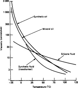
This property, particularly at low temperature, is of great importance in oils used primarily for cooling in transformers and rheostats, it being necessary for the viscosity to be sufficiently low to ensure the necessary convection at the operating temperatures. This property is usually determined by methods such as those described in BS 188:1997, and the viscosity is expressed in centistokes (cSt). Oil to BS 148:1998 has a maximum viscosity (kinematic) of 37 cSt at 21.1°C (70°F). This is approximately equivalent to 151 s at 21.1°C and 200s at 15.5°C (60°F) obtained with a Redwood No. 1 viscometer. Figure 7.3 gives typical viscosity–temperature characteristics.
7.4.2.3 Flash point
For standard oil this is not less than 146°C, and may be as high as 240°C for rheostats. These values refer to a closed flash-point tester.
7.4.2.4 Thermal properties
The specific heat is about 1900 J/(kgK) at 15°C and 2200 at 80°C. The thermal conductivity is of the order of 0.15 W/(m K).
7.4.2.5 Chemical stability
Insulating oils should be stable and not liable to deteriorate other materials or cause corrosion. The acidity is therefore closely controlled and oils are tested to ensure that they do not cause discoloration of copper. The worst feature of oils in this connection is the formation of sludge. This is mainly due to the oxidation of unsaturated hydrocarbons, particularly at high temperatures, and is accelerated by exposure of the oil to air and light, and (due to catalytic action) to copper. BS 148:1998 includes tests for acidity, discoloration of copper, tendency to sludge formation and development of acidity.
Useful guidance on means of maintaining insulating oils in service is given in the British Standard BS 5730:1979, for the Code of Practice for Maintenance of Insulating Oil with Special Reference to Transformers and Switchgear. This refers to oil supplied to BS 148:1998 and describes the nature of deterioration or contamination likely to occur in storage, or in the course of handling or in service. It also gives recommendations for routine methods of sampling and testing to enable the suitability of oil for further service to be determined.
BS EN 50195:1997 and BS EN 50225:1995 give guidance on the safe use of oil-filled equipment containing Askarel and PCB contaminations respectively.
The properties of a typical mineral oil, complying with BS 148:1998, are shown in Table 7.9.
7.4.3 Inhibited transformer oil
Oils operating at comparatively high temperatures, in the presence of oxygen and various catalytic materials, develop sludges and high acidity. These effects can be alleviated by adding various inhibiting substances to the oil, the most widely known being di-tertiary-butylparacresol used in quantities generally less than about 0.5% of the oil by weight. Materials of this type delay the point at which sludge and acid formation begin; but once the inhibitor has been used up, deterioration will proceed at the same rate as if no inhibitor had been used. For large power transformers, it has not been found necessary to use these inhibiting substances because of improvements in the construction which have reduced access of oxygen by conservators, hermetic sealing or the use of a nitrogen blanket above the oil surface. Another improvement has been the covering of copper surfaces so reducing the catalytic effect. For transformers operating under more adverse conditions of temperature such as distribution or pole-mounted units, a better case can be made for using inhibited oils.
7.4.4 Synthetic insulating liquids
Synthetic hydrocarbons are fairly widely used for power-cable insulation and as capacitor dielectrics. These are more expensive than petroleum oils but they generally have better electrical properties because of their lower contamination levels and they can have better gas-absorbing properties. A commonly used synthetic oil is poly-iso-butylene, commonly known as polybutene. Different polymer chain lengths can be produced giving a wide range of viscosities from low viscosity liquids to sticky semi-solids. The high molecular weight tacky and rubbery materials can be used mixed with oil, resin, bitumens, polyethylene and inorganic fillers to produce non-draining and potting compounds. Another synthetic oil that is used for cable insulation is dodecylbenzene, an aromatic compound. The physical properties are similar to mineral oils, but the viscosity-temperature characteristics show much higher low-temperature viscosity than comparable polybutenes. However, the gas-absorbing characteristics are good. Electrical properties are generally similar to mineral oils but the permittivity is somewhat higher for dodecylbenzene.
Polychlorinated biphenyls (also called askarels) have been used as high permittivity (3–6) fire-resistant insulating liquids since the 1930s but their effect as an ecological poison has limited their use to sealed equipment in recent years and all use of these liquids is being discouraged.
Silicone fluids (poly-dimethylsiloxanes) have been used as alternative fire-resistant insulating liquids, but their fire resistance is inferior to the askarels. They are generally gas evolving and their arc products can cause problems. However, they are very stable and have good electrical properties and are used in transformers and capacitors.
Several liquids have been developed as alternative high permittivity insulating liquids to replace the askarels for capacitor dielectrics. One possible group of materials is the organic esters. They have good viscosity temperature characteristics and are less flammable than mineral oil and can be either gas producing or gas absorbing, depending on their composition. When carefully purified, their electric strengths are about 20 kV/mm and dissipation factors average 0.001 at 20°C. Diesters have relatively high permittivities (4.3 for di-2 ethylhexylphthalate). Other liquids that may be suitable for electrical insulation are phosphate esters, halogenated hydrocarbons, fuoroesters and silicate esters. Castor oil is a good insulation material for d.c. stress with a permittivity of 4.7, but it has a high dissipation factor of 0.002 that makes it unsuitable for most a.c. applications.
BS EN 60867:1994 and BS 61099:1992 give specifications for unused liquids based on synthetic aromatic hydrocarbons and for unused synthetic organic esters respectively.
7.5 Semi-fluid and fusible materials
A few semi-fluid or semi-plastic compounds, and various fusible materials which are solids at normal temperature and melt to liquids of low viscosity or soften considerably with heat, are used principally in the following ways:
(1) for filling small cavities and large spaces, e.g. in metal-clad switchgear, transformers, cable-boxes and capacitors;
(2) for impregnating absorbent materials and windings;
(3) as the bond in laminated materials;
(4) as the basic material in moulding compounds; and
(5) for external coverings of parts and apparatus (i.e. envelopment and encapsulation).
The materials most commonly used for these purposes are bitumen, natural waxes, shellac, synthetic waxes and synthetic resins; with the exception of many of the latter, and shellac, these are all thermoplastic materials, i.e. they soften and melt on heating and solidify again on cooling without any substantial chemical change, and they can be re-softened or re-melted. In the case of some of the synthetic resins, especially those of the phenolic type, gradual hardening takes place as they are heated, and the melting point rises, so that, after being melted, solidification takes place on further heating, the material then becoming infusible: i.e. the process of melting and solidification on cooling is not repeatable; they are therefore known as thermosetting materials. Shellac also has thermosetting properties, but it requires longer heating to effect marked rise of melting point than in the case of many synthetic resins.
The properties of chief importance in such materials are: mechanical strength; electric strength; freedom from impurities; softening and melting temperatures; viscosity at pouring or impregnating temperatures; coefficient of expansion; and chemical effects on other materials.
Several materials which are semi-fluid at normal temperatures are used for filling and sealing purposes. For example: good grades of petroleum jelly of the Vaseline type are preferred to oil for filling apparatus and components where a liquid is undesirable, or where molten compounds cannot readily be poured or may affect other materials which are present (e.g. rubber and thermoplastic materials).
Various ‘semi-plastic’ compounds or cements, of a puttylike consistency, are also used for plugging and filling purposes, where semi-fluid and molten compounds cannot readily be applied. Some of these are almost permanently plastic and are therefore preferred where, for example, a certain amount of flexibility is required (e.g. where leads of coils may be moved slightly in assembly or service). Others may harden gradually in course of time (as in the case of ordinary putty), or they may harden quickly by chemical action (e.g. litharge and glycerine cement) or by heating—the latter usually being necessary with synthetic-resin compounds.
7.5.1 Bitumens
Highly refined bitumens, which are usually steam distilled, and of numerous grades, varying from semi-liquids to hard bitumens of melting point over 120°C, are used extensively for filling cable boxes, transformers and switchgear. These have high electric strength and are very inert and stable. As the coefficient of expansion is high, care has to be taken in filling large spaces to prevent voids and cracks on cooling. Some of the bitumens, especially those of high melting point, are rather brittle; all are soluble in oil, but they have excellent resistance to moisture. BS 1858:1973 deals with bitumen-base filling compounds for electrical purposes. Properties of typical bituminous compounds are given in Table 7.10. Some bitumens are used as ingredients in varnishes and paints, rendering these very resistant to moisture and chemical attack. A few impregnating compounds contain bitumens, especially those used for treating high-voltage machine bars and coils.

7.5.2 Mineral waxes and blends
Various mineral waxes such as paraffin, ceresine, montan and ozokerite—including microcrystalline waxes—also blends and gels of these, having melting points in the range 35–130°C, are used for impregnating capacitors, radio coils and transformers, also for other purposes such as cable manufacture. Properties of mineral waxes are given in Table 7.11.

7.5.3 Synthetic waxes
A few synthetic waxes—principally chlorinated naphthalene—with melting points up to 130°C have certain advantages over natural waxes, particularly higher permittivity which enables smaller paper-insulated capacitors to be made. Properties of a typical synthetic wax of this type are given in Table 7.11.
7.5.4 Natural resins or gums
These materials, which may be classified broadly as shellac, rosin (colophony), copals and gum arabic, are used principally as ingredients in varnishes or liquid adhesives. In some cases they are used direct, e.g. as powders, for a bonding medium between layers of mica which are hot pressed, but they are usually dissolved in spirit solvents, e.g. methylated spirits (or water in the case of gum arabic), and applied as a solution to mica, paper, etc., for subsequent laminating and hot rolling, pressing or moulding (see Table 7.11).
7.5.5 Miscellaneous fusible compounds
Numerous compounds of bituminous and other types are used for all manner of cavity-filling purposes, some (mainly rosin) are oil resisting and are employed where bituminous compounds cannot be used owing to the presence of oil, e.g. for bushings of oil circuit-breakers and oil-immersed transformers. Others are used for sealing over the tops of primary batteries and accumulators. Compounds containing beeswax are useful impregnants for small coils not exposed to heat, e.g. on telephone apparatus; and sulphur, ‘sealing wax’ and ‘Chatterton’s compound’ are examples of materials finding uses for miscellaneous applications where, say, the heads of screws in insulating panels and mouldings require to be sealed over.
7.5.6 Treatments using fusible materials
Treatments with bitumen, waxes, etc., usually consist of thorough vacuum drying of the coils, capacitors or other parts to be treated, followed by complete immersion in the compound while in a molten condition and at a temperature such that the viscosity is low enough to facilitate penetration; the molten compound generally being admitted to the impregnating vessel under vacuum. Pressure (up to 10 atm) is often applied during the immersion period to assist penetration. Such treatments enable spaces in windings to be filled thoroughly, and absorbent materials such as papers and fabrics are often well saturated with the impregnants, especially in the case of waxes. These treatments provide good resistance to moisture absorption and improve transference of heat from the interior of coils, also eliminating discharges in high-voltage windings and capacitors by the filling of air spaces.
7.5.7 Synthetic resins
An increasing number of the well-known synthetic resins, which form the basis of the principal ‘plastics’, are of great use to electrical engineers on account of their fusibility or softening characteristics at elevated temperatures, which enables them to be converted to desired shapes. The synthetic resins can be divided into two groups: thermoplastic and thermosetting (see Table 7.12).
Table 7.12
Thermoplastic and thermosetting synthetic resins
| Thermoplastic | Thermosetting |
| Polyethylene | Phenol formaldehyde |
| Polystyrene | Phenol furfural |
| Polyvinyl acetate | Urea formaldehyde |
| Polyvinyl chloride | Melamine formaldehyde |
| Acrylates | Silicones |
| Polyesters, alkyds, etc. (non-hardening) | Polyesters, alkyds, etc. (thermohardening) |
| Polyamides | Epoxy (epoxide) |
| Polyacetal | Polyurethanes |
| Polypropylene | Polyimide |
| Polycarbonate | Polyimide-amide |
| Polyphenylene oxide | Polyaralkyl ether/phenols |
| 4-Methylpentene-1 | |
| Acrylonitrile–butadiene–styrene |
Thermoplastic synthetic resins: In the case of most of the thermoplastic materials of this type, heating to temperatures within a certain range causes considerable softening and sometimes melting of the material to a viscous liquid. This enables them to be cast, formed, moulded or extruded into various required shapes by virtue of re-solidification on cooling again to normal temperatures. Some of the resins (e.g. acrylates and alkyd resins) have good adhesive properties and can therefore be used for bonding purposes either in the form of a solution or, more usually, by the application of heat. Layers of sheet materials, such as paper and fabric, can thus be bonded together into boards, simple mouldings, tubes, etc. The resins are often used alone, but more usually mixed with materials such as fillers and plasticisers, and in both varieties these synthetic materials are usually capable of being formed to all manner of shapes by the usual moulding processes (see Table 7.13).

Thermosetting synthetic resins: These enable useful compositions to be made, and withstand temperatures in excess of 100°C. The most widely used are the phenol formaldehyde type. The materials pass through three stages of physical condition:
(1) in which the resins are fusible at temperatures such as 80°C, and are soluble in suitable solvents;
(2) results from heating the stage (1) resin until it becomes relatively infusible and insoluble; and
(3) the infusible and insoluble state reached by continued heating after stage (2); no further change occurs and the materials are ‘fully cured’ or ‘completely polymerised’.
These physical stages make thermosetting resins suitable for three main uses.
(1) In spirit solutions; as ingredients in varnishes for impregnating purposes and the production of surface finishes; as enveloping, potting or encapsulating materials, and as ingredients in filling compounds.
(2) As adhesives for bonding layers of wood, paper, fabrics, etc., together to form laminated sheets, wrappings, and other simple shapes.
(3) As the basic material in moulding compositions for use in making articles by compression or injection moulding, extrusion or casting.
Properties of typical thermosetting resins of the phenol formaldehyde type, unfilled, are given in Table 7.14.
Table 7.14
Properties of unfilled phenol formaldehyde resins
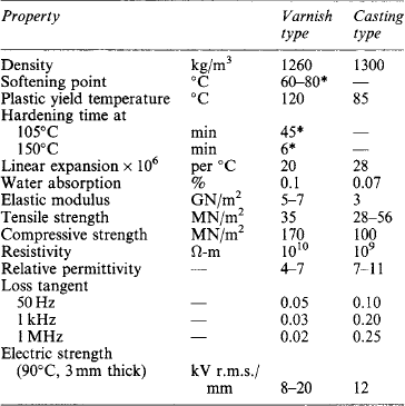
*In stage (1); other properties arc for stage (3) (see text).
Many of the thermosetting resins, e.g. phenol formaldehyde and melamine formaldehyde, require heavy pressure during the heating and hardening processes (2) and (3) above. Several resins requiring little or no pressure (polyesters, epoxies and polyurethanes) have been developed as ‘low-pressure’, ‘contact’ or ‘casting’ resins, or as ‘solventless varnishes’. These resins are initially in a low-viscosity liquid state, to which a ‘hardener’ or catalyst (e.g. a peroxide) is added. In some cases polymerisation sets in at normal room temperatures, or at temperatures of only 80–100°C, the hardening process taking place more rapidly as the temperature is increased. Thus the resins can be readily cast to required shapes in ‘moulds’, and can also be used for impregnating and coating windings as they readily fill interstices and do not leave voids on hardening owing to the fact that no volatile constituents evaporate—hence their use as ‘solventless varnishes’. Mixed with suitable fillers (e.g. glass fibres, asbestos or other minerals) or applied to fabrics, papers and other sheet materials (usually of glass fibres), they are used extensively for producing castings, mouldings and laminates of varying degrees of mechanical and electrical strength, sometimes in very large pieces which could not readily be made by normal moulding methods; they are usually referred to as ‘reinforced plastics’.
A brief description of the principal synthetic resins in electrical use is given below. Some are suitable for moulding with or without fillers, some for the preparation of laminated materials. Rod, sheet and tube forms are available in certain cases.
BS 1133-16:1997 deals with packaging adhesives and gives information on their characteristics and end use including advice on storage and precautions in use.
7.5.8 Thermoplastic synthetic resins
Polyethylene is waxy, translucent, tough and flexible, with a sharp melting point at about 110°C, and is used for high-voltage and high-frequency applications. It is readily injection moulded, extruded as wire coverings, and in sheet, rod and film form.
Polytetrafluoroethylene a white powder that can be moulded or extruded. It is highly resistant to moisture and chemicals, and withstands temperatures up to 250°C. It is used in high-frequency application.
Polystyrene softens at 70°C. It can be compression or injection moulded and may be used with a mineral filler to improve heat resistance.
Polyvinyl acetate and copolymers: Polyvinyl acetates are obtained from acetylene and acetic acid: they are used as adhesives and enamels.
Polyvinyl chlorides: These are obtained from the combination of acetylene and hydrochloric acid as a white powder used with stabilisers, plasticisers, etc., to produce various rubber-like materials that can be extruded as tubes for wire protection. Sheet and moulded polyvinyl chloride have a loss tangent too high for high-frequency use. Copolymers of the acetate and chloride forms are tough, rigid and water resistant and can be injection moulded.
Acrylates: The most important product is polymethylmethacrylate, a rigid glass-clear material with good optical, electrical and mechanical qualities. It can be obtained in sheet, rod and tube form, and as a moulding powder. Its low softening point (60°C) limits its application to moderate temperatures.
Polyethylene terephthalate: This has a sharp melting point at about 260° C and is formed into filaments for textile manufacture. Also extruded to form films. It has a high resistance to temperature and ageing and to water absorption. The textiles are suitable for class E insulation and, when suitably varnished, may withstand temperatures greater than class E.
Cellulose acetate and triacetate: These are also esters. Produced as lacquers, textiles, sheet, rod, film and moulding powder, they are suitable for machine windings. The acetate softens at 60–80°C, the triacetate at 300°C. The materials are available as fibrous cotton or paper tapes.
Polyamides: Super-polyamides are known as ‘nylon’: they produce monofilaments and yarns, with very good mechanical properties. The electrical properties are not outstanding, but nylon gives tough and flexible synthetic ‘enamel’ covering for wires. Films and mouldings can also be produced.
Polyacetal: The material has good dimensional stability and is tough and rigid. It can be injection moulded and extruded, and is replacing metal parts in relays.
Polypropylene: This material has a low density, dielectric loss and permittivity. Special stabilisers may be necessary when the material is extruded on to copper conductors.
4-Methylpentene-1 is similar to polyethylene and polypropylene and with similar resistance to chemicals and solvents. It is the lightest known thermoplastic. The high melting point (above 240°C) cannot be fully exploited because of softening and oxidation. Its permittivity and loss are low and remain fairly constant over a wide frequency and temperature range.
Polycarbonate approaches thermosetting materials in retention of stability up to 130°C. It is self-extinguishing and useful for structural parts, housings and containers for hand tools and domestic appliances.
Polyphenylene oxide is stiff and resistant to comparatively high temperatures. Its permittivity and loss tangent are fairly constant at frequencies up to 1 MHz.Acrylonitrile butadiene styrene has good dimensional stability and mechanical strength from −40 to 100°C.
7.5.9 Thermosetting synthetic resins
Phenol formaldehyde: These versatile resins are available in varnishes, adhesives, finishes, filling and impregnating compounds, laminated materials (boards, tubes, wrappings and sheets), moulding powders, and cast-resin products. The principal resins (Bakelite) are made by reacting phenolic material with formaldehyde. The final polymerising (‘curing’) time, which vitally affects the use, varies at 150°C from a few seconds to an hour or more. The resins are normally solids of softening point between 60 and 100°C. They are readily soluble in methylated spirit for coating papers, fabrics, etc., in the manufacture of laminates. Varieties are suitable for pouring molten into moulds followed by polymerisation. The most extensive use is as moulding powders with fillers (wood flour, powdered mica, fibres and colourings) to give mechanical strength and suitable electrical properties.
Phenol furfural is produced by the reaction of phenol with furfural, an aldehyde obtained by acid treatment of bran and fibrous farm waste. It is suitable for injection moulding.
Urea formaldehyde: The main use is as the binder of cellulose, wood flour or mineral powder in mouldings, made by compression at 115–160°C. Mouldings can be delicately coloured.
Melamine formaldehyde: Its properties are superior to those of the urea formaldehydes. It is suitable for mouldings for ignition equipment and has good resistance to tracking.
Silicones: These are organic compounds of silicon. By variation of the basic silicon–oxygen structure and of the attached organic groups, many different products can be made, including fluids, resins, elastomers and greases. Their main properties are water repellency (their hydrophobicity makes them a better choice for outdoor high voltage insulation), stability to heat, cold and oxidation, and good electrical properties maintained up to 200°C and higher. Some silicones can work continuously at 200°C and intermittently to 300°C: they can be applied to insulation in classes F, H and C. Silicone resins are used for bonding mica, asbestos and glass-fibre textiles and for producing compounds, varnishes, micanite, wire coverings, etc.
A number of silicone compounds can be used for filling and sealing where heat and moisture resistance are required. One such, of the consistency of petroleum jelly, is of use as a waterproof seal in high-voltage ignition systems: it protects cable insulation from moisture, oxidation and electrical discharges.
Polyesters: Alkyd resins are more rubbery than phenolic resins, have good adhesion and do not readily track; they are therefore of use for finishes and for varnishing glass fibre and similar material to produce heat-resisting varnished cloths. Unsaturated polyesters are useful for casting and potting, as solventless varnishes, and in the manufacture of laminates with glass fabric or mineral fillers.
Epoxies: The epoxy resins have become important as casting, potting, laminating, adhesive and solventless varnish agents. They have good electrical properties and resistance to heat, moisture and tracking, and adhere well to metal parts. They have been applied for high-voltage insulation in switchgear and for casting, in which case they are often mixed with mineral fillers. Earlier epoxy resins showed damage when subjected to severe weather and to high electric stress on creepage surfaces. New types have been based on cycloaliphatic resins which, because of the different molecular structure, produce less carbon during the passage of surface discharges and leakage currents under polluted conditions. Further improvements have been made in this application by using specially selected and treated mineral fillers which also reduce the effects of weathering and surface tracking. These products have many uses on high voltage outdoor equipment.
Polyurethanes, isocyanates: These are used mainly for coating fabrics (such as glass- and polyethylene-terephthalate fibre) to produce heat-resisting flexible sheet insulation and for coating wires.
Polyimides: These have been specially developed for use at high temperature as mouldings, films, wire enamels and laminate bondings. The materials can be used continuously at temperatures in the 200–240°C region; and for very short periods, they can withstand temperatures up to 500°C without apparent damage. Their mechanical and electrical properties are good and their resistance to most chemicals, solvents and nuclear radiation is excellent. Polyamide imide resins are similar to the polyimides and are available in the same forms. The performance at high temperatures is marginally lower but the resins are simpler to use in the manufacture of laminates, and have longer shelf-life.
Polyaralkyl ether/phenols: These have a high-temperature performance not quite as good as that of the polyimides, but are cheaper. The resins can be used as bonds for glass and asbestos laminates and mineral filled moulding powders are available. A high proportion of room temperature strength is retained at temperatures up to 250–300°C and long-term operation at temperatures of 220–240°C is possible. Their resistance to most chemicals and solvents is excellent.
7.5.10 Encapsulation
When electronic or electrical components and circuits must resist the effects of climate, industrial atmospheres, shock or vibration they may be encapsulated. They are then generally known as ‘potted circuits’.
Certain thermosetting synthetic resins are of the greatest use as they can be easily poured from low-viscosity liquids and made to set without the use of pressure and, in some instances, with very little heat. A suitable material must: (1) be a good insulator over a wide range of temperatures (volume resistivity say 106Ω-m); (2) polymerise or set without spitting off water or other products; (3) have low viscosity at pouring temperature, low vapour pressure, and freedom from deleterious side-effects on personnel who are using it; (4) show small shrinkage, especially when changing from the liquid to the solid state; and (5) must adhere to all materials commonly found in electrical equipments, e.g. to brass, solder, steel and insulating boards. Only the epoxy resins possess all the essential requirements for successful encapsulation and even these need an inorganic filler to obtain the best heat resistance, low shrinkage, good electrical properties and high thermal conductivity.
The epoxide resins of use in potted circuits are derived from a condensation reaction between epichlorhydrin and bisphenol A. They are cross-linked with aliphatic or aromatic amines, acid anhydrides and a few other chemical compounds to give thermally, electrically and mechanically stable resins. The addition of inorganic fillers improves them and reduces their shrinkage, tendency to crack at low temperatures and cost. The mixture of resin and cross-linking agent (known as a hardener) is called a system. An accelerator may be added, as well as various diluents, both reactive and non-reactive. Accelerators and promotors alter the speed of reaction and the pot life.
Typical potting formulations, in parts by weight, are:
(A) resin 100, hardener 10, mica flour filler, 15; and
(B) resin 100, hardener 82, quartz flour filler 375, accelerator 1.
Formulation A is satisfactory for small units of about 0.1 kg of mixture. It sets at room temperature, but is post-cured at an elevated temperature dependent on the heat resistance of the included components; 18 h at 65°C is usually satisfactory. Such a unit is suitable for small electronic packages containing small components, including semiconductors. Larger masses, depending on their geometry, may exhibit a strong exotherm (i.e. generate heat) which may damage the included components.
Formulation B is used hot (usually at about 65°C) and is very fluid at this temperature besides possessing a long pot life. This makes it suitable for the potting of transformers. Vacuum impregnation is essential to eliminate voids, which would result in ionisation and corona discharges. The large amount of filler greatly improves the thermal and mechanical properties and allows a larger casting to be produced without a high exotherm. Again, a post-curing cycle is essential to bring out the best properties; in this case about 18 h at 120°C is satisfactory and will produce a material with high volume resistivity and heat resistance. The pot life of this mixture is about two hours at 65°C, which may be compared with formulation A whose pot life is less than half an hour at room temperature.
In use the resin and dried filler of A are mixed together and stored under vacuum or in a desiccator until used. The hardener is added and thoroughly mixed just before pouring into the mould or other article to be potted. It stands at room temperature to set or ‘gel’ and is subsequently post-cured; this latter process may be carried out after removal from the mould if required.
For formulation B the resin, hardener and dried filler are all mixed and stored as before, and the accelerator is added to the mixture just before use and heated to 65°C. It is poured into the mould or other article. For transformers this is usually done under a vacuum of about 1 mmHg to 1 cmHg. Although a large amount of inorganic filler is used, this is filtered to some extent by the windings of the transformer so that the insulation between turns is mostly of unfilled resin, giving high breakdown strength and freedom from corona discharges. Good adhesion at the terminals is ensured by the nature of the resin system, but this also means that it sticks to the mould unless a release agent is used. Various preparations are used, including mixtures of high polymers, silicones, greases and waxes. The agent must be confined to the mould and not allowed to contaminate the components inside the casting.
The requirements of low shrinkage and low exotherm have been stated. The effect of the former is to damage components by compressional forces and is particularly severe on some nickel–iron alloys used in making inductors; thin-film resistors and capacitors are also vulnerable to this form of damage. Isolating the components from the resin by means of low modulus materials can appreciably reduce this defect. The heat of reaction (exotherm) is also damaging to organic materials and to semiconductors; this often results in a loss of volatile matter causing shrinkage and the effects already noted above.
All adhesives contain polar bonds in their molecular structure. These give rise to changes in dielectric properties as the frequency and temperature varies, causing the electrical behaviour of the components inside the casting to change as the frequency and temperature changes.
Another disadvantage of potted circuits is that they are irreparable: they must be designed as ‘throw away’ subunits and made at an economical price. For this reason they are rarely used in domestic applications such as radio or television, but are of particular use in military electronics, for machine control and similar purposes where the utmost reliability is essential and first costs are relatively unimportant.
7.6 Varnishes, enamels, paints and lacquers
Numerous liquid materials, which form solid films, are used extensively in the manufacture of insulating materials and for protecting windings, etc.
7.6.1 Air-drying varnishes, paints, etc
One class of air-drying varnishes and lacquers consists of plain solutions of shellac, gums, cellulose derivatives or resins which dry (e.g. in 5–30 min) and deposit films by evaporation of the solvent. Other air-drying varnishes and paints form films which harden by evaporation of solvent accompanied by oxidation, polymerisation, or other chemical changes which harden and toughen the film. These processes take several hours.
7.6.2 Baking varnishes and enamels
Where the toughest and most resistant coatings are required, baking varnishes and enamels are used, the evaporation of solvents and hardening of the material being effected by the application of heat. Typical varnishes of this class require baking at, say 90–110°C in a ventilated oven for 1–8 h. During the baking (or ‘stoving’) the hardening is usually caused by oxidation, but in some cases polymerisation takes place. The latter process does not require oxygen and, provided that the solvents are first removed, drying can take place within the interior of coils. In consequence these varnishes are preferred to the oxidising types which skin over and leave liquid varnish underneath. Such thermosetting impregnating varnishes are used extensively for treating coils, and the windings of small machines and transformers.
7.6.3 Solventless varnishes
Thermosetting synthetic resins are used for impregnating windings and, owing to the manner of hardening during which little or no volatile matter is evolved, spaces in the interior of windings can be filled completely with non-porous resin. One type consists mainly of oil-modified phenolic resins, similar to the oleo-synthetic resinous varnishes but without solvents; they are consequently termed solventless varnishes. When used for impregnating they are in a hot liquid condition, the material solidifying within the winding by baking after impregnation.
Specially formulated low-viscosity resins of the polyester or epoxy type are also used for impregnation. It is possible to use solventless resins in conveyorised plants where the parts are dipped in the resin, allowed to drain and then passed through a heated tunnel to cure the resin. In other cases, particularly for tightly wound apparatus, the parts are treated in the resin using a vacuum-pressure process to ensure that a high level of impregnation is attained.
The most recent development in treating industrial machine windings is the ‘trickle’ process. The wound part is heated and mounted at a slight angle so that it can be rotated slowly about its axis. A metered quantity of the resin is allowed to trickle on to the winding and under the action of gravity and the rotational forces, the resin penetrates to all parts of the winding and completes the impregnation. It is possible to completely fill the interstices of the winding without loss of resin by draining. Radiant heat may be applied to complete the cure while the parts are rotating, or heating currents may be circulated through the winding. Trickle impregnation can be performed automatically and the process can be completed in a few minutes without removing the wound parts from the production line.
7.6.4 Silicone varnishes
Varnishes based on silicone resins are in general use. Some include other resins, etc., such as alkyd resins. Silicone varnishes are used for impregnating and coating cloths, tapes, cords, sleevings, papers, etc., made from glass fibres and polyethylene-terephthalate fibre; for bonding mica, glass cloths and papers, e.g. for slot insulation; for coating and bonding glass; for ‘enamelling’ wires for windings; and for all manner of impregnating, bonding, coating and finishing purposes such as the treatment of windings for classes B, F and H.
7.6.5 Properties of varnishes, etc
The properties of the solid films formed after drying and hardening varnishes, paints, etc., naturally depend mainly on the principal basic materials, e.g. gums, resins and oxidising oils. Other materials added are: ‘driers’ to accelerate drying; ‘plasticisers’ to improve the flexibility; and pigments to provide the required colour and improve the hardness and filling capabilities.
Treatments of windings and insulation parts, by varnishes, enamels, lacquers or paints, take the form of (a) application of external coatings—chiefly for providing protection against moisture and oils, or (b) impregnation of windings and absorbent materials, for rendering them less susceptible to moisture and improving their electrical and heat-resisting properties. Both air drying and baking materials are used for (a), but only baking varnishes and enamels are suitable for (b). In practically all cases, thorough drying prior to application of the varnish is essential as for compound treatment, but with varnishes, extra care is required to remove excess varnish by proper draining and to extract solvents thoroughly before hardening the material by baking. This is usually done in well-ventilated ovens at temperatures of 80–150°C and sometimes by the application of vacuum for a period to assist the removal of solvent. These processes are not required when solventless varnishes are used. In the case of silicone varnishes, the solvents must be removed and baking must then be carried out at temperatures in the range 150–260°C.
Insulating varnishes are the subjects of BS 5629:1979, BS 7831:1995 and BS EN 60464:1999. Typical properties are listed in Table 7.15.
Table 7.15
Properties of typical varnishes

A1: spirit shellac/methylated spirit
A1: spirit shellac/methylated spirit
A2: oil and resin/petroleum spirit
B2: black bitumen/petroleum spirit
B3: synthetic resin and oil/toluol
*After 24 h immersion in distilled water.
7.7 Solid dielectrics
The many solids that can be used for insulating purposes are considered in groups according to their form.
7.7.1 Breakdown in solids
The breakdown strength measured for a solid is very dependent on the time of application of the voltage. Strengths of 100 kV/mm to 1.5 MV/mm can be obtained for short pulses under carefully controlled laboratory conditions, but in practical insulation systems breakdown strengths of only about 20 kV/mm are obtained. The high laboratory value is known as the intrinsic electric strength of the material, with breakdown due to electronic processes. In practical insulation, however, breakdown is due to: erosion, thermal effects, electromechanical effects, or treeing.
Discharge/Erosion breakdown originates at internal voids in the insulation. These are left at the fabrication stage and all solids contain them, although in a high-quality material they will be very small (microvoids). These voids will be filled with air or another gas with a permittivity and dielectric strength much lower than that of the solid. Electric field enhancement in the micro-void takes place due to the relative permittivity difference in the two media. Consequently, the gas filling the void will break down at a voltage lower than the normal breakdown strength of the material and this partial discharge will erode the solid at the ends of the spark on the surface of the void. These discharges will occur twice for every cycle of an alternating supply, so over a period thousands of millions of these discharges will occur in a cavity. The erosion effects of these discharges can eventually be sufficient to cause complete failure of the insulation. This is the primary reason why the insulation of a component may fail after a number of years in service.
Thermal breakdown is breakdown caused by internal heating in the insulation due to dielectric loss. Insulating materials are not perfect capacitors and they do have internal energy losses. The quality of the insulation is often measured in terms of how small these losses are, with the loss factor tan δ, where (90-δ) is the phase angle between the voltage and current for a sample of the material, commonly used as the parameter to assess the losses. This energy dissipated within the insulation will cause heating and electrical insulation is usually a poor thermal conductor, so a significant temperature rise in the insulation will be produced. In some circumstances the internal losses may increase as the temperature increases and a thermal runaway situation results. The temperature of the material will rise, losses will increase and the temperature will rise further until the material fails. Thermal breakdown is most likely to occur in power cables operated beyond their power rating, polymers operating near their softening points or in high-frequency applications.
Electromechanical breakdown results from the mechanical forces that an applied electric field produces. This force will reverse for every cycle of the applied voltage and can produce cracks or other damage in solid insulation.
There are two types of treeing breakdown. The first type originates at sharp points on electrodes which act as the root of fine branching channels that propagate through the insulation. Over a period of time these fine channels gradually extend towards the other electrode until complete failure of the insulation occurs. This is another mechanism which can produce failure after equipment has been in service for months or years. The second type of treeing is known as water treeing and only occurs when there is water in contact with the surface of the insulation. Microscopic damage to the insulation gradually spreads out from a high-field region until failure of the material occurs. A major difference between this type of treeing and the previous one is that the damage cannot be seen once the material has dried out.
7.7.2 Rigid boards and sheets
7.7.2.1 Panels and simple machined parts
Asbestos-cement boards (3–100 mm) are incombustible and arc-resistant, and are used as barriers and arc-chutes. Glass-bonded mica, in sheets 0.5 m × 0.4 m of thickness 3–30 mm, are especially good for high-frequency, high-voltage and high-temperature (400°C) application. Micanite, mica splittings bonded with shellac or synthetic resins, in thicknesses up to 25 mm or more; also mica-paper materials, comprising layers of mica-paper bonded under heat and pressure with a wide variety of resins, including high-temperature types (see Table 7.16).

7.7.2.2 Pressboard
This is a paper product, widely used in oil-immersed transformers in thicknesses up to 10 mm. Thicker boards are built up by bonding plies together with adhesives such as phenolic resins or casein. In the USA, pressboards are available with special treatments which are claimed to permit operation at higher temperatures than untreated materials. In one case the material is treated with an amine; in another the cellulose molecule is modified chemically by cyanoethylation.
7.7.2.3 Laminates
These are sheets of paper, fabric, etc., bonded with gums, shellac or synthetic resins under heat and pressure usually in hydraulic presses. Resins can be phenol formaldehyde, melamine formaldehyde, polyester, epoxy, silicone, polyimide, polyamide imide, etc. These are some of the most useful insulating materials for panels, terminal boards, coil flanges, packings, cleats, slot wedges and many other uses. The principal varieties are: synthetic resin bonded paper in thicknesses of 0.2–50 mm in several grades. Synthetic resin bonded cotton fabric (0.2–100 mm), the most common being bonded with phenolic resin, but an epoxy bonded type has been developed; both are tough and have good machinability.
Curves for water absorption for some types of s.r.b. paper and cotton fabric are given in Figure 7.4. Synthetic resin bonded asbestos paper, fabric and felt, used for low-voltage work at somewhat higher temperatures, e.g. 130–150°C. Synthetic resin bonded glass fibre, bonded under heat and pressure with synthetic resins of the melamine, epoxy, phenolic, polyester and silicone types in the thickness range up to 12.7 mm. Most of these materials have good electrical and mechanical properties and low absorption (see Table 7.17). Similar materials are available where the reinforcement is a web of random laid glass fibres—known as mat. These materials are generally cheaper than those based on fabrics, although some of the properties are not as good. By arranging for a preponderance of the fibres to be in one direction, it is possible to produce boards with very good mechanical properties in certain planes. Such boards bonded with epoxy resins can have flexural strengths as high as 1300 MN/m2 and flexural moduli approaching 5 GN/m2.
Table 7.17
Properties of synthetic resin bonded glass fabric laminates*

*EP, Epoxy resins; MF, melamine formaldehyde resins; PF, phenol formaldehyde resins; PR, polyester resins; SIL, silicone resins. Test methods of BS 2782:1995 and BS 3953:1990.
†Per 12.7 mm width, 3 mm thick.
‡R.m.s. for 25 mm length at 90°C.

Figure 7.4 Water absorption of typical synthetic resin bonded paper and fabric boards: (a) type I; (b) type II; (c) type III; (d) type IIIA
In addition to the resins mentioned, high-temperature materials are now available which are thoroughly suitable for use with all forms of glass and other reinforcement. Some of these materials give thermal lives as good as the silicones but with mechanical properties more nearly equal to the epoxies. Typical materials in this class are resins based on acrylics, polyimides, polyamide imides and combinations of polyaralkyl ether with phenols, etc. Also, resins are now available for all types of laminate especially phenolic, epoxy and polyester where, in order to decrease the fire risk, the resin has flame-retardant properties (see Table 7.18).
Table 7.18
Properties of typical high-temperature laminates*

*A/AP, acrylic + asbestos paper; S/AP, silicone + asbestos paper; P/GF, polyimide + glass fabric; PI/GF, polyamide imide + glass fabric; PEP/GF, PEP/AF, polyaralkye ether/phenol + glass or asbestos fabric. r, room temperature.
†Per 12.7 mm width.
‡R.m.s
Synthetic resin bonded (SRB) laminates of various types are made with a thin layer of copper (or other metals such as nickel and cupronickel) bonded to one or both surfaces. These materials are known as metal clad (or specifically copper clad) laminates and are used for printed circuit board applications.
A material in rigid form is produced by bonding high-density polyamide paper plies by heat and pressure only to give a tough, strong board with a long life at temperatures up to 220° C.
Other materials from the wide range of plastics are available as rigid boards or sheets although most of these materials are thermoplastic. Often such materials are moulded to produce finished products but it is possible to cut shapes and panels from sheets. Typical materials are based on polyvinyl chloride, acrylonitrile–butadiene–styrene, polyolefin, polymethylmethacrylate, etc. Many are flame-retardant or self-extinguishing; and reinforcing materials such as glass and asbestos fibres, glass spheres and mineral fillers can be added to improve mechanical properties and resistance to high temperatures. The well-known material ebonite, a mineral-filled rubber-based material, was a forerunner of this class.
The properties of typical sheets and boards are given in Table 7.19.
Table 7.19
Properties of typical rigid sheets and boards

VF,BS 6091 Parts 1 and 2:1995, Grey Vulcanised Fibre.
PB,BS EN 60641:1996, Absorbent Pressboard Grade II.
SP,BS 5102:1974, Synthetic Resin Bonded Paper Type I.
SW,BS 2572:1990 and BS EN 60893-Part 2:1995, Synthetic Resin Bonded Wood.
SF,BS 2572:1990 and BS EN 60893-Part 2:1995, Synthetic Resin Bonded Fabric. Type 3B.
*Varies considerably with relation of grain to lamination.
†Dry: 4 when dried and oil-impregnated.
‡Dry: 0.04 when dried and oil-impregnated.
7.7.3 Tubes and cylinders
Tubes and cylinders can be produced by several methods. Materials capable of being moulded can be treated by compression or casting techniques. Many plastics can be extruded. Vulcanised fibre tubes are wound from paper treated with zinc chloride solutions. Laminated materials are generally wound on special machines with heated rollers while tension and pressure are applied to consolidate the layers. In this way SRB paper and fabric tubes and cylinders can be produced by rolling the treated material convolutely on heated mandrels. Some of the smaller tubes are moulded in a split mould while still on the mandrel. Cylinders (considered as tubes with internal diameters above 76 mm) are made by similar techniques. These tubes which are generally for use in large transformers may have diameters as high as 2 m and lengths of 4 m. SRB cotton fabric tubes and cylinders are produced by similar methods; SRB glass-fibre tubes and cylinders can be rolled from most of the rigid-board materials.
Pressboard tubes and cylinders (mainly for oil-immersed transformers) are produced by winding presspaper on mandrels under tension, applying adhesives resistant to transformer oil (gum arabic, casein, phenolic resins, etc.). Tubes previously rolled from shellac bonded micanite for high voltage use are now widely superseded by tubes rolled from mica paper bonded with epoxy or silicone resins.
In addition to the convolutely wound tubes, a wide range of products can be produced by helical winding of strips (papers, fabrics, film, etc.), adhesives being applied meanwhile. The edges of the strip are generally butted together and this technique makes it possible to produce tubes the length of which is limited only by the requirements of transport.
Yet another method of winding tubes, chiefly with glass fibres, is known as filament winding. Strands of resin treated glass fibre are applied to mandrels in special winding machines. Restrictions on shape are less stringent, and very good mechanical properties are obtained.
7.7.4 Flexible sheets, strips and tapes
In very many applications a certain amount of flexibility is necessary, mainly to enable the materials to be readily applied to conductors, coils and various shapes, often irregular. The following are the principal flexible insulating materials, used for such purposes as wrappings on conductors and connections of machines and transformers, bus-bars and other parts; interlayer and connection insulation of coils; and slot linings of armatures.
7.7.4.1 Micanite
Tapes and sheets of micanite (micafolium) are widely used for high-voltage and high-temperature machine windings. It consists of mica splittings bonded with gum, bitumen or synthetic adhesive, often backed with thin paper or fabric (especially glass fibre) to assist taping and to give mechanical support for micanite slot liners and coil insulation. Synthetic bonds, especially epoxies and silicones, are used for the higher temperature applications, i.e. for classes B, F and H. Similar sheet and tape materials are made from mica-paper produced by a paper-making process using minute particles of mica, the sheet being treated subsequently with shellac or synthetic resins; these mica-paper products are like micanite but are more adaptable and uniform.
7.7.4.2 Vulcanised fibre and presspaper
These are useful flexible materials for coils, slot liners and many uses in machines, transformers and other apparatus.
7.7.4.3 Papers
Chiefly made from wood pulp, cotton or manila fibres, these are employed in capacitor and cable manufacture, as insulations in coils and in the manufacture of SRB paper boards, tubes and bushings, also as backing material for flexible micanite products. Asbestos paper had uses for high-temperature conditions.
Papers are produced from other bases, such as ceramic, silica and glass fibre. A polyamide paper will not melt or support combustion, and has good electrical and mechanical properties; as with most cellulose papers it can be supplied in creped form to facilitate the taping of irregular forms, and it can be obtained in combination with mica platelets to give greater resistance to high-voltage discharges. Papers made from polyester fibres are used normally in combination with materials such as polyester film.
Properties of some flexible sheets are given in Table 7.20.
Table 7.20
Properties of typical flexible sheets*

VFBS 6091:1987, Vulcanised Fibre.
PPBS EN 60641:1996, Presspaper Grade 11.
CPBS 4295:1968 and BS 5626 Parts 1, 2 and 3:1982, Cellulose Paper (dry, or impregnated in mineral oil).
PFPF, Polyamide Fibre Paper.
MP,Muscovite Mica Paper.
*m, in machine direction; c, cross direction.
†R.m.s.
7.7.4.4 Fabrics
Cotton, nylon and polyethylene terephthalate (PETP) cloths are used mostly as bases for varnished fabrics for small coils where flexible dielectrics 0.1–0.25 mm thick are wanted. Woven asbestos and glass-fibre cloths are applied where temperatures are too high for organic textiles. The introduction of PETP fabrics with heat-resisting (e.g. alkyd and polyurethane) varnishes has provided a range for class E or even class B insulation. Varnished glass-fibre cloths and tapes—for which special coating materials have been formulated, including silicone resins and elastomers—are able to meet most of the high-temperature requirements of classes B, F and H apparatus. Fabrics of polyamide fibre can be coated with high-temperature resins and elastomers to give a material suitable for use at temperatures above 200° C.
Table 7.21 gives some typical properties.

7.7.4.5 Tapes
Pressure-sensitive adhesive tapes are used in the construction of all types of equipment and are invaluable for holding and positioning conductors, preventing relative movement, identification of parts, exclusion of moisture, etc. Many types of such material are available based on most of the papers, fabrics, films and metal foils together with adhesives which can be thermoplastic or can be made to cure on the application of heat. Extra care has to be taken to reduce corrosiveness since these tapes are often used in fine-wire coils where electrolysis can cause erosion of a conductor.
7.7.4.6 Films
Many plastic materials are available in film form and many are used for the production of composite materials. Films with thicknesses of about 0.008 mm up to about 0.5 mm are usual. Most are strong, have good electrical properties and good resistance to moisture, but some have certain limitations in operating temperature. The thermoplastics often soften or melt at comparatively low temperatures and some films which melt at very high temperatures are damaged by oxidation processes at much lower temperatures.
Cellulose acetate, triacetate and similar acetates: These films have been available for a long time and still find use in machines and in coils at temperatures up to class Y conditions.
FEP: This copolymer of tetrafluoroethylene and hexa-fluoropropylene (which is hardly affected by any known chemicals and solvents) has a service temperature range from about −250°C up to more than 200°C. It can be bonded to itself and to other materials by heat and pressure and has excellent high-frequency characteristics.
PTFE and PTFCE: Polytetrafluorethylene and polytri-fluorochloroethylene have excellent chemical stability and electrical properties. The former material does not soften, but degrades above 300°C; the latter is thermoplastic at high temperatures. Both materials suffer from flow at high pressures even at moderate temperatures. Operating temperatures are otherwise similar to those given for FEP above.
PVF and PVF2: Polyvinyl fluoride and polyvinylidene fluoride are produced by substituting fluorine for some of the chlorine in PVC. Both have the excellent temperature and chemical stability shown by fluorine substituted materials. Electrical properties are not as good as those of PTFE and FEP.
Polyethylene: This is not widely used as electrical insulation, mainly because of the low softening temperature. Controlled radiation with high-energy electrons produces a film which has similar properties to the original film but because cross-linking has occurred, there is no sharp melting point. This enables the material to be used at higher temperatures without damage; also, with this treatment, the material can be made heat shrinkable.
Polyethylene terephthalate: These films are widely used for slot insulation in motors, as the dielectric in capacitors, for coils, etc. For slot insulation the film is frequently combined with polyester fibre paper but may be used alone in smaller equipments. It is suitable for class E temperatures although some manufacturers claim it can be used at class B temperatures. When protected from oxygen by films or varnishes with higher temperature resistance, some users claim temperatures up to class F are suitable for this material.
Polyamide (nylon): Films show moisture absorption in humid atmospheres, but are strong, solvent resistant and have a high melting point; they cannot be used at temperatures exceeding 80°C in air because of oxidation.
Polycarbonate: The film is strong, flexible and highly stable against temperatures up to 130°C. Electrical properties are excellent and the film is finding use as a capacitor dielectric.
Polypropylene: This dielectric film has a higher softening point than polyethylene film and the dielectric properties are similar. The material is resistant to hot mineral oils and chlorinated polyphenols and is finding widespread use in low-voltage and power capacitors.
Polyimide: An outstanding film of recent development. The material has no melting point and can withstand exposure at temperatures above 500°C for several minutes. Life at 250°C is over 10 years, and more than 10 h at 400°C. It remains flexible down to the temperature of liquid helium. The film is replacing glass and mica insulation in motors especially for traction. As thin layers can be obtained, considerable space saving (often as high as 50%) can be achieved. The film cannot be bonded easily, but can be supplied with a very thin layer of thermoplastic FEP on one or both sides, and layers can be bonded at temperatures approaching 300°C.
Polyvinyl chloride: These films have low water absorption and resist most chemicals and solvents. The high elongation makes it possible to apply tapes neatly and tightly over irregular shapes. This class of material is often used as a pressure-sensitive tape.
A summary of the properties of materials available in the form of thin film is given in Table 7.22.
Table 7.22
Properties of materials as thin films*
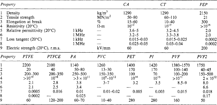
*CA, cellulose acetate. PA, polyamide, PVF. polyvinyl fluoride. PVF2, polyvinylidene fluoride. PTFE, polytetrafluorethylene. PTFCE, polytrifluorochlorocthylene. FEP, fluorinated ethylene propylene. PET, polyethylene terephthalate. CT. cellulose triacetate. PI, polyimide. PVC, polyvinyl chloride (plasticised).
Silicone elastomers: Silicone rubbers or elastomers are a range of heat stable elastic silicone materials used for electrical insulation as sheet, tape, wire and cable coverings, extruded sleevings and mouldings, unsupported, but more extensively as coated glass-fibre cloths, tapes and braided glass sleevings. Such fabric tapes impregnated with a silicone elastomer are available straight or bias cut in thicknesses of 0.07–0.5 mm. Other fabric tapes, coated on one side with partially cured silicone elastomer, are used for taping bars and coils and the curing subsequently completed by baking. The cured taping forms a homogeneous coating having good resistance to moisture, discharges and heat, e.g. for continuous use at about 180°C and up to 250°C for short periods, and possessing high electric strength and low dielectric losses. Most grades of silicone rubbers remain flexible at temperatures down to −60°C and some can be used down to −90°C.
7.7.4.7 Composite sheet insulations
These combine two or more materials, especially varnished cloth, presspapers, vulcanised fibre, plastic films bonded with special adhesives. Particularly widely used have been cellulose fibres combined with polyester or cellulose acetate film, polyester fibre paper combined with polyester film and various combinations of mica, varnished glass fabrics and polyester film. Among the newer developments are combinations of aromatic polyamide paper with polyimide film, giving a material suitable for use at temperatures above 220°C. Another combination is aromatic polyamide paper with polyester film, having good class B performance.
7.7.5 Sleevings, flexible tubings and cords
Tubular sleevings made of cotton, polyester, asbestos, glass, ceramic, quartz, silica, polyamide and other fibres supplied untreated in flat tubular form are suitable for low-voltage insulation of connections of coils, etc. Glass sleeving given a high-temperature treatment before use has the fibres set in place, thus preventing unravelling during assembly. Varnishing of all these sleevings during treatment of the coils is the usual practice.
Similar sleevings may be varnished or treated with resins and polymers before use; these types are known as coated sleevings. Most colours can be produced, thus helping in identification of circuits. The coating materials in general use for cotton and rayon sleevings are natural or synthetic varnishes. For glass fibres, high-temperature polyvinyl chlorides, polyurethanes and silicone elastomers are widely used as well as high-temperature varnishes such as those based on acrylics, polyesters, silicones or polyimide resins. Coatings of fluorinated resins on glass fibres are available.
Flexible tubings can be extruded from most of the materials mentioned in Section 7.7.4.6, but as many of these materials are thermoplastic and also liable to oxidation problems, care is required at temperatures above 90°C.
Other methods of making tubing are by helical winding with adhesives as a bond, when very thin walls (e.g. 0.025 mm) are required or only small quantities are needed. Many of the extruded tubings and some of the helix types can be caused to shrink by applying heat after the tubes have been assembled. Most shrinkage takes place in diameter but there is sometimes a small amount in length. These sleeves are useful for insulating connections and joints, for covering capacitors, resistors, diodes, etc., for colour coding, sealing and moisture proofing. The two main shrinkage processes are: (1) thermoplastics stretched during manufacture, and allowed to cool so that the mechanical strains are frozen in, shrink next time the material is heated; and when certain materials are exposed to high-energy radiation, molecular cross-linking occurs, and they shrink when the temperature is subsequently raised.
Cords for lashing bundles of switchboard wiring, holding leads in position and for tying down coils in machines and transformers, may be made from yarns laid together and twisted or braided, or from narrow woven or slit tape. The trend is away from cellulose materials (linen and hemp) to synthetics, especially glass and polyester fibres. Because of the poor abrasion resistance of glass fibres, glass cords are often pretreated with epoxy or silicone resins or with various polymers. Normally the type of treatment depends on the application.
For high-voltage machines, a useful material is a round cord 3–5 mm diameter comprising a central core of straight polyester fibres surrounded by a braided polyester sheath. This material shrinks slightly on heating, and tightens. For smaller windings, polyester mat can be slit into tapes and several tapes twisted together. Polyester fibre cords of all kinds have the advantage over glass cords that knots can be made without appreciable loss in strength. Glass and polyester bands can be treated after application with varnishes and both have good resistance to abrasion and to mould growth. For rotors straight unidirectional glass-fibre bands pretreated with epoxy, polyester, or acrylic resins are used. These bands must be applied under controlled tension to ensure that the windings are held against centrifugal force. Such bands can be placed safely near voltage carrying parts and (unlike wire bands) are not affected by magnetic fields.
For switchboard wiring, cable harnesses, etc., neat lashings can be made with small-diameter extruded poly-vinylchloride threads. These materials do not burn readily and are obviously well suited for use with PVC insulated switchboard wiring.
7.7.6 Wire coverings
Wires for coils and armature conductors are insulated with lappings of cotton, asbestos, glass fibre and polyamide fibre, all of which are hygroscopic and require treatment with oils, compounds or varnishes, usually after winding. Relevant specifications are BS 1497, 1933, 2479, 2480 and 2776. A recent addition to the range of wire and strip coverings is lapped polyimide film, bonded to itself and to the conductor with FEP polymer: the films are thin and flexible, electrically good and workable at 220°C.
Orthodox oleo-resin (BS 156) and polyvinyl formal and acetal enamels (BS 1844) are tough, resistant to abrasion and to softening by varnishes. Enamelled wires have a better space factor than those with fibre covering.
Some wires are covered in separate operations with synthetic enamels of widely differing characteristics, giving a range of finely balanced properties. The inner coat can be considered as the insulant; the outer coat can give improved resistance to solvents and abrasion, better cut-through resistance, heat-bonding of turns into a solid coil, etc. Wires coated with polyurethane polymers are useful because they can be soldered without first removing the enamel (BS 3188).
For high-temperature working, the performance of PTFE coverings is limited by cold flow of the insulant under mechanical pressure. Silicone resin gives a high-temperature covering but the solvent resistance and mechanical properties are not very good. Better mechanical characteristics are given by polyimide, polyamide imide, polyester imide and polyhydantoin, but these materials are still uncommon.
7.7.7 Moulded and formed compositions, plastics, ceramics, etc
Articles of various shapes, often quite complicated, which cannot readily or economically be matched or built up from sheet, rod or tube materials may be obtained by forming, moulding, coating or casting one of the ‘plastics’ (which are all essentially organic), or a ceramic such as porcelain, or glass or other inorganic materials. The materials can be grouped approximately as follows.
Organic thermoplastic: Examples are: compounds made of natural gums, bitumen, etc., not specially processed; synthetic resin products such as polyvinyl chloride, nylon, polystyrene; cellulose derivatives such as cellulose acetate.
Organic thermosetting: These are, chiefly: cured shellac products including micanite (for simple shapes, e.g. commutator cones); rubber sulphur and similar vulcanisable compositions; compounds made from synthetic resins of the phenolformaldehyde type, urea formaldehyde, silicones, polyesters, alkyds, epoxies and polyurethanes.
Inorganic: The principal materials are listed below.
(1) Asbestos—cement compositions, mainly for high heat resistance, particularly for parts exposed to arcs;
(2) Concrete, cast or moulded, for inductors and switchgear where strength and fire-resistance are needed;
(3) Porcelain, mainly for out-door use and other cases where dust and moisture collect readily, also special grades for high temperatures;
(4) Steatite, for uses similar to those of porcelain;
(5) Special ceramics for radio capacitors, sparking plugs, etc.;
(6) Fire-clay for holding electric heating elements;
(7) Glass for out-door insulators, lamp bulbs, valves and high-frequency insulation;
(8) Mica-glass composition for high-temperature applications requiring good electrical properties, especially at high frequency.
7.7.8 Methods of moulding and forming materials
The principal methods of manufacturing parts from the organic materials are as follows.
Forming of laminated and other sheet materials in open moulds or other forming tools with moderate pressure, the material being made plastic by a suitable liquid or, more usually, by heat. Such forming is generally restricted to relatively simple shapes such as channels, cones, tubes, collars, spools and wrappings. Heat is usually applied during the forming operation, and the material sets either by cooling, heat-treatment in the mould, or subsequent drying, baking, etc. (e.g. vulcanisation).
Moulding under pressure in closed metal moulds (‘compression moulding’), using a powder, dough, treated paper, treated fabric or other form of moulding material and heat treating during or subsequent to moulding.
Injecting material, made plastic by heat or other means, into moulds under pressure and setting by cooling, or heat processing.
Extruding plastic material as for injecting but not into moulds, the shape being determined by the orifice or die through which the material is extruded and the setting being generally due to cooling, but may be followed by a further process such as vulcanisation.
Casting a liquid or molten material into moulds (without pressure) and conversion to a solid condition by cooling or heating (thermosetting materials), or by the action of chemicals with or without heat.
Coating with polymers in powder form, spread on heated metal components by several methods including electrostatic fields or fluidised bed techniques. Thick coatings with good electrical properties can be applied overall. Conversion to the solid is by cooling with thermoplastic materials, or by further heat treatment for thermosetting materials. Some polymers can be applied to surfaces (which need not be metal) in the form of dispersions in a suitable liquid carrier, followed by curing by heating.
Properties of typical organic moulding compounds are listed in Table 7.23.
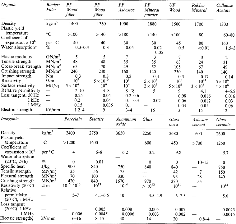
7.7.8.2 Inorganic materials (ceramics, etc.)
The methods used for producing articles from the inorganic materials are, briefly, as follows.
Asbestos-cement compounds: Made from asbestos and other minerals, e.g. powdered silica, mixed wet with lime or Portland cement and moulded cold by compression moulding. After removal from the mould the parts are cured in live steam.
Concrete: The large mouldings for inductors are made of high-grade concrete, made from specially selected Portland cement, sand and aggregate, the wet mixture being poured and ‘puddled’ into suitable moulds and, after preliminary setting, the parts being cured in live steam.
Porcelain: Made from china clay (kaolin), ball clay, quartz and felspar, finely powdered and mixed with water. Small parts (e.g. tumbler switch bases) are made by the dry process (or die pressing), in which a slightly damp mixture is compressed in steel moulds. Many high-voltage parts, particularly large pieces such as transformer bushings, are made by the wet process from a wet plastic mixture, shaped on a potter’s wheel and turned on a lathe. Others, such as overhead line insulators, are made by pouring a creamy mixture into plaster moulds in which partial drying occurs. Parts formed by the foregoing processes are then dried and usually coated with glaze, after which they are fired in a kiln at temperatures such as 1200–1400°C.
Steatite: Consists of powder soapstone (talc) die pressed dry or moulded wet, similar to porcelain, and finally fired at about 1400°C.
Special ceramics: A number of ceramics are made, similar to porcelain and steatite, from such materials as rutile (a form of titanium dioxide)—having low losses and high permittivity, and suitable for high-frequency capacitors—and aluminium oxide, mainly for sparking plugs. A ceramic composed of barium titanate has exceptionally high permittivity.
Fire-clay refractory ceramics: Made from special grades of clay, usually die pressed and fired, somewhat as in the case of porcelain.
Glass: Made from powdered silica mixed with metallic bases (soda or potash) and a flux (e.g. borax). The mixture is fused at temperatures of the order of 1200–1400°C, and the molten mass ‘blown’ into moulds, or forced into moulds under pressure, the parts being removed when cool.
Developments have been made in which the glass instead of remaining in its usual super-cooled liquid state is devitrified, with the result that a fine-grain structure develops and the mechanical properties are much improved. These new materials are known as glass ceramics and can have specially controlled properties. In particular the coefficient of thermal expansion can be selected from high positive to negative values.
Mica glass composition: Produced from powdered mica and glass, heated to a semi-molten condition and moulded in steel moulds by compression or injection at high pressure.
Properties of typical ceramics and other inorganic formed or moulded compositions are summarised in Table 7.23.
7.8 Composite solid/liquid dielectrics
Combinations of solids and liquids are widely used for electrical insulation. The solid normally consists of sheets of paper or of polymer film with an insulating liquid, typically a mineral oil, as the liquid component of the composite. Sometimes a synthetic oil is used instead of a mineral oil, especially when polymer films are used as the solid component. Particular applications of composite insulation are power cables, transformers, bushings and capacitors. The solid provides mechanical separation between the conductors and the liquid gives high electric strength with a low dielectric loss.
7.8.1 Breakdown mechanisms in composite dielectrics
The construction of composite dielectrics usually starts with the solid material in tape form that is wound around one of the conductors. Several layers of tape are used and there is a small gap between adjacent tapes, with the gaps staggered between layers (Figure 7.5).
The most widely used composite insulation system has the spaces between the tapes filled with a mobile insulating liquid. The system that is used in many power engineering applications such as transformers and oil-insulated switchgear is paper and mineral oil. The dielectric constant of paper and mineral oil is very similar, approximately 2.5, but very different from that of air. It follows that if there are air bubbles in the system there is a much higher electric field in the air bubbles than in the rest of the insulation. Bubbles may become trapped in the gaps between the tapes. The air in such bubbles will break down at a much lower applied voltage than the rest of the insulation, producing additional gas and eroding the solid insulation in contact with the bubble perimeter. This can eventually lead to breakdown of the complete insulation structure.
7.8.2 Oil/paper systems
This insulating system is excellent for high electric strength over long periods of time, provided the insulation is free from significant partial discharges. It is therefore essential that gas bubbles are prevented from forming. This is done by applying a vacuum to the insulation to remove dissolved gas where this is possible, and in insulation systems such as high-voltage power cables by applying several atmospheres pressure to inhibit bubble formation.
In laboratory-scale tests it was found that increasing the pressure of the oil from one atmosphere to 14 atm increased the electric stress that could be applied before partial discharges could be detected from 47 kV/mm to 69 kV/mm, or from 60 kV/mm to 90 kV/mm when a thicker oil was used. There is always a problem in relating the results of laboratory investigations to the design of practical apparatus because of the reduction in strength obtained as the volume of the insulation increases. In extreme cases the breakdown strength may be halved by two orders of magnitude increase in volume under stress.
In a series of tests on samples of oil/paper insulation of reasonable size the 50 Hz strength always exceeded 40 kV/mm and the 1/50 μs impulse strength was always greater than 90 kV/mm. The presence of moisture in the paper will give a 40% reduction in breakdown strength when the moisture content is increased from zero to 8%. The impulse strength of oil-impregnated paper increases as the thickness of the paper tapes decreases. In one set of tests the impulse strength was 130 kV/mm for 0.13 mm thick tapes and 160 kV/mm for 0.03 mm thick tapes.
The proven long-life-times of oil/paper systems mean that this insulation is the normal choice for insulating power transformers, cables and power-factor-correction capacitors.
7.9 Irradiation effects
Electrical equipment is being used increasingly in situations where it will be exposed to the effects of nuclear and other types of radiation, often at high energy levels. Such radiation can change the characteristics of many materials and may cause severe deterioration; on the other hand, radiation can have beneficial effects, especially by causing synthetic polymers to cross-link. Particular cases are the irradiation of polyethylene and other thermoplastic materials giving new products with improved properties, especially resistance to heat and mechanical failure; the vulcanisation of rubber; the polymerisation of plastics; the curing of resin and varnish films and the manufacture of heat-shrinkable films and sleevings.
7.9.1 Type of radiation
The more common forms of radiation encountered are: neutron and γ from nuclear reactors, neutron and γ from isotopes and electrons and X-rays from particle accelerators. The unit of absorbed radiation is the rad (= 100 erg/g) or the megarad (= 108 erg/g of material). The megarad is equivalent to 10 kJ/kg.
Although the effects of radiation on materials are cumulative and, therefore, dependent on the total dose, the dose rate (generally expressed as megarads per hour) may have some further effect. This point must be considered when experimental work is being carried out. Fortunately, it has been found that changes in most materials due to irradiation are practically independent of the type of radiation encountered. Hence, various sources of irradiation may be used for experimental work and those normally employed are:
(1) ‘hot’ fuel elements and other parts of nuclear reactors;
(2) radioactive isotopes (e.g. cobalt 60);
The most convenient is the linear accelerator, in which a small-diameter beam can be made to scan the parts to be irradiated with uniformity of dosage. The physical conditions—temperature, ambient atmosphere (air, carbon dioxide, nitrogen, etc.), and humidity—must be carefully selected and controlled.
7.9.2 Irradiation effects
The effects of radiation are usually assessed in the first place by visual examination, as many materials discolour, crack, disintegrate or melt, while flexible or soft materials may become hard and brittle.
More advanced work relies on the determination of changes in measured properties after certain periods of irradiation. Results of tests on unirradiated samples are compared with those on similar samples after subjection to known energies for different times. Non-destructive tests (loss tangent, permittivity, resistivity, changes in weight and changes in dimensions) are particularly useful because they can be repeated on the same specimen as a function of the total dose. Other tests used to determine the effects of irradiation are electric strength; tensile, shear and impact strength; elongation; hardness; flexibility; and water absorption.
In general, organic insulating materials deteriorate mechanically and electrically as the result of irradiation, the mechanical properties usually being impaired at a greater rate than electrical ones. These results are mainly due to chemical changes which occur in the materials consequent upon certain rearrangements of their molecular structure, usually with the evolution of one or more gases, such as methane, carbon monoxide, carbon dioxide or hydrogen. The probable life-dose for typical insulating materials is given in Table 7.24. The dose figure is that at which marked deterioration is observable, there is a 50% reduction in mechanical and electric strength, or some similar factor. The life-dose is approximate: it depends on the actual formulation of the material and irradiation conditions such as dose-rate and ambients.
Table 7.24
Radiation resistance of organic insulating materials: probable useful-life dose
| Material | Mrad |
| Gases | |
| Sulphur hexafluoride | 5000 |
| Difluorodichloromethane | 1000 |
| Trifluoromonochloroethylene | 500 |
| Perfluoropropylene | 100 |
| Moulded or laminated plastics (filled) | |
| Diphenyl silicone/glass | 10 000 |
| Mineral-filled epoxyphenolics | 10 000 |
| Mineral-filled phenolics | 4000 |
| Epoxy/glass cloth | 4000 |
| Cellulose-filled phenolics | 1000 |
| Cellulose-filled urea formaldehyde | 1000 |
| Elastomers | |
| Polyvinyl chloride (plasticised) | 500 |
| Polyurethane rubber | 400 |
| Butadiene styrene + antiradiant | 300 |
| Phenylmethyl silicone | 200 |
| Polychloroprene | 150 |
| Natural rubber | 150 |
| Acrylonitrile | 100 |
| Polysulphide | 80 |
| Dimethylsilicone | 30 |
| Polyisobutylene | 20 |
| liquids | |
| Polyphenyls | 5000 |
| Radiation-resistant petroleum oil | 2000 |
| Transformer oil (naphthenic) | 500 |
| Transformer oil (paraffinic) | 500 |
| Silicone oil | 200 |
| Pyorchlor | 100 |
| Resins, bitumens, etc. (unfilled) | 5000 |
| Diphenylsilicone | 5000 |
| Polyvinyl carbazole | 4000 |
| Polyvinyl carbazole | 2000 |
| Bituminous compounds | 2000 |
| Nylon | 2000 |
| Polyethylene | 2000 |
| High-impact polystyrene | 2000 |
| Polyurethane | 1000 |
| Alkyd resins | 500 |
| Phenol formaldehyde resins | 500 |
| Polyethylene terephthalate | 500 |
| Cellulose nitrate | 100 |
| Cellulose butyrate | 50 |
| Cellulose acctate | 50 |
| Methylmethacrylate | 50 |
| Polytetrafluoroethylene | 5000 |
7.9.2.1 Gases
The spark-gap breakdown voltage of air is reduced by about 20% under intense nuclear radiation. A gas having good radiation stability is sulphur hexafluoride (SF6), whereas halogenated hydrocarbons slowly polymerise with evolution of corrosive products, and other gases, such as perfluoropropylene, polymerise rapidly to form liquids when irradiated.
7.9.2.2 Liquids
The viscosity of hydrocarbon oils increases and most liquid dielectrics polymerise when irradiated, the electrical properties being lowered considerably. Gases are usually evolved by liquids during irradiation and can create difficulties due to increase of pressure in containers of capacitors, transformers, etc. Silicone oils polymerise to form elastomers, those of high molecular weight yielding elastomers of low tensile strength, but the solids produced from the low molecular weight (e.g. 300–20000) oils crumble on handling.
7.9.2.3 Semi-fluid and fusible materials
Silicone compounds made from fluids with mineral fillers react to irradiation in the same manner as the fluids; they rapidly harden and then gel. Petroleum greases are affected similarly. Dimethyl silicone fluids of low viscosity are to be preferred for use where doses do not exceed about 100 Mrad.
7.9.2.4 Organic solids
Most of the organic solid insulating materials in general use are synthetic resins or are based upon such resins and similar plastics. The performance of the materials in the form in which they are used under irradiation conditions depends largely upon the resistance of the basic materials to the effects of radiation. Cellulose derivatives, such as cellulose acetate, have poor resistance, mechanical deterioration being rapid; hence lacquers, adhesives and moulded or extruded parts made from them also deteriorate rapidly under irradiation. On the other hand, diphenyl silicone and products made from this resin, have relatively good resistance. The combination of mineral materials, whether as powdered or fibrous fillers or as sheet reinforcement (e.g. woven glass cloth), with the organic base materials usually results in products having superior radiation resistance.
7.9.2.5 Synthetic resins: thermoplastic
Of the thermoplastic synthetic resins polystyrene is one of the most stable. Styrene copolymers are generally poorer in resistance to effects of radiation, and high-impact-strength polystyrene loses some of its impact strength when irradiated. A good deal of work has been done on the effects of irradiating polyethylene, the principal change being the elimination of its melting point due to cross-linkage: this can be beneficial. Some increase in tensile strength occurs at first but, with continued irradiation at high dosages, the tensile strength decreases and the material ultimately becomes brittle and cheesy. The high-density varieties are slightly better. Nylon behaves somewhat similarly when irradiated, cross-linkage occurring with consequent increase in tensile strength in the case of sheet, but rapid reduction of strength occurs in nylon fibres, with decrease of elongation and impact strength.
Of the vinyl polymers and copolymers, polyvinyl carbazole has good resistance to radiation; polyvinyl chloride (PVC) has radiation resistance equivalent to that of polyethylene but liberates hydrogen chloride when irradiated; vinyl chloride acetate has a lower radiation resistance than PVC, softening and turning black at low dosages.
Irradiation of polyethylene terephthalate in fibrous form causes rapid loss in strength, and the films become brittle and darken. Cellulose plastics such as cellulose acetate deteriorate mechanically to a serious extent by low dosages, but electrical properties of the latter are not appreciably affected. Acrylic resins also have comparatively low radiation resistance.
The thermoplastic resins most seriously affected by radiation are the fluoroethylene polymers such as polytetrafluoroethylene and monochlorotrifluoroethylene, the latter being superior. Decrease of tensile strength and elongation of these is rapid and they become very brittle with only moderate dosages.
7.9.2.6 Synthetic resins: thermosetting
Of the amino resins, the melamine formaldehyde type is slightly superior to the urea formaldehyde, but with cellulose fillers both deteriorate rapidly and become brittle when irradiated. The radiation resistance of epoxy resins is above the average for plastics but it depends largely on the hardener used. Epoxyphenolic resins are better than ordinary epoxies and phenolics for radiation resistance. Phenolic and polyester resins without fillers have low resistance but this is increased considerably by the addition of fillers, especially minerals such as asbestos.
Silicone resins are more resistant to radiation than silicone fluids and elastomers and do not rapidly deteriorate physically, the major electrical properties of most resins being maintained even after subjection to high dosage.
7.9.2.7 Solid materials: inorganic
In general, inorganic materials are much more resistant than organic materials to irradiation. The principal effects are to cause colour changes and to induce conductivity in glasses, ceramics, fused silica and mica, followed by disintegration of natural mica irradiated by high dosages at elevated temperatures (e.g. 150°C). Synthetic mica seems to be more resistant than the natural form to mechanical and electrical degradation. Built-up mica products made from flake mica or reconstituted mica paper are affected according to the bonding medium—which is usually organic. Wires insulated with swaged magnesium oxide have shown high resistance to radiation at a temperature of 815°C.
7.10 Fundamentals of dielectric theory
An ideal dielectric is a material or medium which has no free electrons so that no conduction can take place. It is an ideal insulator. Electrically it can be represented as a pure capacitor
Real dielectrics, however, have some free electrons but much less compared with conductors. Their equivalent circuit can be represented by an RC parallel circuit.
7.10.2 Types of dielectrics
Dielectrics can have three forms: gas, liquid and solid.
In gases, the atoms/molecules do not interact but can contain free electrons which are responsible for the conduction process. Conduction mechanisms due to positive and negative ions as well as charged molecules are also found in some gases.
In liquids dielectrics, there is some interaction between molecules, and they are also known to contain impurities in real applications. This makes the conduction process essentially ionic in nature with the addition of contributions due to charged particles.
Solid dielectrics have more complex conduction mechanisms (such as thermal, tunnelling, hoping) governed by free electrons, holes and ions.
Solid dielectrics can be either:
(a) Glasses: are amorphous materials which have no three dimensional atomic ordering over distances greater than 2 nm (atoms are tenths of nm across).
(b) Crystals: these have long range ordering which could lead to a single crystal if the ordering is consistent throughout the solid material.
In general, no solid or liquid is completely structureless. Ionic solids do not form glasses but covalent solids form glasses (e.g. polymers) e.g. MgO is an ionic solid (non glass) and SiO2 is a covalent solid (glass).
7.10.3 Polarisation in dielectrics
When an insulating material is subjected to an electric field, a limited displacement of charge takes place at the atomic, molecular and bulk material levels. This charge displacement is known as polarisation.
(a) Electronic polarisation: in atoms, positive ions are surrounded by electron clouds. Since the electrons are very light, they respond rapidly to the action of an applied electric field. Figure 7.6 shows a schematic of an atom being polarised due to the action of the field E0.
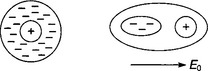
(b) Molecular polarisation: within a molecule, the ionic bond is deformed when an electric field is applied resulting in increase of the dipole moment of the lattice:
Molecular polarisation can be:
(i) Simple ionic where a simple separation of centre takes place.
(ii) Distorted ionic takes place when large ions are distorted by other close ions in addition to the simple ionic polarisation.
(c) Orientational polarisation: in liquids and gases, whole molecules move into line with the acting electric field. Under weak static fields, the alignment is usually not complete. In solids, interfacial polarisation occurs at electrodes and at crystallites interfaces. In addition, in the presence of an interface with materials of different electrical properties (permittivity and conductivity), space charge polarisation occurs. Figure 7.7 shows the various scenarios of orientational polarisation.
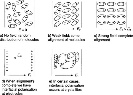
7.10.4 Quantification of dielectric polarisation
For a vacuum-filled parallel-plate capacitor, the surface charge density Q0 is defined as Q0 = ε0 V/d where V is the applied voltage, d the separation distance between plates, and ε0 relative permittivity of free space (ε0 = 8.854 pF/m).
If the vacuum insulating medium is replaced by a dielectric material of relative permittivity εr, the new surface charge density will be Qds = ε0εr V/d.
Thus, resulting in an increase of surface density ΔQs = Qds − Q0 = (εr-1)ε0 V/d.
This quantity is known as the dielectric polarisation P. In this case, the expression can be written as P = (εr − 1)ε0V/d = (εr-1)ε0E = Dd−D0.
With Dd is the electric flux density in the dielectric case. D0 is the electric flux density in the vacuum case.
7.10.5 Properties of dielectric materials
Dielectrics can be grouped according to their structure and the way they react to the action of an electric field.
(a) Non-polar dielectrics: These consist of molecules that do not possess a permanent dipole moment, they are known as simple dielectrics. When an electric field is applied to simple dielectrics, it induces dipoles and orients them in the direction of the field.
(b) Polar dielectrics: If a material has molecules with permanent electric dipole moments, in the absence of an external electric field, then it is called a polar dielectric e.g. Water and NaCl. Within these materials, the individual molecular dipoles are usually randomly oriented due to thermal agitation. The application of an external electric field will result in the alignment of the individual dipoles in the direction of the field. In general, polar dielectrics have low values of relative permittivity and only small concentrations of permanent dipoles. Table 7.25 gives examples of some polar and non-polar dielectrics.
Table 7.25
Examples of polar and non-polar dielectrics
| Dielectric type | Examples | Relative permittivity |
| Non-polar | Transformer oil | 2 |
| Mildly polar | Chlorinated diphenyl | 6 |
| Strongly polar | Nitrobenzene | ≥20 |
| Polypropylene carbonate | ||
| Water | ||
| Ethanol | ||
| Hydrogen cyanide |
(c) Paraelectric dielectrics: By contrast to simple dielectrics and polar dielectrics, paraelectrics contain a strong dipole in each unit cell with relative permittivity values more than 20 and up to 10000.
(d) Ferroelectric dielectrics: By analogy to ferromagnetism, ferroelectrics contains domains (of about 1 μm) where permanent dipoles are oriented in the same direction. When an external electric field is applied to a ferroelectric material, the domains are aligned in the direction of the field. However, they are known to exhibit non-linear polarisation with applied field. Ferroelectrics have a relative permittivity, which increases with temperature until the ‘Curie temperature’ after which the permittivity decreases, and the domains cease to exist. The material becomes then paraelectric (see typical plot in Figure 7.8). Ferroelectrics exhibit hysteresis of polarisation as a function of the applied electric field (see typical curves on Figure 7.9). Therefore, the permittivity of the ferroelectric must be quoted for a given field value, E, a temperature T, and the ‘history’ of the material. Table 7.26 gives examples of some ferroelectric materials.
Table 7.26
Examples of ferroelectric materials
| Ferroelectric material | Symbol | Curie temperature (°C) |
| Potassium dihydrogen phosphate | KH2PO4 | −151 |
| Lead titanate | PbTiO3 | 487 |
| Barium titanate | BaTiO3 | 10 and 120 |
| Cadmium titanate | CdTiO3 | −210 |
| Lead niobate | PbNb2O6 | 570 |

(e) Piezoelectricity: When a ferroelectric material is subjected to an electric field at paraelectric temperatures (see Figure 7.8 and Table 7.26) and then cooled, the domains in the material will align permanently. Mechanical shearing stress when applied to such materials can cause charge displacement, known as piezoelectricity. This property is also found in most crystals having an anisotropic structure e.g. quartz (simple dielectric which has no domains).
(f) Electrets: Any dielectric can contain electric charges at atomic or molecular level that can be oriented by an external electric field. If after cooling, the charges are immobilised, the dielectric will behave as an electrical equivalent of a permanent magnet. This is known as an electret (thermoelectrets in this case). An electret loses its volume charge exponentially but with a very large time constant (order of 100 years). Standard capacitors have time constants from few seconds up to six months (e.g. polystyrene).
7.10.6 Example of ferroelectric material: Barium titanate and its applications
Barium titanate is one of the most important ferroelectrics. It is formed from the reaction of a mixture of BaCO3 and TiO2 heated at 1250°C. The product is powdered and then worked by means of common ceramic techniques. Admixtures of other oxides are employed to modify the dependence of permittivity on temperature. Its high permittivity is exploited in ceramic capacitors for the range 500–10000 pF for electronic equipment. Its piezoelectric property is used in transducer effect since it can be fabricated in a variety of complex shapes. The hysteresis in polarisation is used in timing control or carrier-frequency modulation of a voltage control.
7.10.7 Frequency response of dielectrics
Most materials are polarisable in several ways, producing complex frequency dependence. At the highest frequencies, only the electronic polarisation will ‘keep up’ with the applied field. At frequencies where permittivity varies rapidly, there is a peak in the dielectric loss. Figures 7.10 and 7.11 show typical variations of permittivity and loss angle with frequency.


7.11 Polymeric insulation for high voltage outdoor applications
Traditional insulators are made of ceramic, either porcelain or glass. The design of these insulators for high voltage applications evolved from telegraph wire experience. These insulators are known to perform reliably in service for several decades. However, their bulky nature, poor pollution performance due to hydrophilic surfaces and susceptibility to vandalism raised a need for better materials.
Non-ceramic insulators (NCI), also commonly known as polymeric or composite insulators, are made of a compound of materials having one of several polymers as a base. Two main materials have been used extensively on outdoor high voltages power systems: silicone rubber and Ethylene propylene diene monomer (EPDM). Their combination (EPS) has been proposed to solve particular problems of surface properties and material strength. The main advantages of these materials are their light weight (since the insulator is made from a fibre rod with a polymeric outer sheath) and more importantly their surface hydrophobicity which inhibits the formation of continuous wet paths along the insulator surface. This is particularly advantageous under pollution condition when outdoor insulators suffer from dry-bands followed by localised discharges across the dry bands.
Room temperature vulcanised (RTV) coating is used to enhance porcelain insulators pollution performance by spraying/applying a thin layer of silicone rubber on the porcelain surface giving it a hydrophobic surface similar to that of silicone rubber insulators. RTV coatings contain typically 5% (by mass) cyclic LMW polydimethyl siloxanes.
IEC 1109:1992 Standard describes acceptance test procedures for composite insulators and IEC 507:1991 specifies artificial pollution tests procedures for high voltage insulators to be used on a.c. systems. However, these latter procedures are particularly suited for porcelain and glass insulators. At present, no standard procedure exists specifically for polymeric insulators. One difficulty is related to surface pollution because the hydrophobicity of polymeric insulators makes the conventional technique not suitable. Various methods have been suggested to obtain a uniform and repeatable pollution layer on polymeric surfaces. These include surface abrasion, kaolin spraying, multiple layer spraying and the use of small quantities of wetting agents, such as Triton X-100 as used in BS 5604:1986 (same as IEC 587:1984). International Standard IEC815:1986 gives guidance on the selection of insulators for high voltage applications taking into account the insulator shape and pollution severity.
7.11.2 Hydrophobicity loss and recovery
Extensive laboratory tests and field experience have shown that these materials can lose their hydrophobicity following a number of individual stresses or their combination. In particular, discharge activity on the insulator surface is found to reduce the hydrophobicity significantly. However, silicone rubber is found to recover its hydrophobicity after a certain time (which is still not well quantified) without the damaging stress. This process of recovery is thought to be due to the diffusion to the surface of low molecular weight (LMW) molecules and/or the changes in orientation of the methyl groups of the polymer.
7.11.3 Degradation ageing factors of polymeric insulator surfaces
Despite their excellent pollution performance, polymeric insulators are found to experience faster degradation on their surface compared with conventional insulators. Although such degradation depends on insulator material and design, a number of factors have been identified as affecting the surface properties of polymeric insulators. Some of these are described in the following processes.
7.11.3.1 Electrical process
The electric field distribution along a high voltage insulator unit is not uniform with the highest field regions located at the end terminals. In addition, the regions around the cores have higher electric fields than the shed areas. Under operating service conditions, the insulators are subjected to pollution that modifies the field distribution, reducing the magnitude at the end terminals. However, the wetting process is also non-uniform. The regions at the end terminals (especially at the top end) will wet more and at a faster rate than the regions under the sheds. Such combination of slow wetting and high field magnitudes encourages the initiation of discharges in these ‘under-shed’ core regions. With continuous intense discharging, the surface loses its hydrophobic properties. Furthermore, the discharging process generates ozone and nitrogen oxides which, when combined with water, produce nitrous and nitric acids. These acids attack the end fittings and make the polymer surface brittle forming a crazed pattern which can lead to splitting of the polymer sheath.
Surface currents on polluted insulators combined with the dry band discharging lead to tracking and erosion of the polymeric surface. Tracking and erosion resistance is improved by adding Alumina Trihydrate (ATH) as a filler to the polymer. After ageing, insulators with such materials exhibit a chalky white appearance caused by the diffusion of the ATH from the bulk to the surface.
7.11.3.2 Mechanical process
Direct mechanical stress on insulators can be tensile, compressive or cantilever loading. These stresses can lead to insulator failure by damaging the fibre reinforced plastic (FRP) core. Mechanical stresses usually affect the insulator in combination with other stresses.
Indirect mechanical stress is the form of surface tears caused by the release of stresses trapped during the manufacturing process. This provides arcing regions which would lead to tracking and erosion. Formation of fissures is also possible due to vibrations and the existence of material interfaces in the insulator unit.
Brittle fracture of the FRP rod has been observed under service conditions with insulator mechanical loads below the specified load. Various causes were suggested including faults from the manufacturing process, and water ingress combined with mechanical stress which transports hydrogen ions in solutions with a pH value of 3 or 4.
7.11.3.3 UV radiation
Outdoor insulators are exposed to sunlight, hence, ultraviolet (UV) radiation. UV radiation causes photo-oxidation and scission of molecular bonds in polymeric materials. Photo-oxidation is caused by ionisation of the surface molecules and attraction of the oxygen when the photon energy is sufficient. If the energy of the photon is higher than that of the bonds between the molecules or the polymer chains in the backbone of a single polymer, scission occurs.
Silicone rubber has a high resistance to damage by UV radiation because the siloxane (Si–O) bonds are of high energy. However, the hydrocarbon groups in the polymer can be damaged. UV resistance is usually increased by the use of carbon-based fillers which have the disadvantage of affecting the insulating properties of the material.
Intense UV exposure can lead to reduction of the silicone polymer on the surface of the material accompanied by an increase of the filler. Such surface depolymerisation was found to accelerate loss of hydrophobicity and increase of surface leakage current.
7.11.3.4 Chemical processes
Chemical attack occurs due to pollution products and following discharge activity on the insulator surface. Examination of field-aged insulators has found formation of uniform thin pollution layers on the surface. Sea or coastal pollution contains salts, while inland pollution comprises dust, industrial particles and agricultural fertilizers. When wetted, these pollution products react with the polymer under the action of the applied field. In tropical climates, micro-organism growth was found on insulator surfaces which was found to enhance the surface leakage current. The current increase warms the insulator surface, which further encourages the growth of the bacteria population. Partial arcs destroy the organisms but leave biological remains in the form of a slimy surface.
7.11.3.5 Water ingress processes
Water ingress in polymeric insulator occurs in three ways a) ingress through poor seals at end fittings, b) ingress through surface defects/damages, or c) through absorption of water into the polymeric material itself.
Corrosive chemicals and/or ionisable contaminants carried by the water affect the mechanical strength of the FRP rod and this is known to cause brittle fracture.
Water absorption causes depolymerisation as well as polarisation of the interfaces between the polymer and the fillers. More importantly, it increases the permittivity and loss tangent while it decreases the dielectric strength. As a consequence, heavy erosion and shed puncture can occur following moisture ingress.