
Health and Safety
24.1 The scope of electrical safety considerations
It has often been said that electricity poses hazards quite unlike any other hazard which commonly presents itself to persons in the workplace and elsewhere, including in the home. Electricity has the capacity to kill and injure through electric shock, through burns and through fires started electrically. Other dangers involving the use of electricity may be found in the aberrant and dangerous actions of electrically controlled machinery and the maloperation of plant control systems based on relay and/or computer logic circuitry.
Electrical accidents, unlike most other industrial accidents, are more likely to involve professional and supervisory staff. In some situations they may be at greater risk than most other staff particularly where electrical power distribution circuits are being switched or maintained. In a typical year1 47% of electrical accidents involved electrically skilled persons and out of a total of 805 electrical accidents 57 were to supervisory and testing staff. Electricity has a stealth and power which are often disregarded even by electrical engineers and other electrically trained persons.
All those who are involved in potentially hazardous work with electrical equipment, such as the testing of high-voltage apparatus or supervising the alterations to circuits in an important substation, have statutory legal duties of which they must be aware. They must conduct their work in accordance with the statutory requirements and ensure that those under their control also conduct their work properly. In the UK these are criminal law obligations, quite distinct from liability for negligence in civil law which may also arise if matters go wrong. All engineers should make themselves aware of the statutory requirements and of the potential liabilities which they run as persons with responsibilities for the health and safety of themselves and others.
Nearly all electrical accidents, even those at low voltages (e.g. 230 V a.c.) are potentially fatal and the causes and remedies are now almost completely understood. There is no shortage of guidance on the various hazards presented by electricity and on the statutory requirements relating to these. In Great Britain much of this guidance is published by the Health and Safety Executive (HSE) which has the main responsibilities for safety and health legislation arising from ‘work’ activities and the enforcement of this law.
Other considerations in the context of health and safety of which electrical professionals should be aware are the various directives of the European Union (EU), such as the ‘Low Voltage Directive’ 73/23 EEC, the ‘Machinery Directive’ 98/37/EC and the ‘ATEX Directive’ 94/9/EC which have a safety content. A raft of EU directives and domestic implementing legislation covers the generality of health and safety on hazards other than from electricity but these are outside the scope of this discussion. For further details on these refer to the HSE, DTI and other sources listed below, some of which are available on-line through their Internet websites.
24.1.1.1 Control of staff and permits to work
In the context of persons ‘at work’, the emphasis in all work on electrical equipment must be that this normally be conducted with the equipment de-energised and made safe, i.e. ‘dead’ working. ‘Live’ working is a specialised activity and is permitted only in exceptional circumstances. No one should be allowed to do anything which carries electrical risks without the provision of adequate precautions to reduce the risk of injury to a minimum. The persons must also have the necessary skill, experience, technical knowledge and other resources to do the work safely. Managers and supervisors must therefore satisfy themselves that no one is asked to do any work for which they are not competent and specifically authorised by the management. Such authorisation is usually through a formal process of instruction and examination in company procedures.
Particular care must be taken with students, trainees and apprentices. Apprentices are often expected to learn to carry out potentially dangerous jobs during their apprenticeship but they must be carefully supervised.
When work must be done where electrical danger may be present, and some electrical work (particularly in testing and maintenance) cannot be made absolutely safe, instructions must be precise and unambiguous. Procedures must be observed correctly. All necessary and relevant technical manuals and drawings etc. should be available.
Much ‘dead’ work is carried out under ‘permit to work’, particularly in the electricity generation, transmission and distribution industries which have an established and universal system of safety rules (with local variations for each electricity company). Permits usually relate to equipment which has been made dead. Permits must be issued and cancelled in an orderly and clearly defined manner. A full record must be kept so that it is possible, at any time, to find out what is going on, who is involved or at risk, and what precautions have been taken.
The permit must state clearly and fully to whom it is issued (this person should be present at all times and is responsible for what happens), name those persons who may be present in the working area, and state what special precautions have been taken to prevent danger. The safe and unsafe areas must be stated on the permit, preferably supported by means of a diagram, and clearly indicated on the actual work site by means of flags and barriers etc. The work to be done must be clearly described and no other work may be carried out because this could entail risks not contemplated by the person issuing the permit, who may not have taken the extra precautions necessary.
At the end of the work there must be a clearly defined procedure for handing over. A check must be made that all persons have been withdrawn from the work site and the result recorded. Before the permit is cancelled, a statement must be recorded (preferably on the back of the cancelled permit and also in the log book, where one has been kept) of what work has been done, what has not been done, and what steps have been taken to make the site ready for resumption of normal operations. Until a permit has been cancelled the person to whom it was issued remains responsible for the conduct of any work on that equipment.
If the work lasts for more than one shift there must be an appropriate method of hand over to ensure that the new shift supervisor is familiar with the state of the work and the terms of the permit. It is often preferable to cancel the first permit and to issue a new one. Sometimes the person with the authority to issue permits takes charge of the work, in which case they should issue a permit to themselves.
Experience has shown that all this detailed procedure is essential. The routine not only ensures that there is a record which will help to identify the cause of any mistake, but the action of writing down all the details helps to prevent anything being overlooked. Since all key persons involved must sign all of the records and statements the routine reinforces the understanding of the various instructions and helps to ensure that these instructions have been read and understood.
Some testing and research work presents its own hazards. As the conditions may vary greatly it is difficult to lay down general rules and safety depends largely on the skill of the staff. For certain work earth-free areas with power supplies isolated from earth are provided and used in conjunction with other precautions such as the use of unearthed tools (such as very low voltage soldering irons).
Routine high-voltage testing is normally carried out in enclosures with interlocked doors and provision for supervision from the outside. Where unskilled or semiskilled persons do routine testing on a production line arrangements must be made, by guards and interlocks for example, to ensure that they are not exposed to live conductors operating above 25 volts a.c. or 60 volts (smooth) d.c. thus eliminating likely shock risks.
24.1.1.2 Non-electrical causes
Many electrical accidents are the result of mechanical and other causes. Examples of these causes are mechanical stresses, thermal shock on insulators, resonant vibrations of conductors leading to fractures, low-temperature brittleness or corrosion fatigue. Too often however the causes are banal, such as a badly constructed joint or a loose connection. To deal with such troubles it is necessary to have more than a narrow interest in electrical matters. Much of electrical safety engineering requires a good understanding of mechanical engineering and the strength of materials because many accidents involving electricity are due to a poor understanding of the properties of materials. However, electrical accidents are also largely due to the uses and abuses to which otherwise sound equipment is subjected.
A further dimension in electrical accidents is that the stealthy power of electricity is inadequately understood. Even many electrical engineers, perhaps because their training and experience may not have exposed them to the destructive capabilities of electricity, can be disrespectful of this power. For example, very few engineers actually get to witness a substantial power arcing fault and few get to examine the after effects of a serious electrical fire, explosion, arcing fault or other dangerous occurrence. However, those that do usually find themselves surprised and acquire a deeper respect for electricity.
The official report on the enquiry into the disastrous explosion and fire at Flixborough in 1974 (which featured the mechanical failure of a temporary modification to the naphtha cracker) stated that engineers should have academic and practical training in all branches of engineering outside their speciality which may affect their work. This might seem to imply the need for training in the many fields of expertise of only tangential interest to one’s own discipline but in reality one person can seldom expect to understand every aspect of a particular plant, apparatus or process on which they have to work. There is often a need to draw upon shared expertise with colleagues or even to seek outside help in order to deal properly with certain problems. The key point is that the engineer should recognise his or her limitations. If the competence, experience or expertise are inadequate to the circumstances then help should be sought.
24.1.1.3 Design standards
The integrity of much electrical equipment is now greatly assured through a comprehensive range of published Standards which have been established nationally and internationally through the various consensus seeking Standards organisations such as the British Standards Institution (BSI), the European Electrical Standards body, CENELEC, and the International Electrical Standards body, IEC. The work of these bodies has contributed hugely to the safety and integrity of much electrical equipment over many decades. However, safe use of equipment also relies on the correct interpretation of the scope of the Standards applying to that equipment. A Standard is only one link in a chain.
It is worth remembering too that with few exceptions Standards are written in a consensus seeking forum comprising representatives from the various interested groups. These groups usually comprise manufacturers, or their trade associations, government bodies, test houses and inspection agencies and, to a lesser extent, representatives of the actual users of the equipment.
British Standards have fulfilled a useful role over decades but it must now be recognised that almost all Standards work is conducted in an international forum with the needs, hopes, customs and expectations of domestic users being subject to a large measure of international influence. This internationalisation is not always welcomed by some but it is inevitable.
Traditionally British Standards have been drawn up in a manner which recognise some basic principles of electrical engineering safety. Some of these are:
• The insulation of conductors should be unable to come into contact with moving parts.
• Earthing terminals should be adequately locked against loosening. These terminals shall not serve for any other purpose, e.g. for securing parts of the case.
• Electrical connections should be so designed that the contact pressure is not transmitted through insulating material other than ceramic or other materials not subject to shrinkage or deterioration.
• Soldered connections should be so designed that they keep the conductors in position if the conductor breaks at the point of connection
In many situations it is important that fingers, steel rules etc. cannot touch live or moving parts of electrical equipment and a number of probes have been devised to test and prevent this, including a standard test finger which is hinged to mimic the reach of the fingers on a human hand.
24.1.1.4 Investigations
Most engineers will, at some time, have to investigate an accident or plant failure. The purpose of an investigation is to ascertain the facts and initiate any necessary action. The first requirement is to make sure that all the relevant information has been obtained and that it is correct. Persons who have witnessed a severe accident are often shocked and emotionally distressed. They may be quite unable to distinguish between what they have seen and what they think they ought to have seen, or perhaps what they have imagined when trying to rationalise their confused memories. Some people may also have good reason for wanting to mislead while others quite genuinely lose all memory of events immediately leading up to the accident. Sometimes however, the person injured is less upset and a better witness than the on-lookers.
It is important to remember that the impossible does not happen, and the improbable only happens occasionally. Accidents are usually the result of several contributory factors coinciding whereas a machinery design or a procedure is likely to have been based on only one factor occurring at a time.
It is important to examine the debris and all equipment very carefully after a failure and be critical of stock wiring diagrams; they frequently contain mistakes or refer to the wrong apparatus. It is common for modifications not to have been recorded properly.
Having determined how an accident has happened, it is important to find out why. This usually involves the highly complex issues of interfaces between humans and machines and the management of staff. Temperament is important in some jobs and boredom, stress, overwork, rivalries, physical and mental health and all human emotions play a role in the workplace. An example of the importance of temperament matching the task is that of a plant control engineer who may have long periods of dull routine punctuated by occasional emergencies when quick and correct decisions are necessary. It is a job which suits only certain types and where the consequences of error can be extremely serious.
24.1.1.5 Written reports of accidents
If an accident report is muddled or unconvincing, the time spent on the investigation will have been wasted. A report should err slightly on the long side rather than be obscure but it is preferable that it conveys the main points lucidly and concisely.
Reports that recommend action by managers or directors will fail if the reports are incomprehensible to these people. Good report writing is an art which usually requires much concentration and practice. Some pointers are:
• Careful preparation pays dividends. Well chosen headings and a planned layout are essential. The argument needs to be thought out clearly and arranged in a logical sequence so that, as far as possible, each paragraph follows naturally from the one before. If this thinking is done thoroughly the actual writing of the report will take on a natural flow which will be limited only by the speed at which one can write or type.
• Each sentence should carry the argument forward starting in such a way that the reader half expects what is to follow.
• Care is needed with punctuation. For example, commas should not be used excessively or in order to divide up a sentence like the brackets in an algebraic equation.
• Avoid long and involved sentences. Economy of words is a virtue. Short words are preferable to long ones, common words preferable to obscure ones. Words should express exactly the concept or message which must be conveyed. A Thesaurus can help identify the best words for the purpose. All doubted meanings should be checked with a good dictionary; it is really astonishing the diversity of understanding which even the commonest words have among most people (e.g. acute/chronic). Avoid technical jargon as far as reasonably possible. It often has surprisingly limited currency.
• Put all the supporting documentation into appendices in order to keep the main text succinct. The main text of the report should ‘stand alone’, i.e. it should be a readable narrative with a clear and logical progression of its own without the need to refer to the appendices.
• Check spelling. (Computers can now do much of this automatically, although one needs to be aware of international differences.)
Some relevant publications on this topic are given below.3
24.1.2 Recent developments
An important development in recent years has been in the application of ‘solid-state’ devices and computers to electrical control. Even in the traditional areas of electrical power generation, transmission and distribution the use of microelectronics is now commonplace throughout all modern networks, from control rooms to protection relays. The reliability of most conventional hardware is now well established and it is possible to compute the probable ‘life before failure’ of most items of equipment. This, however, does not help to trace those defective components which operate only in emergency and could have remained unused and defective but undetected for years. It is virtually impossible to detect all weak links with certainty.
The weaknesses of the software in a computer system are even more difficult to detect. The embedded nature of software faults puts this type of fault into a special and sinister class of its own. However, the usefulness of computers makes it imperative that this weakness be understood and accommodated where computers are used in safety related applications. An enormous quantity of work has been done to get to grips with this problem and is the subject of comprehensive guidance and Standards.4
An associated development has been the increasing use of fibre optics for the transmission of information and instructions and the subsequent development of ‘optical’ switches and relays. These reduce fire and explosion hazards. They also eliminate the disturbance of control systems and telecommunications by electrostatic and magnetic induction and by gradients in the ground and structures caused by power faults and lightning discharges.
Another important development has been the realisation of the seriousness of the toxic hazards arising from the use of polychlorinated biphenols either through leakage into the environment or through the production of toxins arising from fires. These coolants were used increasingly from the mid-1950s to about 1975 to replace mineral oil in power transformers and capacitors to reduce the danger from fire and explosions. Oil-less, otherwise referred to as ‘dry’ or sometimes as ‘air cooled’, transformers have been used to some extent but, even if not immersed in an insulating liquid, conventional solid insulation is itself a fire risk. In addition, these transformers are prone to failure caused by moisture absorbed from the air and from surface contamination and tracking in industrial situations. Fire risks due to oil escape are an important industrial hazard and the losses have at times amounted to several million pounds per incident. Bulk oil type high voltage power switchgear has also been involved in many accidents, fires and explosions involving the combustion of the oil and its arc breakdown gases. There is now an understandable trend away from this type of switchgear equipment towards sulphur hexafluoride (SF6) and vacuum technology at the lower power distribution voltages.
There have also been important developments in understanding the difficulties caused in control, telecommunication and instrumentation systems by electrostatic and electromagnetic radiation. Microelectronic ‘chips’ can be destroyed by the tiny energy levels in static electricity charges normally carried by the human body and special precautions are necessary in their handling. Electromagnetic radiation by electrical equipment and its susceptibility to such radiation is the subject of the Electromagnetic Compatibility (EMC) Directive 89/336/EEC.
24.1.3 Legal and administrative
The principal criminal legal provisions in Great Britain covering the safety of persons at work are contained in the Health and Safety at Work etc. Act 1974. Under this Act are gathered numerous other Acts of Parliament dealing with safety of the workplace and other, secondary, legislation such as Regulations. Of principal interest to engineers will be the Electricity at Work Regulations 1989 which apply to all electrical equipment used at work and all ‘at work’ activities. Other important regulations are; the Management of Health and Safety at Work Regulations 1999, the Provisions and Use of Work Equipment Regulations 1998, Personal Protective Equipment at Work Regulations 1992 and the Managing construction for health and safety, Construction, Design and Management Regulations 1994.
A breach of these regulations becomes a criminal matter which may result in prosecution of the offender (employer, employee or self-employed person) in the criminal courts. The maximum penalties are several thousand pounds in the lower courts, whereas in the higher courts, depending on the circumstances of the offence, the maximum penalties are up to 2 years imprisonment and/or an unlimited fine. Most cases are dealt with in the summary courts, e.g. Magistrates Courts. The enforcement authorities are the Health and Safety Executive (HSE) and the Local Authorities. Information on recent prosecutions and fines may be seen on the HSE website.
Electrical safety in situations other than those involving persons ‘at work’ can be subject to other legislation, for example the Consumer Protection Act 1987 and the Electrical Equipment (Safety) Regulations 1994 which were made under that Act. Those regulations govern the safety at point of sale of all domestic appliances which are sold to members of the public.
The safety of the public from the electricity distribution system in the UK is a matter for the Electricity Supply Regulations 1988, as amended. Those regulations relate to the Electricity Act 1989 and they place duties on the electricity power supply distribution companies in respect of electric overhead lines, cables and other apparatus. They are enforced by the Engineering Inspectorate of the Department of Trade and Industry.
The well-known Regulations for Electrical Installations published by the Institution of Electrical Engineers (the Wiring Regulations) are a code of good practice and are published as a British Standard, BS 7671:2001. These are not statutory regulations and are therefore not enforced through the criminal courts. Mostly they are used as a benchmark of safety in contracts for new installations of electrical fixed wiring. The sixteenth edition of these Wiring Regulations was first published in 1991 and the Regulations have been amended several times since with several Codes of Practice published in support.5
24.2 The nature of electrical injuries
Electrical injuries are of three main types: electric shock, burns, and falls caused by electric shock. There is a fourth category of very temporary discomfort or incapacity which is not serious but very painful while it lasts. This is conjunctivitis (or arc eye) which may be associated with shock and burn accidents, but is largely confined to electric arc welding.
24.2.2 Electric shock
Serious electric shock is almost entirely associated with alternating currents and is rare when low or medium voltage direct currents are concerned. Shock is not, however, a single phenomenon but is a general term for the excitation or disturbance of the function of nerves or muscles caused by the passage of an electric current. It is usually painful but is not necessarily associated with actual damage to the tissues of the body. The most common feature is severe stabbing and numbing pain at the points of entry and exit and sometimes along the path of the current through the body. This is frequently accompanied by involuntary contraction of muscles associated with the path of the current. It may even lead to torn muscles.
As a direct result of a moderately severe shock hand muscles may contract so tightly as to grip the conductor from which the shock current is being received leaving the victim quite unable to release their grip by voluntary action. This is an extremely dangerous situation and has resulted in many fatalities. Another possible result of muscular contraction is that the muscles of the chest, diaphragm and glottis may contract strongly and thus prevent breathing. This can lead to death by suffocation. Death may also be caused when breathing is stopped due to electric current passing through the respiratory control centres of the central nervous system.
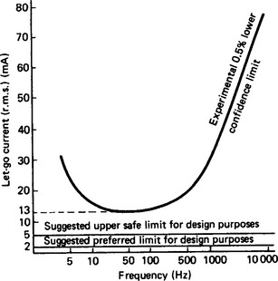
24.2.2.1 Hold-on current and permissible leakage
A typical characteristic showing the relationship of ‘hold on current’ to the frequency of the a.c. supply (Figure 24.1) indicates that the lowest values of current occur in the band of between 10 to 200 Hz which includes normal mains operating frequency.
24.2.2.2 Ventricular fibrillation
It is generally believed that the great majority of fatal electrical accidents are caused by ventricular fibrillation, the muscles of the heart going into spasms which prevents the heart acting as an effective pump. Death follows quickly in these circumstances due to lack of oxygen supply to the brain.
A great deal of experimental work to investigate such effects has been undertaken on animals and this has been central to the production of international Standards documents on the subject of electric shock and its effects on humans and animals.6
24.2.2.3 Limitations of experimental results
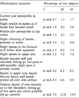
Because of the practical and ethical difficulties in experimenting on humans and because there are substantial variations between humans in their susceptibility to electric shock, the results from such research must be interpreted carefully so that adequate margins of safety are built into equipment and work practices which depend on this knowledge. A 0.5% risk of death is too high to be acceptable (Table 24.1). There is an essential difficulty in extrapolating from animal to human subjects and it is also the view that the susceptibility of human subjects can be considerably affected by subjective considerations, there is evidence that the effect of an electric shock is greater when either the shock is unexpected or the person is abnormally afraid of electricity.
24.2.2.4 Body resistance
The impedance of the human body from hand to hand or hand to foot is variable. It depends on the area of contact and is affected by whether the hands (or feet) are dry, moist or wet, the condition of the skin and on the frequency and voltage of the current. Values are thought to range from 1–10 kΩ. These variations are discussed at some length in the international Standards on electric shock.
24.2.2.5 The limits of safety
Recommendations about the safe operating limits are more useful for practical situations if stated in terms of supply voltages rather than ‘hold on’ or fatal currents, which are difficult to determine for real situations. Table 24.2 gives information which is in accordance with experience and practice. There can be no exact determination of these limits, but they are given as a guide.
Table 24.2
Approximate threshold shock voltages at 50 Hz a.c.
| Minimum threshold of feeling | 10–12 r.m.s. |
| Minimum threshold of pain | 15 r.m.s. |
| Minimum threshold of severe pain | 20 r.m.s. |
| Minimum threshold hold-on volts | 20–25 r.m.s. |
| Minimum threshold of death | 40–50 r.m.s. |
| Range for fibrillation | 50 or 60–2000 r.m.s. |
24.2.2.6 Effect of frequency
The results shown in Figure 24.1 indicate that 50 or 60 Hz is almost exactly right to produce the maximum excitation of a nerve ending, but that the nerves could not respond to substantially higher frequencies. Radio frequency burns may be serious however and there are possible situations where such oversimplified rules might not apply.
24.2.2.7 Respiratory arrest
Experience of electro convulsive therapy indicates that, in the absence of severe damage to the nervous system (which is rare), respiratory arrest from a shock involving only the head is unlikely to persist, unless presumably the shock has lasted long enough to cause a dangerous reduction of oxygen in the blood (anoxaemia). Since head shocks are very infrequent this is not of great importance. Even the possibility of asphyxia in persons unconscious from electric shock appears to be uncommon. However, there is experience that artificial resuscitation does aid recovery, although the reasons for this are obscure. It may simply be that some external massaging of the heart is sufficient to transfer enough blood around the brain to sustain life even if the blood is depleted in oxygen. The recommendation has traditionally been that when a person is unconscious and not breathing artificial resuscitation should be immediately commenced. Both works ‘first-aiders’ and electricians should normally be instructed how to do this since a medical diagnosis is rarely quickly available and prompt action is essential. Artificial resuscitation should be continued until breathing is resumed or for a minimum of 1 hour. (The operator should then stand by to give further help if breathing falters). Knowledge of the effectiveness of artificial resuscitation in practice is necessarily based largely on records of such action. There is an 85% chance of recovery provided that resuscitation has not been abandoned after a period of less than 1 hour. The patient should be under close observation for some time after recovery, as there is some danger of relapse.
24.2.3 Other injuries
Accounts of the after-effects of lightning strikes frequently refer to temporary or permanent impairment of hearing and sometimes ruptured eardrums. This is in most cases almost certainly caused by the intense acoustic shock wave sent out when a column of air (the lightning channel) rapidly expands on being suddenly heated to about 15000°C by the passage of the enormous current in a lightning discharge. The range of danger is probably limited to a few feet.
24.2.3.2 Arc eye
This is a painful condition resembling pepper in the eyes and develops some hours after exposure (even momentary) to an intense source of ultraviolet light. It occurs mainly when a person works near arc welding and looks directly into the brilliant light given out by the electric arc.
Fortunately ‘arc eye’ lasts only a short time, no more than a day or two, and although painful leaves no permanent injury. Treatment is by the application of a soothing lotion.
This complaint is easily prevented by the use of protective goggles with side protection, as worn by welders. The usual victims are assistants and bystanders without goggles, although ordinary glass cuts out much of the ultraviolet light.
Theoretically there is a risk of a form of cataract caused by prolonged exposure to infrared light which affects persons who work for long periods on glass furnaces, etc.
24.2.3.3 Fractures and torn muscles
Strains and fractures may arise from falls following an electric shock. e.g. from a crane or ladder. It may not be apparent at the time that the victim has suffered an electric shock and that the heart may be in fibrillation. If they are unconscious artificial resuscitation would be the advised first aid treatment.
24.2.3.4 Burns and side effects
Burns are probably the most serious after-effect of electrical accidents. They are the principal danger with direct currents or at very low voltages (below about 80 V). With low alternating voltages shock is the typical injury although there may also be severe burning. At extra-high voltages shock may not be as important it being the actual current and flash burns which tend to be severe with large areas of the body affected. Severe electrical burns have led to many deaths, usually after several days or even weeks of painful suffering. Burns may be of several types:
Contact burns: These occur when the person has touched a live conductor. They may be local and very deep reaching to the bone, or very small, being just an area of ‘white’ skin which may be easily overlooked at a post-mortem examination. The position of such small burns may be important in reconstructing an accident and should be recorded.
Arc burns: These may be extensive, and of any degree, particularly when there has been a high-voltage flashover. Provided that the person survives the initial wound and surgical shock, and the surface area involved is not too large, they are likely to make a good recovery because the injury should be largely sterile. They may, however, be badly scarred or even lose a limb. The large fault current levels which now exist on many low voltage distribution circuits poses a serious risk of arc burns if a flashover is caused. There have been a considerable number of fatalities to electrical staff due to this cause, usually when they have attempted to work on live low voltage (230/400 volt) busbars and switchboards without adequate training and proper insulated tools.
Radiation burns: These burns arise from short-circuit arcing and are, in effect, a severe form of sunburn. Some radio frequency (RF) equipment can also impart burns which can be deep. RF burns usually occur due to contact with the charged conductor but this will depend on the power output of the equipment and the frequency.
Vaporised metal: When an open fuse or small conductor fuses some copper (silver or tin) is vaporised and at close quarters this may burn or impregnate the face or hands. This is usually harmless unless it enters the eyes in which case the result is potentially serious.
Deep burns and necrosis: There is the potential danger of deep burns destroying tissues below the skin even though superficially there is only a small injury. Thus electrical burns, and in particular high-voltage contact burns, must be taken seriously and the person kept under medical supervision. However, such burns are rare.
24.2.4 Protection against electrical injuries
The obvious remedies for protecting personnel from electric shock, burns or radiation effects are to make live metal inaccessible and to keep persons separated from the dangerous plant, machinery or process. Another approach is to use protective equipment and defined work practices.
The Health and Safety Executive recommends many preventive measures in its various guidance documents but in particular it recommends the following through its Memorandum on the Electricity at Work Regulations 1989:7
• Using low (and safe) voltage.
• Insulating and/or enclosing live parts.
• Preventing conducting parts not normally live from becoming live by one or more of the following:
• Selecting equipment suitable for the environment in which it is to be used.
• Using equipment as defined in the maker’s instructions.
• Ensuring that electrical equipment is adequately maintained.
• Avoiding the use of electricity altogether where its use would be dangerous.
The following aspects are also worthy of note:
• Metalwork in the vicinity of functional conductors may become live by electromagnetic or electrostatic induction. Serious or fatal shock is unlikely on most circuits although some serious accidents have occurred due to mutual induction on parallel running power lines.
• When work is to be carried out on (dead and isolated) high voltage power equipment conductors these conductors should be earthed. Potentially dangerous electric charges may otherwise accumulate on unearthed conductors either from the slow release of charge from the high voltage insulation (dielectric relaxation) or from induction from adjacent circuits.
• It is possible to receive severe shocks from leakage over the surface of insulation at quite low voltages, e.g. 230 volt. Contamination of the surface of insulation by moisture and conductive salts can give rise to dangerous levels of surface leakage currents.
24.2.5 Toxic hazards
Toxic hazards arise as indirect results of electrical accidents. In this category are the hazards associated with the use of polychlorinated biphenols, which have been used in place of mineral oil in transformers, and those associated with carbon monoxide poisoning from incomplete combustion of insulation or oil.
Care is also needed in the handling of sulphur hexafluoride (SF6) which has been degraded by arcing since toxic by-products may have been produced.
24.2.6 Conclusions
Electric shock is not a single simple phenomenon and is not perfectly understood. The majority of electrical accidents occur at the common domestic and commercial electricity supply voltages. i.e. 230 and 400 volts, and a high proportion of electrical accidents are serious or fatal. Artificial resuscitation for persons unconscious after a shock is effective and should be continued for at least one hour or until hospitalisation.
Electrical burns may cause death in extreme cases where they are extensive. In other cases however, although they may be deep they are largely sterile and therefore tend to heal quickly and well, although they may leave scars. Damage to muscles may be serious and amputation may be necessary in very bad cases. Attention should be paid to small burns caused by contact with high-voltage conductors because there may be serious deep-seated damage (necrosis) which is not visible.
24.3 Failure of electrical equipment
There are two fundamental causes of failure of electrical equipment, mechanical failure or electrical failure of insulation.
24.3.1.1 Mechanical causes
The safety of electrical equipment depends to a large extent on sound mechanical design. The majority of circuit-breaker failures are mechanical rather than electrical in nature. Typical faults are loose joints leading to overheating or arcing and the existence of voids and contamination in insulation causing arcing and breakdown products. Where the insulation is bulk oil the products of arcing are themselves highly flammable (acetylene for example) and have often led to explosions.
Fractures may be caused by resonant vibrations of current carrying conductors either from purely mechanical movement or from electromagnetic forces leading to fatigue hardening and subsequent breakage. Where metallic elements are stressed in a corrosive atmosphere (e.g. damp or polluted atmospheres) along with alternating forces, failure may occur at comparatively low stress. Some steels, which under normal conditions exhibit considerable ductility, will fail at low temperatures by brittle fractures with no ductile deformation.
Mechanical failure of insulators may displace conductors and cause short circuits. Ceramic insulators are brittle but have great strength in compression. However ceramic insulators are vulnerable where they are used in tension or shearing situations. They are now largely confined to outdoor overhead lines and switchgear where their robust construction makes them less susceptible to mechanical failures although they are then vulnerable to vandalism.
24.3.1.2 Breakdown of insulating materials
The electrical breakdown of insulating materials may also occur as follows:
• Mechanically, as by friction or tearing.
• As a result of excessive electrical stress.
• As a result of excessive temperature (and occasionally very low temperature) or temperature cycling. The latter may cause mechanical stresses as a result of differential expansion or contraction.
• Chemical and physical reaction with other materials, e.g. oxidation, contamination or the leaching out of important ingredients which may lead to de-plasticisation, i.e. they become brittle. The ingress of water is a very common contamination leading to ‘treeing’ and eventual electrical breakdown.
Failure is rarely the result of inadequate electrical breakdown strength where reasonably pure materials are used. In practice, insulation is rarely designed to be stressed to more than 10% of its strength as determined by laboratory tests. It fails because of impurities, lack of homogeneity, the unavoidable variations in commercially available materials as well as in those natural products such as paper, wood and petroleum products. The insulation performance of most commercially used materials is now well documented and standard testing procedures have been established.
24.3.2 Particular equipment
Hazards associated with switchgear failure include fire, explosion and electric shock. There is a particular risk to the technical staff who require to operate high voltage switchgear and to conduct testing and maintenance on this equipment. Unfortunately oil circuit breakers and fuse switches have been the cause of many serious accidents and fatalities have not been rare. Some of the most expensive fire losses have also been caused by switchgear.
An important proportion of these accidents and losses are caused by failure of circuit breakers to operate correctly but many accidents are caused by mechanical problems with auxiliary equipment such as isolators and from failure of routine and emergency operating procedures. The causes of high-voltage switchgear failures are typically as follows.
• Poor maintenance leading to contamination of insulation and loose connections etc.
• Incorrect or inappropriate use of test equipment on live equipment.
• Unrestricted repeated operations of oil circuit breakers (OCBs) leading to breakdown of the oil insulation and/or to contact collapses.
• Hesitant operation of manually closed switches onto faulted circuits leading to panic opening on fault and the consequent fault arc drawn at the contacts of a non-rated switch.
• Failures of PTs (potential transformers, often referred to as VTs or voltage transformers) and failures of CTs (current transformers).
24.3.2.2 Transformers
Fires and explosions in oil-immersed power transformers have been less common than in oil-immersed switchgear and the immediate results are, on the whole, less damaging. However, because of the large amount of oil which may be released and ignited, oil-immersed transformers are potentially at least as dangerous and the consequences in terms of loss of power availability and pollution can be considerable.
Most discussions of transformer failure relate to interturn faults and their causes, but these cause a comparatively small number of fires, etc. Many incidents are generally associated with automatic tap-changing gear, while bushing failures, flashover and arcing at the transformer top, etc. (including some lightning damage) cause about the same number of incidents. Major transformer failures are comparatively rare events.
The main dangers are the spread of fire by the release of a very large volume of burning oil and the emission of clouds of black smoke but there may be secondary hazards such as plant being stopped by damage to cables and protection, control and alarm equipment even when the fire itself was not initially very large.
Typical failures and their causes are described below.
Lightning and voltage transients: These may cause external flashover of bushing insulations which may shatter or split oil-filled insulators, causing fires. If the voltage surge reaches a transformer winding it may cause a flashover above the oil and damage the winding insulation.
Internal flashover above oil: This can be caused by voltage transients as described above but there are other causes which are more easily eliminated. These are arcing caused by fractured conductors, sparking at loose connections, and badly made joints which provide ionisation above the oil level. Hot joints and connections are also suspected causes.
Interturn faults: Whatever the cause such faults are likely to develop slowly. The volts per turn are normally quite low (say 5–20 V for transformers below 2MVA) and will not sustain continuous arcing until a number of turns become involved but this may not apply where, in modern transformers, coils and turns are interleaved without spacers to improve surge voltage distribution. Overheating can be caused by short-circuited turns. Failures may go undetected by conventional protective relays as there is likely to be no significant change in through current. However some interturn faults can be detected by certain forms of monitoring and testing.
Failure of the insulation of the magnetic circuit: Such failure, e.g. of core frame, or clamping bolts, or between laminations, can allow parasitic eddy currents and local heating. The former may cause sparking and the evolution of arc gases. Such faults do not lead to immediate danger but contribute to the deterioration of insulation and oil. Also an accumulation of arc gas (particularly H2 and C2H2) in the airspace above or dissolved in the oil is a concealed explosion risk. Other faults which occur from time to time are due to poor hygiene and untidiness during manufacture and maintenance. Nuts, bolts, cut-off ends of wire and even spanners have been found wedged between windings. These can cause local stress concentration and heating with possible mechanical damage to insulation.
Overloading and ‘through’ faults: These will overheat the windings and cause cumulative damage to the insulation. They may not cause immediate danger unless they persist but the life of the transformer will be shortened.
There are advantages in using sealed transformer tanks. Experience indicates that in the absence of air (oxygen) the oil deteriorates much more slowly and less maintenance is necessary. There are drawbacks however. Unless there is an adequate space above the oil, which can be filled with inert gas, e.g. nitrogen, special means must be provided to allow for the expansion of the oil with rise of temperature, otherwise the tank may fail under the hydrostatic pressure developed. For this purpose internal ‘bellows’ or flexible diaphragms are sometimes provided.
Also, a sealed tank, unless it has a separate expansion chamber or conservator at the top, cannot be fitted with a Buchholz relay and it may be impossible to give full protection against slowly developing faults. A sealed tank should therefore be provided with a bursting disc or similar device as a major fault between phases or to earth, caused by lightning, fractured conductors, loose connections, etc., may otherwise cause the tank to rupture or the lid to be sprung before differential or overcurrent relays have time to operate the circuit-breakers.
Such faults are rare, and it may be that there are situations where the risk can be accepted, but this would not be the case for very large transformers, transformers in occupied buildings, or high fire-risk situations.
24.3.2.3 Cables and installations
Traditionally, high voltage distribution cables, if they were buried in the ground, were impregnated paper (tape) insulated, lead covered, steel wire armoured and served (i.e. protected with a sheath of material resembling bitumen impregnated sacking) and frequently further protected by ceramic tiles a few inches above the cable. Modern cables comprise plastic materials with metal extruded or wire armouring. Cables often have a life measured in many decades and many cables of early style construction may be found in use, particularly on public electricity distribution systems.
Medium voltage (400/230 V) distribution cables were steel tape armoured but sometimes tough rubber or similar sheaths were used in ducts. Such cables pose a very low fire risk. Modern cables mainly use plastic insulation. The main hazards are:
• Burst cable boxes at transformers, switchgear and other joints. Link, or street mains disconnecting, boxes which use the traditional bitumen insulation have been the subject of many incidents of failure, mainly due to voids in the bitumen, water ingress and to loose connections.
• Puncture by pneumatic road drills which causes short circuits and a shower of sparks, but which is often more alarming than dangerous because the sheath and armouring provide an efficient earth-return path. There have been incidents of serious burn injuries too however, the severity of the arcing being dependent on the power fault level of the transformers feeding onto that particular circuit. In cities these fault levels are often very high.
The evolution of clouds of black smoke from cable oil is a serious hazard because it hampers effective fire extinguishing operations, contaminates buildings and may result in the need for extensive cleaning and renovation work.
Although plastic insulation and sheaths such as polyvinyl chloride (PVC) are now common, and difficult to ignite, they will nonetheless burn if in adequate bulk and sufficiently preheated locally. However, when ignited PVC produces clouds of dense black smoke, as do some ‘rubbers’. There is then a substantial liberation of hydrogen chloride, which may corrode sensitive electrical equipment, e.g. in telephone exchanges and computer departments, and steel reinforcement bars in concrete.
Important cable tunnels should be provided with fire detection and monitoring equipment and possibly fixed fire extinguishing installations.
The relative positions of power, telecommunication, control, and alarm and safety circuits must be considered, to ensure that power short circuits and fires do not damage safety circuits.
Cable tunnels are perhaps more vulnerable to fortuitous ‘external’ fires than to short circuits, etc. The experience of the London Underground system shows that cable fires along the tunnels are likely to result from accumulation of rubbish ignited probably by sparks from the collector shoes of passing trains.
Inside industrial buildings, cables are usually drawn into conduit or laid in ducts or on trays. The possible spread of fire must again be considered. Attention must also be paid to the possibility of damage by vehicles such as forklift trucks and cranes.
Supply to ‘island sites’ in a work area presents difficulties. Under-floor ducts are subject to flooding and the entry of rubbish, flammable liquids and vapours. Overhead distribution busbars along a line of machines are frequently used, particularly where the position of machines may be changed at short notice when there is a change of product or method. The conductors are usually, but not invariably, covered with insulation, except at fixed points where provision is made for tapping off, and the whole assembly of busbars is enclosed in suspended metal trunking with provision for ‘plug and socket’ attachments or spur switch and fuse combinations. The construction must be considered in relation to possible damage by cranes, forklift trucks, etc., and the entry of water from a leaking roof or sprinkler systems.
It is preferable to make the connections to individual machines by cables with a flexible outer metallic screen, pliable armoured cable or by flexible conduit.
24.3.3 Protection against failure
Earthing is a complex subject. Its complexity should be apparent from a cursory reference to the current British Standard on the Code of practice for earthing which runs to 84 pages.8 In the context of the safety of most electrical installations however there are three main points to be made.
• It prevents the outer conductive casing of apparatus and conductors from assuming a potential which is dangerously different from the surroundings for any appreciable length of time although if a fault does occur inside the equipment the outer casing may actually be raised to a dangerous potential momentarily.
• The earthing connections must be sufficiently robust and conductive to allow sufficient current to pass safely in order to operate overcurrent or other protective devices promptly, including those for earth-leakage protection. Protective devices must be suitably rated for the fault currents which might be expected.
• Care must be taken against the occurrence of dangerous earth-potential gradients due to fault currents flowing in the terminations made to the general mass of earth. The ‘resistance areas’ of the earth electrodes of different systems should not be permitted to overlap to any significant degree. The purpose of this is to prevent faults on one system imposing dangerous voltages onto the protective (earthing) conductors of other systems.
Earthing is also used for functional purposes, for signalling and draining leakage currents. The needs of these uses can sometimes conflict with the safety objectives of earthing.
24.3.3.2 Interlocks and guards
Different classes of guards are described below.
Automatic guards: These move in advance of each operation or stroke of a machine and sweep or push the operator’s arm or person out of the way before the stroke is made, or automatically take up a position similar to a fixed guard before the danger can arise. They are sometimes used where material or blanks are fed by hand into the machine. They are best combined with trip guards, but are largely being replaced by interlocked guards.
Interlocked guards: These guards are moveable and whose movement is interconnected with the power or control system of the machine. They must be correctly adjusted before any potentially dangerous operation can commence.
Trip guards: These stop the machine or automatically cause other appropriate action to be taken immediately danger arises. They can often be combined to advantage with automatic guards or with positional and distance guards.
Positional and distance guards: These are often a rather elementary form of fixed guard, so placed as to keep an operator or other person at a safe distance from a machine which cannot be enclosed because of the nature of the material being handled or the work being done.
Electrosensitive safety devices: ‘Curtains’ of interlaced light beams are used extensively on machines such as power presses, bending brakes and guillotines, where the size and shape of the workpieces prevent complete enclosure with fixed guards. The risk of failure with such machines can lead to serious injuries of amputation and crushing so this demands that the design of these guards be a specialised matter with check circuitry and timing requirements to prevent failures to danger. There are international Standards which specify the safety integrity for these devices.9
24.3.4 Fires and explosions
Electrical installations are often cited as the cause of fires but this is probably due in large part to the difficulty in determining the actual cause of many fires. In effect electricity is an easy candidate for blame in cases of doubt when the more likely causes probably lie with carelessly discarded smoking materials and other banal causes. However electricity can cause fire in a number of ways.
Serious overloading is necessarily a fire risk, since most insulating materials are in some degree flammable (ceramics, minerals such as asbestos or alumina, and mica being the chief exceptions). Overloading or resistive heating at poor electrical joints and connections may also ignite other flammable material in the immediate neighbourhood, for example wooden and similar panelling over cable runs has caused disastrous fires in shops, theatres and other entertainment centres. A common cause of fires however arises through the inappropriate use of electrical heating appliances which simply radiate heat into materials until they ignite. Radiant electric fires, convector heaters, electric irons, cookers and incandescent lamps are involved.
Fires are also caused through arcing or sparking release of electrical energy. The use of electrical equipment in areas where flammable or explosive atmospheres may exist is the subject of extensive expertise and availability of specialist apparatus. Coal mines (which have firedamp, i.e. methane), oil refineries and chemical plants, are examples where this specialised apparatus is required. In the EU it is also the subject of the ATEX directive 94/9/EC.
HSE and HSC publications on electrical safety
HSR 25 Memorandum of guidance on the Electricity at Work Regulations 1989. HMSO
GS 6 Avoidance of danger from overhead electric lines.
GS 38 Electrical test equipment for use by electricians.
HSG 47 Avoiding danger from underground services.
HSG 85 Electricity at work—safe working practices.
HSG 141 Electrical safety on construction sites.
HSG 180 The application of electrosensitive protective equipment using light curtains and light beam devices to machinery.
Health and Safety Executive. http://www.hse.gov.uk
Department of Trade and Industry. http://www.dti.gov.uk
British Standards Institution. http://www.bsi.org.uk
European Commission. http://www.europa.eu.int
European Agency for Safety and Health at Work.
HM Stationery Office. http://www.hmso.gov.uk
D A Dolbey Jones. http://www.ukelectricalsafety.com
1. , Electrical Safety Engineering. Dolbey Jones, D.A., eds., 3rd edition. Butterworth-Heinemann, 1993. Chapter 1 Revised by
2. Gowers E., ed. Fowler’s Modern English Usage. Oxford University Press, 1965.
3. Gowers, E., Plain Words, Penguin, Harmondsworth
4. British Standars Iinstitution BS IEC 61508 Functional safety of electrical/electronic/programmable electronic safety-related systems
5. , Requirements for Electncal Installations, (IEE Wiring Regulations Sixteenth Edition). Harmondsworth: the Institution of Electncal Engineers and the British Standards Institution, 2001:7671. published jointly by
6. , Guide to effects of current on human beings and livestock. (In three parts) Published by the. BSI, 1998:60479. as PD 6519
7. Health and Safety Executive, Memorandum of Guidance on the Electricity at Work Regulations 1989, Publication HS (R) 25, HMSO, London
8. British Standards Institution. Code of practice for earthing. 1998:7430.
9. (and 1998) British Standards Institution. Safety of machinery Electrical equip-ment of machines, 1993.