
Prime Movers
MA Laughton, M A BASC, PhD, DSc(Eng), FIEE, FEng, Formerly of Queen Mary and Westfield College, University of London
IG Crow, BEng, PhD, CEng, FIMechE, FIMarE, MemASME, Davy McKee (Stockton) Ltd (Section 26.1)
H Watson, BSc, CEng, FIMechE, FIMarE, MemASME, FFB, Formerly Engineering Consultant (Section 26.2)
W Rizk, CBE, MA, PhD, FEng, FIMechE, W.R. Associates (Section 26.3)
E Goldwag, BSc(Eng), CEng, FIMechE, Engineering Consultant (Section 26.4)
LLJ Mahon, CEng, FIEE, FIQA, FIBM, Consulting Engineer (Section 26.5)
26.1 Steam generating plant
The production of steam at conditions suitable for supplying an engine or a turbine, or of providing steam for heating or process plant, is achieved by the transfer of heat from a primary energy source to water contained in a boiler, or steam generator, which in its most rudimentary form may be little more than a vessel heated from below. Currently, there are two major energy sources capable of supplying heat at a sufficiently high temperature and in a controlled and economically acceptable fashion. These are nuclear fission and the combustion of fossil fuels, such as coal, oil, natural gas and their derivatives. It is the latter, or ‘conventional’ energy source and its associated plant which are considered here.
26.1.2 Combustion
The combustion process for a fossil fuel is a rapid exothermic chemical reaction between the oxygen in the air and the combustible elements in the fuel. There are two such principal elements, carbon and hydrogen, which react with oxygen, thus:
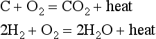
The heat release for carbon is approximately 7830 kcal/kg of carbon burned, and the equivalent figure for hydrogen is 33 940 kcal/kg. The requirements for the above reactions to proceed to completion are: first, a sufficiently high temperature to ignite the constituents; second, adequate mixing of the constituents; and third, sufficient time for the reaction to be completed. With regard to the ignition temperature, Table 26.1 gives an indication of these values for a number of fuels.
Table 26.1
Ignition temperatures for some common fuels in atmospheric air
| Fuel | Ignition temperature (°C) |
| Charcoal | 343 |
| Bituminous coal | 407 |
| Anthracite | 450–600 |
| Ethane (C2H6) | 470–630 |
| Ethylene (C2H4) | 480–550 |
| Hydrogen (H2) | 575–590 |
| Methane (CH4) | 630–750 |
| Carbon monoxide (CO) | 610–657 |
The mixing of the constituents and the reaction times are both major elements in the design of the furnace of a steam generator, which must be large enough and provide sufficient turbulence to ensure that these two requirements are met.
The absorption of heat in the boiler is achieved in two ways. In the furnace, where all the combustion takes place, heat is transferred to the water by conduction through the walls of its containing vessel or tubes, which receive heat by radiation from the burning fuel. At the outlet of the furnace the products of combustion are still very hot (probaby in excess of 1000°C), so that they remain capable of transferring heat; this time by convection. This heat can be used in non-superheating boilers to further heat the water, while in superheating boilers, as the gas passes through the convection zone, it may progressively be used to superheat the steam first produced in the furnace, and eventually the cold incoming feedwater. Finally, the gaseous products of combustion are ducted to a chimney (sometimes via flue gas clean-up devices) and so any residual heat left in these gases is lost. Nonetheless, the efficiency of steam generating plant, as defined by the ratio between the heat energy of the steam leaving the boiler and the chemical energy of the fuel entering the furnace, can be high, with typical figures in excess of 85% for coal fired plant, rising to as high as 98% for compact oil fired boilers.
With regard to efficiency definitions, care should always be taken to establish the basis of the efficiency calculation, as the heat content of the fuel is generally assessed differently in Europe and the USA. In the USA the higher heat of combustion (QH) is used which incorporates the heat of vaporisation of water (that is, it is assumed that all water vapour formed by combustion is condensed). The lower heat of combustion (or lower calorific value, QL) is derived by assuming that the products of combustion remain in the gaseous state. It may be shown that
where W is the weight of water formed per kilogram of fuel. European practice tends to favour the use of QL.
Calorific values are obtained experimentally by means of a bomb calorimeter in which combustion occurs at constant volume and the derived value QH. QL is obtained from the above relationship and, in fact, refers to combustion occurring at constant pressure.
The major heat loss from a boiler has already been identified as the heat loss up the stack, or chimney. Other losses may arise due to incomplete combustion of the fuel, leaving carbon in the ash or by producing CO rather than CO2. In practical installations it is always necessary to use more than the theoretical air requirements to be sure of complete combustion. However, in order to keep the stack loss to a minimum this excess must be carefully controlled. For fuel oil fired installations, excess air is typically in the range 5–10% by weight, referred to the theoretical air requirements. Corresponding figures for a pulverised coal fired unit would be 15–20%, while for a stoker fired boiler the figures would be in the range 30–60%. The remaining inherent loss for a boiler arises due to the moisture content of the fuel and the production of water vapour in the combustion process, while the remaining avoidable loss arises from radiation from the boiler setting. This latter loss can, of course, be controlled by providing the unit with good insulation.
26.1.3 Sources of chemical energy
The fossil fuels available as suitable heat sources occur naturally in the earth and are the remains of organic materials once found living on the Earth’s surface. It is not surprising, therefore, that the properties of individual fuels vary markedly from place to place and that the fuels contain many trace elements which can in some cases profoundly influence their combustion characteristics. It is necessary, therefore, that the boiler plant designer knows the type of fuel that will be burned and also fully understands the effects the properties of the fuel will have upon all his design parameters. In consequence, much effort has been directed towards understanding the combustion of conventional fuels which are commonly used, and considerable data are available on the fossil fuels (oils, natural gases and coals).
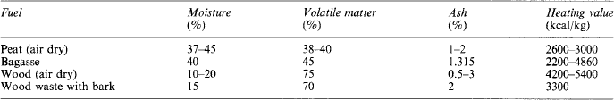
As well as fossil fuels, less important, but common, vegetable fuels such as peat, wood, wood bark, bagasse (sugar cane residue), grain hulls and residues from coffee grounds and tobacco stems are useful sources of heat. Sometimes gases, tars and chars produced as by-products in steel making or oil refining processes are used. In many instances when waste products are to be used they will be burned in conjunction with the major fuels (oil, coal and gas).
26.1.3.1 Liquid fossil fuels
Fuel oil, owing to its relative ease of handling and storage, the absence of large quantities of residual ash and its high calorific values, had by 1970 become a most attractive fossil fuel. Since then, however, its relative cost with regard to other fuels and the uncertainty of its long-term availability have both tended to reduce its competitiveness. Nonetheless, particularly in the case of smaller boiler installations, oil remains a viable fuel.
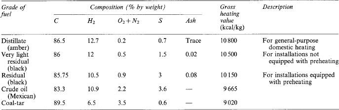
The type of oil burned for steam generation can vary from light distillates having low viscosity and low specific gravity to the heaviest residual black fuel oils with very high viscosities. Occasionally, crude (or unrefined) oil may be considered for use directly in the boiler furnace; however, the presence of highly volatile fractions (normally removed in a refining process) may prove troublesome. Typical characteristic of fuel oils are shown in Table 26.2. Despite the low percentages of ash indicated in Table 26.2, trace elements such as vanadium, sodium and sulphur can be responsible for a number of operating problems.
A further source of liquid fuel is oil derived from oil-shale, which is a fine-grained, compact, sedimentary rock containing an organic material known as kerogen. Shale oil is obtained by heating the rock to 470 °C. (The yield is normally about 115.1 per tonne of rock.) Substantial reserves are known to exist in North America, in some parts of the Middle East, in China and in Australia. The use of shale oil in steam generators may be restricted by cost, but consideration is currently being given to the direct combustion of oil-shale in boilers.
26.1.3.2 Gaseous fuels
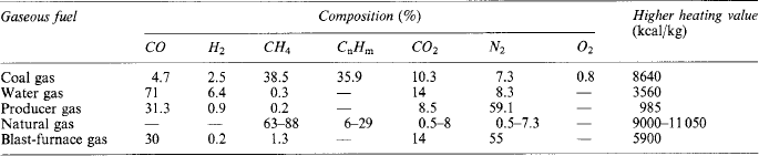
In many ways gas can be considered the most easily used of all the chemical fuels. It is capable of easy transportation from the producing or gathering plant to the consumer, and the use of pipelines can eliminate storage problems, particularly for very small installations. Care is required, however, in large boilers to avoid the occurrence of explosions during unit ignition or at other times when ignition may be lost. As may be expected, for clean gases complete combustion with a low excess air requirement is possible and the combustion does not produce smoke; additionally, it is substantially free of ash. Typical analyses of gases burned in steam generators are shown in Table 26.3. Blast-furnace gas is included in Table 26.3 for completeness, although it is usually available only as a by-product of a steelworks. It is normally heavily contaminated with dust, and great care must be taken to avoid plugging of fuel pipes or furnace fouling. Clean-up is usually achieved by a washing process.
26.1.3.3 Solid fossil fuels
Coal is a major fossil fuel throughout the world and has been in use for many decades by the industrialised nations. It is found in many forms, ranging from anthracitic through bituminous and sub-bituminous to lignitic. With so many sources and with such variations of type and quality, it has been found impossible to produce any generalised analysis for this fuel which will predict its behaviour in the boiler. As opposed to oil and gas, coal contains relatively high ash levels, which in turn will contain trace compounds (such as SiO2, AlO2, TiO2, Fe3O4, CaO, MgO, Na2O, K2O, Mn3O4 and P2O5) whose presence and effects need to be recognised if efficient and reliable coal combustion is to be achieved.
With these reservations in mind, however, it is possible to divide coals into certain classifications. In Europe the International System of Classification is generally used, while in the USA the ASTM System is used. Both systems have attempted to group coal together by their heating values, moisture contents and volatile matter contents.
Anthracitic coals have a high heating value, are non-agglomerating, have low volatility and very high fixed carbon content (in excess of 85%). Bituminous coals have a heating value not less than 5700 kcal/kg, and are agglomerating, while sub-bituminous coals can have heating values as low as 4600 kcal/kg. Lignitic coals are characterised by high moisture contents (up to 60%) and heating values lower than 4600 kcal/kg.
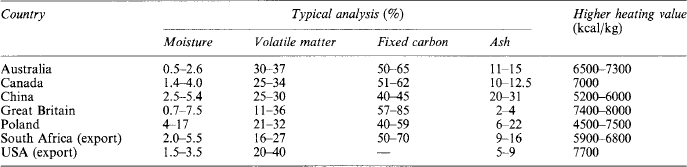
To provide an indication of the variations of coals worldwide, some of the more significant producers are listed in Table 26.4, together with corresponding typical hard coal properties.
26.1.3.4 Other solid fuels
Other fuels, mainly vegetable or vegetable waste, have been found to be useful. Peat is, in fact, burned by certain public utilities. Wood and wood wastes as well as bagasse waste are also well-known fuels, while, more recently, trials have been conducted into the use of industrial and domestic refuse as a boiler fuel. Some indication of the properties of these fuels is given in Table 26.5.
26.1.4 Thermodynamics and hydrodynamics of steam generating plant
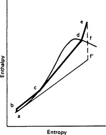
In a conventional steam generator the working fluid (water) receives heat from the chemical reactions occurring between its fuel and the air, and in an ideal situation the working fluid is at constant pressure. In a real boiler there is a pressure drop between inlet and outlet due to the effects of friction; however, the process can reasonably be represented by the line bcde in Figures 26.1 and 26.2. Initially, the incoming water or feedwater to the boiler has to be pumped into the boiler and this is represented by the line ab. At inlet to the boiler (b) the water enthalpy will be subcooled and will first need to be heated to saturation at c. At c its mass quality (x) is zero. Mass quality may be defined as,
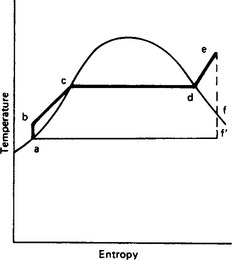
where Wg and Wf are the flow rates of steam and water, respectively. A mass quality definition can also be stated as
where h is the enthalpy of the working fluid, hf the enthalpy of saturated water at the same pressure and temperature, and hfg the latent heat at the same conditions.
In equation (26.1) x can vary between zero and unity, while in equation (26.2) x can assume negative values if the fluid is subcooled and values greater than unity when the fluid is superheated. In the range 0 ≤ x ≤ 1, the values of x derived from equations (26.1) and (26.2) are identical if thermodynamic equilibrium exists.
Between c and d the mass quality increases from zero to unity as steam is produced, until at d the working fluid is completely transformed into dry-saturated steam. If the boiler is equipped with superheaters, further heat can be added, to achieve a final condition at e. The processes between c and d occur at an essentially constant temperature (the saturation temperature equivalent to the pressure in the boiler), while in the superheat region the added heat causes the steam temperature to rise.
At point d or e the steam can be used to provide heat for process plant or be used to drive a work producing engine or turbine. If steam leaves the boiler at d, which is a dry-saturated condition, it is evident that the removal of energy from it by heat transfer or by work in an engine will cause it to start to condense, and x will fall. However, if the steam is initially superheated to e, it can provide an amount of work approximately equivalent to the drop in enthalpy (he − hf) before any moisture is formed: this is the great advantage of superheat. Nonetheless, many applications, particularly in the process industries, require only heat and the added complications of providing large amounts of superheat are avoided, providing that process temperature demands are compatible with available boiler pressures.
By contrast, in cases of power generation, high pressure and temperatures are thermodynamically attractive, as in the expansion of the steam to vacuum in a condenser (point f′ in Figures 26.1 and 26.2), so making the term (he − hf) as large as possible. The boiler may then be said to be working as part of a regenerative cycle with steam under vacuum at f′ being condensed along f′ a to a pump at a, where it is pressurised and returned to the boiler at b.
Mixtures of these two systems are common, particularly in industry, where some electrical power as well as process steam is required. However, in all cases the steam generator must provide the steam at the desired conditions, and to achieve this the boiler designer must be fully aware of the processes involved within the working fluid as it moves from b to e.
For the simplest type of industrial boiler, the shell or fire tube boiler, where only modest steam pressures are available and little or no superheat is produced, the combustion occurs in furnace and fire tubes and the products of combustion pass down further tubes (called smoke tubes). The tubes are contained within a vessel (or shell) which contains essentially non-flowing water, heated by the tubes passing through it. The rate at which heat can be transferred to the water is controlled essentially by the properties of the water. If the rate of heat transfer is poor or a very high flux is provided by the furnace, overheating of the tubes may occur and the material may fail. Information on these heat transfer rates, either by experience or by experiment, are therefore required by the designer.
For higher pressures and capacities and for applications calling for appreciable amounts of superheat, the roles are reversed, in that water occupies the tubes, which now form the enclosure of the furnace. Such a boiler is known as a water tube boiler. In such designs, water flows in the tubes and it is induced to do so either by means of a pump or by the ‘natural’ effects induced by heating water in inclined or vertical tubes so that the steam so formed is free to rise.
26.2 Steam turbine plant
The steam turbine is a prime-mover well suited to the direct drive of two- or four-pole high-speed a.c. generators for power-supply networks. The associated steam-raising plant can be fired by a wide variety of fuels—fossil, nuclear and such unusual fuels as city refuse, sawdust and sugar waste. The turbine can accept a low exhaust temperature (making possible a reasonable thermal efficiency) and a moderate inlet temperature (permitting a long life, e.g. 200 000 h). The turbine is best suited to high power ratings, as parasitic losses tend to be independent of size; further, output ratings can be raised without a pro-rata increase in materials, so giving a higher power cost ratio.
Steam turbines are constructed in the range 5—1300 MW. At the highest ratings the only comparable prime-mover is the hydraulic turbine, while at the lower end of the range the steam turbine competes with the diesel engine and the gas turbine.
Besides generator drive, the steam turbine is applied to ship propulsion and to rotary compressors. This section deals exclusively with electric power generator drive applications.
26.2.1 Cycles and types
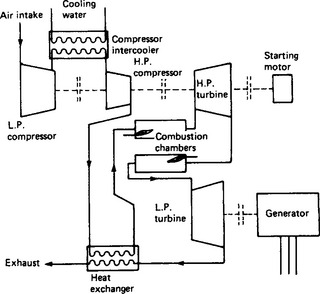
Most fossil-fuel-fired generating stations use the reheat cycle. Currently, outputs span the range 200–1300 MW. Common steam conditions are 16 MPa, 540°C (2350 lbf/in.2, 1000 °F). Occasionally supercritical conditions, e.g. 22MPa and above, are met, and sometimes there are two stages of reheat; but the one-stage reheat subcritical cycle here described is more common. The British advanced gas-cooled nuclear-reactor plant also uses this cycle, with outputs currently of 660 MW.
In Figure 26.3, ABCD shows the conditions of steam throughout the cycle, and Figure 26.4(a) gives the plant arrangement. Steam is expanded in the high-pressure (h.p.) stage down to near-saturation and is then returned to the boiler for reheat to the original temperature but at lower pressure. It then expands in the low-pressure (l.p.) stage until it becomes as wet (usually not more than 13% wet) as the final blades can tolerate.
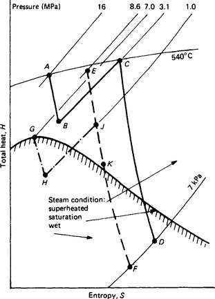

Figure 26.4 Various turbine cycles. (a) Reheat cycle, commonly used in fossil fuel and AGR power stations; (b) Non-reheat cycle, used for lower power; (c) Cycle for pressurised-water and boiling-water nuclear reactors; (d) Extraction cycle; (e) Back-pressure or ‘total energy’ cycle; (f) Combined cycle, one of various steam and gas turbine arrangements
The cycle is efficient and eases the design of last blading, which is usually the critical problem in turbine development. By using reheat, less steam per megawatt-hour is needed and this means shorter blades at exhaust. The cycle usually gives an exhaust somewhat drier than others, reducing the blade erosion hazard. However, all this is at the expense of some complication and extra boiler size and the smaller units—say under 100 or 200 MW—use the simpler non-reheat cycle.
26.2.1.2 Non-reheat cycle
This is shown by the line EF, in Figure 26.3, and the plant layout in Figure 26.4(b). Steam usually at 5–8.5 MPa (900–1250 lbf/in2) is expanded through the turbine to exhaust from the condenser without return to the boiler. This simple and compact machine is usually constructed in a single cylinder. The plant has a lower first cost than that for reheat, but is 8% or more higher in fuel consumption.
26.2.1.3 Pressurised-water and boiling water reactor cycle
The steam conditions are given by line GHJF and the layout in Figure 26.4(c). Water-cooled reactors require a special cycle because steam is supplied at an unusually low temperature, about 280°C (540°F). The steam is saturated and when expanded, quickly becomes wet. Water in the h.p. stages can cause damage, so the steam is taken out of the turbine after the h.p. stage and put through a drier—usually a device that uses the motion of the steam to separate water from it. It is then reheated by steam bled from the main supply to a surface heat exchanger alongside the turbine.
The cycle is not efficient and turbine design must take care of the potentially damaging effects of water in the steam. However, it suits the pressurised-water boiling-water reactors and their economics. Machines of up to 1300 MW are in service using such cycles.
26.2.1.4 Extraction cycle
This cycle, line EKF in Figure 26.3 with layout in Figure 26.4(d), is particularly economical where steam is used to supply a process as well as to generate: a typical example is the desalination plant fed with steam from a turbogenerator, an arrangement in demand in countries where industry and population develop in desert areas. Here, power units of 20–120 MW are in operation, and pass-out steam feeds multi-flash sea-water desalination plants.
Steam is expanded in the h.p. stage of a turbine and is then withdrawn. A control system acts to take off as much steam as the process requires. The steam that the process does not need is then returned to the turbine to expand and do work in the l.p. stages and ultimately to exhaust to the condenser under vacuum.
26.2.1.5 Back-pressure (‘total energy’) cycle
Figure 26.3 shows the cycle by line EK, and Figure 26.4(e) shows the plant diagram. While the turbine is efficient in itself, with stage efficiencies of around 80%, the basic cycle has a much lower efficiency (usually 30–38% overall for power stations), mainly because over half the energy in the steam is lost in the exhaust. With the exhaust pressure usually as low as 5 kPa (0.75 lbf/in2) the steam is at only 33°C (92°F). It is difficult to find ways to use energy at such a relatively low temperature and so the very considerable heat in the exhaust is discarded to a condenser.
Some factories need steam for process work, e.g. at upwards of 150°C and at a pressure useful enough to drive the steam to and through the process plant—say 350–1000 kPa. District heating schemes usually require water at 65°C and obtain it from steam at around these conditions.
The turbine can be arranged to exhaust at these higher pressures and to pass all its exhaust steam to the process or to the district-heating scheme. Although the higher back pressure of, say, 700 kPa makes the machine much less efficient than with a more normal condensing turbine, the cycle as a whole is efficient because the turbine exhaust heat is not lost. Thus, a back-pressure plant generating electricity and exhausting to a factory process can have a thermal efficiency of 70% compared with 35% for a normal power station.
The basic problem with back-pressure units is that the heat required near to the turbine-generator rarely keeps pace with the electrical power required locally. Basically, it is easier to distribute electricity to more distant parts than to send heat: back-pressure units are therefore usually small. Confining their power and heat output to nearby use, they are rarely of more than 20 MW rating and often much less. There may well be a future for such cycles in the conservation of increasingly costly fuel, and the potential of such ‘total energy’ schemes must inevitably attract more attention.
26.2.1.6 Combined cycle
The ideal engine has a high inlet thermodynamic (absolute) temperature T1 and a low exhaust temperature T2. The highest attainable Carnot efficiency is (T1 − T2)/T1. The steam turbine has only a moderate T1 but a very low T2, so that its efficiency is normally higher than that of the gas turbine, for which T1 is high but so is T2.
The combined cycle aims to optimise conditions with a cycle that uses the high T1 of the gas turbine and the cool exhaust of the steam turbine, Figure 26.4(f). The cycle works as follows.
Fuel is burnt in the combustion chamber of a gas turbine, which generates electricity and exhausts to a heat exchanger. Here the hot gases boil water to raise steam which then drives a steam turbine which also generates electricity. The steam turbine exhaust is changed to boiler feed water in a condenser.
A number of such plants are in service and more are being built because of their high efficiency. They also have the quick-starting ability that the straight steam turbine lacks. Also they can offer power early in the building programme by installing the gas turbine first and the steam turbine later.
They have as yet a reliability somewhat lower than that of simple steam plant, and the gas turbine has a shorter life. The availability is more acceptable if natural gas is used rather than oil. A common arrangement is to take about two-thirds of the power output from the gas turbines and one-third from the steam turbine; say, two gas turbines and one steam turbine per unit.
While this cycle is as yet limited to gas and carefully prepared oil, there are prospects of its use with coal. The pollution problem is creating so strong an emphasis on clean burning that new combustion methods are being developed for coal. Pressurised, fluidised bed combustion is one; gasification is another. Such arrangements promise to produce a gas clean enough for gas turbines to use. So there is a prospect of using the combined cycle to give thermal efficiencies of around 45% using coal, which is the most profuse fossil fuel.
Combined cycles are not necessarily arranged as in Figure 26.4(f). For instance, fuel can also be burnt in the gas-turbine exhaust to raise more steam (see also Section 26.3.3).
26.2.2 Turbine technology
There are two basic types of blade—impulse and reaction. In the impulse type (Figure 26.5(a)) all the expansion of steam is done in fixed nozzles and the high-velocity jets so created drive the rotor blade. In most machines the expansion is in successive stages, of which there are usually as many as 20 from inlet to exhaust, each comprising a row of nozzles and a row of moving blades.
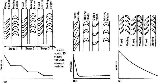
Some turbines use a ‘Curtiss’ stage (Figure 26.5(b)) to drop the temperature quickly at inlet or to shorten the machine. This stage takes a more than usual pressure drop. An exceptionally high jet velocity results and this is converted to work by driving two or more rows of blades from the one jet. The sketch shows how this is done using guide blades to re-direct the steam leaving the first row.
In reaction blading (Figure 26.5(c)) the moving blades are driven not only by the steam jets from preceding nozzles: they act as nozzles themselves and the jet they create helps to propel them. Therefore, pressure is lost both in the fixed and moving blades and power is produced both by impulse and jet reaction.
In practice, few machines are purely impulse and none are purely reaction. In the modern so-called impulse machine all blades have a degree of reaction and generally this increases towards the exhaust. In some designs the amount of reaction is more marked, depending on the background experience of the manufacturer. Properly designed, there is little difference in efficiency between the impulse and reaction types.
In all but a few small machines, the steam flows along the shaft, parallel to the axis. There are two unusual designs in which this is not so. One is the Ljungström turbine, in which steam flows radially outwards through concentric rings of counter-rotating blades. The other is the Terry turbine where the steam jets travel at an angle inwards to drive against hollows in a rotating disc. The Ljungström turbine is confined to medium outputs, while the Terry turbine is used only for very low powers, e.g. for driving small auxiliaries.
Both these types are now rare. Most modern machines have axial flow with either reaction blading or a combination using h.p. stages of mainly impulse and l.p. stages of mainly reaction design.
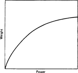
26.2.2.2 Size effects
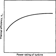
The steam turbine is notable in that higher outputs can be achieved without a pro-rata increase in mass and cost. A power increase of 20% is achieved by using blades 20% longer and this increases the mass of the machine by much less than 20%. So the mass/output ratio is a curve such as that shown in Figure 26.6. Also, parasitic losses such as gland loss, etc., do not increase at the same rate as power does when greater outputs are used. Thus, increased size produces some gain in efficiency (Figure 26.7).
Taking these two factors together there is a financial gain to be got from increased size (Figure 26.8). Two important points to be noted, however, are:
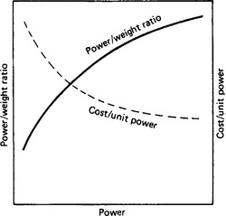
(1) If size is achieved at the expense of reliability, the financial gain may well become a loss; and
(2) The gain due to higher outputs is best achieved if blades are lengthened and the change confined to this and to directly related issues. It will be only partially realised if, say, increased exhaust area is achieved by using more exhausts and hence more cylinders, rather than if the change is confined to longer blades.
26.2.2.3 Part load
The steam turbine performs best at full load, where the whole system of nozzles and blades operates with proper steam velocities, with minimal throttle losses in valves. It will be less efficient on part load: energy is wasted by throttling down the pressure in valves. The steam jets are slow and do not strike the blades at the right angle, and the exhaust is too hot. If a turbine has to be used frequently at part load, it can pay to adopt nozzle rather than throttle control. The arrangement shown in Figure 26.9 could show advantage over that shown in Figure 26.10.
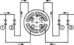
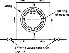
In nozzle control, part load is achieved by using fewer nozzles and unthrottled steam. The technique is more common overseas than in the UK, though mechanical difficulty tends to make it less suitable for large machines.
26.2.3 Turbine construction
It would be ideal to have all turbines as simple as the single-cylinder machine, this is shown diagrammatically in Figure 26.11(a). In fact, these are built for outputs up to 80 or 90 MW. Above these, the longer blades make two or more exhausts necessary and these need a separate shaft. The next step is to Figure 26.11(b), which in the non-reheat form provides outputs of 250 MW or more.
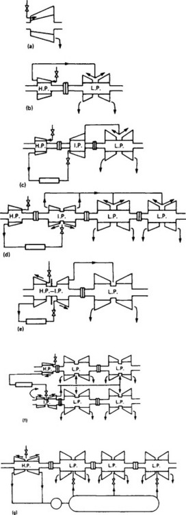
Figure 26.11 Forms of turbine: (a) simple cylinder, non-reheat; (b) two cylinder, non-reheat; (c) three cylinder, reheat; (d) four cylinder, reheat; (e) reheat with combined high power and interim power; (g) nuclear tandem for pressurised-water reactor
When reheat is adopted there are two hot inlet flows, one at high pressure and a second at an intermediate pressure. Some makers mount each on a separate shaft, giving the h.p., intermediate-pressure (i.p.) and l.p. arrangement of Figure 26.11(c). Others take both inlets to a common h.p.-i.p. rotor, Figure 26.11(e). The latter is common American practice.
The arrangements so far described are for rated speeds of 3000 or 3600 rev/min. An important design factor concerns the last blade size: increase in blade height permits the number of exhausts to be reduced. Current UK designs for 3000 rev/min turbines include blading heights up to 0.95 m on a mean diameter of 2.65 m. For 300 MW these use two exhausts as in Figure 26.11(c) and four for 600 MW, as in (d), or alternatively six where the higher efficiency obtained is economically justified.
Developments may lead to even longer blades, capable of 600 MW with two exhausts as in Figure 26.11(c) provided that low coolant temperatures are feasible. In some areas of the world these cannot be obtained, and only low area exhausts are justified.
Where the power rating is such that the exhaust area is beyond the capacity of the largest blades, the necessary area can be provided by a two-shaft or cross-compound arrangement, e.g. Figure 26.11(f), or by halving the speed as in the 1800 rev/min 1300 MW machines such as that in Figure 26.11(g). These arrangements accept, as most do, that eight exhausts on a single high-speed shaft line would not be a preferred solution.
There is a compromise between the two methods shown by using a cross-compound with a high-speed, h.p.-i.p., line and a low-speed, low-pressure line, either 3000/1500 or 3600/1800 rev/min depending on grid frequency. Inherent in these schemes is the fact that the lower speeds make it possible to use much longer blades and so enlarge the exhaust area and machine output. However, they do so at the expense of more metal for the low-speed rotors and casings, which are massive in comparison with those for a high-speed set.
Engineering solutions to the problem of increased output are always evolving and much larger turbine sizes than the current 1300 MW units could, no doubt, be devised. The limit tends to be imposed not by technical aspects of turbines, but by economics and by factors other than the turbine itself. An influence that the turbine contributes to this limiting of growth, however, is that the return tends to level off as size increases and can easily be nullified or even reversed if availabilities of the large machines fall even slightly beneath those of the smaller ones.
26.2.3.2 Foundations
The large turbine generator is supported some 10–12 m above the basement, a space that accommodates pipes, condensers and drainage. Supports were formerly mostly of reinforced concrete, but steel supports are increasingly preferred. They can be accommodated more readily into a building programme and are more predictable in their dynamic characteristics.
The block usually takes the form of an entablature supported on columns. It must be designed so that the shaft runs smoothly even though it may be slightly out of balance. The foundations must sometimes accommodate earth tremors. Both these requirements are better served if the structure is in steel than in concrete, because with steel the stresses, loadings and masses commercially used give a lower and more predictable and natural frequency. Vertical frequencies of about 10 Hz and sway frequencies somewhat lower are typical of such designs. These frequencies are substantially less than the shaft frequency of 50 Hz or half-shaft frequency of 25 Hz, both of which must be avoided if resonance is not to occur.
Concrete foundations tend to give calculated frequencies nearer 50 Hz, either above or below it. If the softness of the earth beneath the foundations is allowed for, these fundamental frequencies fall usually to well below 50 Hz, but not so low as with steel. While concrete foundations have given good service, their response is more difficult to predict and they are less likely to accommodate shaft and earth dynamics so acceptably as do steel foundations. Also, steel is usually more amenable to a quick station-building programme. However, in many countries concrete may be more economic and the choice has to be made on the circumstances.
26.2.3.3 Lubrication
The security of the turbine depends on a continuity of oil supply to its bearings and on the safe functioning of its hydraulic control gear. Further, the fire record in power stations shows that the oil system may play a part in starting or aggravating a fire. It pays to invest thought and money to make the oil system completely reliable and safe. Oil systems involve quite large flows with large turbines, partly because the bearings (especially the thrust block) have turbulent conditions in them unlike the less power-absorbent laminar conditions in former 30 MW sets. Special measures aim to reduce these power losses but they can still reach 3.5 MW for a 660 MW set.
Most machines have shaft-driven main oil pumps, usually centrifugal, primed by jet pumps or pumps driven by a hydraulic motor. The main pumps are backed by a.c. full-duty pumps and by a battery-operated d.c. emergency pump to provide oil until the shaft stops should there be an a.c. failure. Sometimes a small a.c. pump is fitted for use on barring. Shafts are generally jacked by h.p. oil to help starting.
In many arrangements the main oil pump also supplies the control gear with fluid; in others, separate pumps are used and feed control gear at much higher pressures than are used in the lubrication system. A fire-resistant fluid is sometimes used for control but is rarely considered for lubrication. The lubricant fluid is still oil, which can burn: it is therefore essential to design the oil system and fire-fighting plant to reduce fire risk. Attention is needed especially to pipe flange and coupling design. Any item that may fracture or leak oil should be eliminated or designed to reduce risk.
26.2.3.4 Governing
The governing and protection system operates control valves both to keep the speed steady within narrow limits and to prevent overspeed on sudden loss. The large turbine has stop and throttle valves at its inlet, and stop and interceptor valves at the i.p. inlet from the reheater. Usually, speed control is by adjusting the h.p. throttles. Overspeed on sudden load loss is prevented, first by closing the throttle valves and interceptors and then, should speed still rise, closing the h.p. and i.p. stop valves. Overspeed prevention requires fast valve action, usually well under 0.5 s closure and in some cases down to 0.15 s. The modern large machine has a high power/mass ratio and a sudden loss of full load can cause accelerations of 10–15% of full speed per second. This allows only a short time to cut off the steam supply, a situation aggravated by the stored energy of steam already in the pipes and spaces downstream of the valves. It is an important aspect of machine arrangement to minimise such spaces, e.g. using short steam loop pipes.
Other protective circuits besides overspeed operate the valves. The list usually includes low bearing-oil pressure, high vibration and poor vacuum.
Mechanical governors of large machines operate the steam control valves via hydraulic relays and power amplifiers and, eventually, by a servo-motor whose position is determined by speed level and held by a pilot valve and feedback. There are variations on this theme, some having an acceleration element.
Electric governing is becoming more general. Speed accelerations are sensed electrically and translated to an error signal in some adjustable way within the electric governor. The final movement and positioning of the steam valve is still hydraulic.
Some small machines use mechanical relays between speed sensor and valve, but most use hydraulics or electrical signalling and hydraulic power for valve movement. Lubricating oil is normally used, with pressures taken from the main oil pump at 0.35–2 MPa (59–300 lbf/in2) but occasionally separate pumps are used for control and with pressures as high as 17 MPa. Fire-resistant fluids are used in the control systems of some large machines. In US practice, double piping is often called for if lubricating oil is used. The reason is that oil leaks are retained within the pipes rather than spill to atmosphere and cause a fire hazard.
26.2.4 Turbine support plant
The condenser itself is large and costly consisting essentially of tubes through which cooling water is pumped and about which steam and air move. The steam is condensed and the air extracted. The condensate is drawn out by extraction pumps and in an efficient condenser it is nearly at the same temperature as the steam. It is returned to the boiler to use again. For every 1 °C by which the exhaust temperature is lowered in a typical 100 MW set, up to 0.5% extra fuel is burnt. Thus, a larger surface area of tubing allows the exhaust to be brought down more nearly to the coolant temperature; but, of course, this means a higher plant cost.
Having decided the surface area, however, it is important to use it properly. A particular offender is air, which can increase the exhaust temperature if it enters the condenser in large quantities, blanketing the tubes from steam. Excluding air is important: the condenser must extract such air as does enter without its forming pockets and blankets.
In the past, tubes have usually been made of brass. Where there is a severe corrosion risk, cupro–nickel is sometimes used. Dosing is usually employed, e.g. by ferrous sulphate injections, especially where there is a risk of corrosion or of erosion. Sometimes a cleaning gear is used in which shoals of floating balls pass through the tubes, are recollected and put back into the tubes.
Thin tubes of titanium are now becoming more usual. The evidence so far is that they offer much greater resistance to corrosion and erosion and often promise economic advantage.
With the high-steam conditions now used, it is vital to keep salts from the boiler and tube fixtures usually involve expansion or welding. Packings are rare. Sometimes anti-leak measures extend to the use of double tubeplates, with pressurised distilled water filling the space between the two plates. This ensures that, if there is a leak into the steam space, it will be of clean water and can be monitored. Large condensers usually have arrangements for on-load cleaning.
Ejectors are used to remove air from the condenser. Currently, steam-jet ejectors appear to be in favour but there are various alternative electrically driven ejectors.
The cooling water system can be quite elaborate and usually involves a considerable amount of both mechanical and civil engineering. In a typical British coastal 660 MW unit, for every 1 kg of steam that enters the condenser, about 30 kg of cooling water must be pumped through it. This means a flow of some 1000 m3/min. A 1300 MW nuclear unit on the Californian coast uses as much as 3000 m3/min of cooling water.
There is no standard cooling system using sea-water: the arrangement and equipment are made to suit the circumstances. Most have one or all of the elements shown in Figure 26.12. The system shown is elaborate because it is designed for the extreme conditions met, for instance, in the Mediterranean, where pollution causes growth of sea-grass. Periodic disturbance by storm can bring large quantities of this into the cooling system of a power station. The choking which results can take the turbines off load and is always a worry as regards chemical attack of the tubes. The weed has to be trapped and extracted before the condenser is reached if trouble is to be avoided.
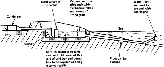
Sand can also be a hazard, especially if it is hard and sharp. Settling tanks are often used to take sand out of the system.
In such systems the water inlet is taken well out to sea. This usually avoids the areas of higher weed density. The inlet is kept well above the seabed to avoid intake of sand, yet well beneath the surface to avoid oil slick. Water inlet positions must be planned most carefully with all these factors in mind and with others, such as avoiding warm water from the discharge re-entering the system. The work involves a careful on-the-spot survey with seasonal observations. It usually entails a hydraulic model.
Power stations are often sited on rivers. In some estuaries the water may be seriously short of oxygen or have aggressive pollutants, which promote tube damage. In others, the water is warm through use by other power stations or may be in seasonal short supply. Cooling towers then become necessary. Their essential principle is shown in Figure 26.13. Warm cooling water is sprayed into the atmosphere within the tower and passes its heat to the air, which in turn becomes warm and rises. The tower is thus filled with air which is warmer than that outside and the thermal syphon effect creates a through-draught. Wind across the top of the tower can stimulate the process.
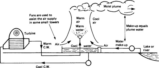
In a sea-water system the turbine exhaust temperature is set by the temperature of the sea plus the temperature difference required by the condenser to transfer heat. In cooling-tower plants a further temperature rise occurs because the air is normally warmer than the sea; thus the station efficiency is lower and the cooling plant more costly.
Some water is lost by a wet cooling tower. About 1.4% of the total throughput is carried away by the air—about 27 000 t/day for a 660 MW plant. At some sites a reasonable source of water is too remote for economic use and a dry cooling system must be adopted.
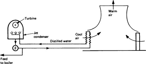
Figure 26.14 shows the principle of the dry cooling tower. There is no direct contact between the water coolant and air, so no water is lost. Cooling takes place in large heat exchangers at the base of the tower across which air is drawn either by natural draught or by fans. The cooled water, which must be pure enough to use in the boiler, is sprayed into the steam entering a jet condenser. Such a system was installed at Rugeley in England in 1961 as an experiment at 120 MW and others have been built overseas since. An alternative arrangement is to use a surface condenser instead of a jet condenser. Raw water is then used as a coolant instead of feed water.
The dry-tower system is less efficient than the wet because the terminal temperature differences are higher so poorer vacua are obtained. Also the tower itself is much larger and so the system costs more. It can, however, enable large amounts of power to be produced in a dry terrain.
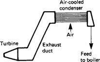
Where lower-power units are required, an air-cooled condenser (Figure 26.15) may be more economical than a dry tower. In the air-cooled condenser, the turbine exhausts to a heat exchanger mounted some distance above it. Steam goes through tubes and is condensed by air drawn or blown across them. The choice between air condensers and dry towers depends on many factors, but currently the former is used below about 100 MW and dry towers above about 200 MW.
26.2.4.2 Feed plant
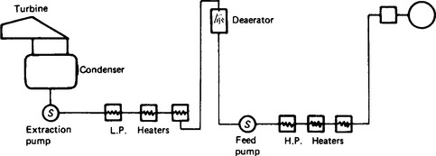
The feed water produced in the condenser is taken back to the boiler through a train of devices. First the extraction pump raises it to well above atmospheric pressure and drives the water through a series of l.p. heaters, which warm it with steam drawn from the turbine. The heaters are usually of tubular type, the direct contact type is out of favour after accidents in which water spilled back into the turbine.
After leaving the l.p. heaters, the feed water is lifted to the deaerator where it is mixed with more steam bled from the turbine, and releasing dissolved air that would otherwise appear in the boiler. Sometimes the deaerator is incorporated in the condenser itself.
Water is then passed through a network of further tubular heaters and the feed pump, before passing to the boiler via flow-regulating valves. A typical arrangement is shown in Figure 26.16.
The feed-heating system is complicated, expensive and often takes up almost as much station space as the turbine itself. In spite of the fuel saved by it (and even for a small station and medium steam conditions this can amount to over 10%) there is a trend to simplify by reducing the number of feed heating stages, more particularly on stations for developing countries where simple robustness is desirable and where fuel is not expensive.
The feed pumps of a large power station absorb considerable power—up to about 15 MW for a 600 MW generator. There is much to be gained by driving them in an economical way.
26.2.5 Turbine operation and control
There are two basic ways of arranging and controlling the steam supply. Where boilers have substantial storage volume in their drums, the steam is arranged to pass direct from the boiler to the turbine (Figure 26.17(a)). This is common practice in Britain. A system more frequently met overseas is Figure 26.17(b), which uses bypasses. This is essential for supercritical boilers, for no drum is used and the boiler has but little steam storage capacity. But the bypass system is also advantageous where only small drums are used. It allows the boiler to operate on part-load and pass steam via the bypass system to the condenser without its going through the turbine. Thus, should the turbine lose full load, rather than blow the safety valves the bypass will open and take steam from the boiler until the furnace heat has been adjusted to the load condition.
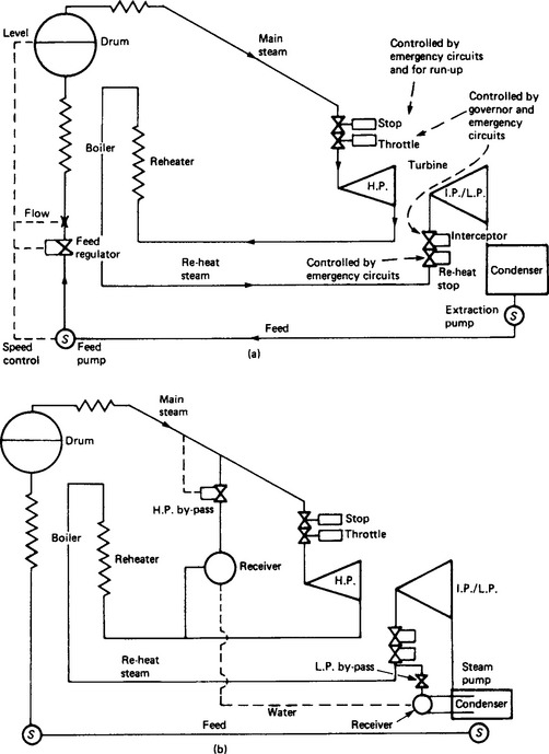
The bypass system has other advantages. For instance, the i.p. stage can be warmed through in parallel with the h.p. rather than in series with it, so applying hot steam sooner to the large i.p. cylinder and quickening the start of the unit as a whole.
When on-load in either system, the control of the turbine is by the governing system operating the throttle valves. Emergency signals of overspeed, oil loss, vibration, vacuum loss, etc., can close or reduce both stop and throttle valves by over-riding or acting through the governor. Instruments record the more important parameters of steam pressure, temperature, eccentricity, sliding, differential expansion, etc., and alarms operate from selected parameters.
Starting the machine is mostly automatic, or can be made so. There is a set sequence for taking each action, starting the oil system, barring the shaft, raising vaccum, etc. The most difficult operation and the one that requires most judgement is the admission of steam. The walls of the turbine valve chests and cylinders are thick and steam must not be admitted so quickly that severe thermal stresses develop. Many machines are equipped with instruments to measure the temperature difference across critical sections of chest or casing and so guide the operator on whether the warming through and starting is proceeding safely.
The operator must watch other factors too during a start. Most machines require special care to ensure that axial clearances are not taken up and these and the ease of sliding of the critical guidance and expansion surface are shown by appropriate instrumentation.
26.3 Gas turbine plant
During recent years many electric supply authorities have installed gas turbines, in unit sizes up to 150 MW, primarily for peak load or stand-by, but occasionally (where fuel is cheap) for base-load operation. Many industrial plants have also used gas turbines in connection with total energy schemes.
The major advantages of a gas turbine over steam plant are low capital cost, quick starting, small erection time and the facility for using a wide range of fuels from heavy oil to natural gas; also remote control or fully automatic operation is readily achieved. The disadvantages are the low thermal efficiencies (typically 25–30%) unless considerable complication is involved; the use of suitable materials to withstand very high temperatures combined with attack from undesirable elements in the combustion products is still a critical issue.
In the open-cycle plant, air is taken from the astmosphere, burnt with the fuel in a combustion chamber, passed through the turbine and finally exhausted to the atmosphere. In the closed-cycle plant air (or gas) is circulated around a closed circuit, heat being supplied to the air through a heat exchanger from an external combustion chamber. The former is the more common; its lower capital cost and adaptability to the relative importance of capital cost and efficiency are cogent factors.
26.3.1 Open-cycle plant
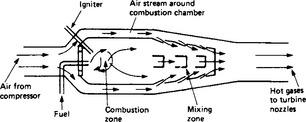
The simplest form of gas turbine consists of a compressor, a combustion chamber and a turbine as shown in Figure 26.18. This is the ‘single shaft’ gas turbine which is generally used for electricity generation applications. Driven by the turbine, the compressor delivers compressed air to the combustion chamber where there is continuous combustion of the injected fuel at constant pressure. In order that the temperature after combustion may not be too high, the ratio of fuel to air, by weight, is of the order of 0.017. This ratio is too low for combustion, so the air from the compressor is divided at entry to the combustion chamber. Part of it is used in the combustion zone and part acts as a coolant. The two streams are thoroughly mixed before entering the nozzles of the turbine at the permissible temperature. Figure 26.19 shows the outline of a gas turbine combustion chamber. The combustion of the fuel must be as nearly 100% efficient as possible to ensure a high plant efficiency and to reduce carryover of carbon matter to the turbine blades. The quantity of fuel injected controls the output of the plant but it is essential that flame stability shall be maintained over a wide range of fuel injection rates.
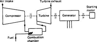
Figure 26.18 Simple open-cycle single-shaft gas turbine. Note that the turbine may also be split into high-pressure and low-pressure elements to form a two-shaft gas turbine
The heated air from the combustion chamber, including the products of combustion, is expanded in the turbine and is then exhausted to the atmosphere. Approximately two-thirds of the power developed by the turbine is used up in driving the compressor, the balance is used for producing the net output power for the generation of electricity or other purposes.
26.3.1.1 Simple power relations
Figure 26.20 shows the ideal pressure–volume diagram representing the ideal cycle work derived from the turbine and the ideal work necessary to drive the compressor. In practice the work done in the turbine is less than that for the ‘ideal’, i.e. the isentropic efficiency ηt of the turbine is less than unity. Similarly the work done in the compressor is greater than for the ideal case, i.e. the isentropic efficiency ηc is also less than unity. The useful work per unit mass of air is the difference between the work done by the turbine and the work required by the compressor, namely
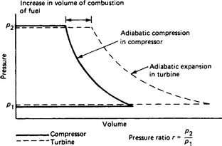
where k = r(γ − 1)/γ, r is the pressure ratio of compression and expansion, γ is the ratio of specific heats, cp is the specific heat at constant pressure, T1 is the absolute temperature at compressor inlet, and T2 is the absolute temperature of the air after combustion and before entry to the turbine.
It is evident that if ηt, ηc and T2 are too low this expression could have a negative value. The turbine output would not be sufficient to drive the compressor and there would be no useful work. Hence the success of the gas turbine depends on the attainment of high isentropic efficiencies in the compressor and turbine and the ability to operate at a high turbine inlet temperature.
The gas turbine must operate at very high temperatures to develop efficiencies comparable with those attained in steam turbines and diesel engines. The turbine blades must withstand both high stresses due to rotation and the high temperature of the combustion gases passing over them. The success of the gas turbine has been made possible by the development of steels which will permit stressing at high temperatures without excessive creep. To allow the use of higher gas temperatures the turbine blades are often cooled by fluid circulating through passages in them. The designed maximum temperature of operation is determined by the required ‘life’ of the turbine. A lower temperature of operation will reduce the creep rate of the stressed parts and increase the number of hours of running life of the turbine. Temperature gradients in rotors and blades also induce stresses and alternating stresses due to blade vibration could cause failure by fatigue. With the materials and design experience now available, efficient and reliable gas turbine plants are being built and many are in successful operation.
The gas turbine is not a self-starting machine; it must be brought up to speed by a starting motor until the compressor is running fast enough to attain an adequate pressure ratio and component efficiencies for a self-sustaining or viable cycle. After ignition of the fuel the machine will increase in speed until the turbine drives the compressor and provides the useful output. If the gas turbine drives a generator with separate exciter, the exciter may be used as a starting motor.
As in the operation of a steam turbine, starting up and shutting down must take place with due precaution to avoid excessive temperature gradients, particularly in the rotors.
Contemporary gas turbines have compressor pressure ratios (delivery pressure/inlet pressure) of as much as 30:1 resulting in combustion chamber pressures up to 3000 kN/m2 (435 lbf/in2 gauge).
26.3.1.2 More complex plant
The efficiency of the plant described above is somewhat low (25–30%). It has advantages of simplicity, low cost and independence of water. Higher efficiencies (30–40%) may be attained at the expense of greater complication and cost.
The addition of an efficient heat exchanger has a most pronounced beneficial effect on efficiency. Figure 26.21 shows a gas turbine plant in which a heat exchanger is included. Heat in the turbine exhaust is transferred to the air delivered by the compressor so that less heat is required from the combustion of fuel. The output of the plant is not increased but the reduction in the amount of fuel burned improves the efficiency. To justify its space, weight and cost the heat exchanger must have a high thermal ratio. It usually consists of a shell containing nests of small-bore tubes over which the turbine exhaust passes giving up heat to the compressor delivery air passing through the tubes on its way to the combustion chamber; however, heat exchangers have not been adopted widely for reasons of cost, bulk and reliability.
For electric power generation the gas turbine is essentially a constant-speed machine. The simple, single-shaft open-cycle gas turbine is not generally flexible as it needs to operate at full load at constant speed to give its highest thermal efficiency. Some flexibility is possible by adopting a ‘split shaft’ (sometimes known as a ‘two-shaft’) machine, but much better flexibility and performance can be obtained at the cost and inconvenience of complexity. There are many possible combinations of compressors, intercoolers, turbines, combustion chambers and heat exchangers. Figure 26.21 shows a plant in which the compressor and turbine are each in two stages. Interstage cooling of the compressed air increases the efficiency of compression. Another combustion chamber may be interposed between the h.p. turbine and l.p. turbine to increase the output of the plant. The separation of the turbine producing useful output from that driving the compressors makes the plant more adaptable to load variations with less reduction of efficiency at part load. The cost of more complex plant is, of course, justified only when the load factor and fuel costs are high.
26.3.1.3 Aircraft-type gas turbines
Since the 1960s there has been widespread application of aerojet gas turbines in which the propulsion jet is coupled to a heavy duty power turbine. The development of this type of turbine makes use of the extensive research carried out by the aero-engine industry and employs one or more aircraft jet engines to discharge into a gas turbine. Such units are reasonably inexpensive, compact and have exceptionally quick starting properties, e.g. full load from a cold start in 2 min.
The jet engine on aircraft has frequent skilled maintenance and normally operates at a high altitude with low atmospheric pressure. By de-rating the engine and incorporating certain small modifications it can be operated successfully at sea level at a power between its normal flight and take-off ratings and can give 20 000–25 000 h operation between overhauls. Its compactness also makes it suitable for mobile power plants.
26.3.1.4 Free-piston gas generator
Instead of the compressor and combustion chamber of the conventional gas turbine, one or more free-piston gas generators may be used to produce the hot gas for discharge into the turbine. This comprises a cylinder containing two free pistons; fuel is admitted between the pistons and, by compression ignition and appropriate operation of valves, hot gas is emitted from the exhaust ports. The chief advantage is a higher overall efficiency (30–35%) than the conventional gas turbine, but cost and maintenance requirements are generally greater so that applications are limited. A few successful plants of between 1 and 10 MW are, however, in operation.
26.3.2 Closed-cycle plant
In the open-cycle plant a continuous supply of air from the atmosphere is drawn into the compressor. The intake pressure and density of the air are, therefore, fixed at atmospheric conditions. By using the closed system shown in Figure 26.22, in which the same air is circulated continuously, the pressure and density of the air may be increased. More power is obtained from a given size of plant and output may be varied by changing the pressure and mass flow of air, the pressure ratio and speed being retained at the optimum values.
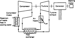
Combustion must be external to the air stream and the heat transferred to the air in an air heater. Waste heat is extracted from the system in a cooler placed before the compressor intake.
A further advantage of the closed-cycle plant is that the air is not contaminated by products of combustion and dust drawn in from the atmosphere. Other gases than air might be used if their physical properties were superior for the purpose, e.g. helium has been used for nuclear reactor cycles.
The main disadvantage of the closed cycle is the air heater. It is very difficult to attain high rates of heat transfer to a gaseous fluid like air, and excessively high tube temperatures are easily developed with consequent failure. Increasing the air velocity through the tubes improves the heat transfer but increases the pressure drop of the air in passing through the tubes. A similar problem occurs in the design of heat exchangers where improvements in heat transfer by higher velocities and greater turbulence result in excessive pressure drop. The solution is always a compromise between these conflicting factors.
26.3.3 Combined-cycle plant
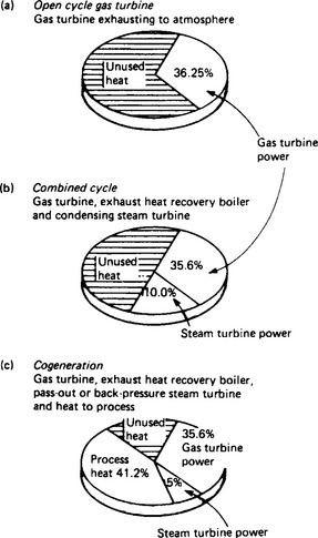
The combined cycle, in its conventional power generation form, recovers much of the gas turbine’s unutilised exhaust heat in a heat recovery steam generator (h.r.s.g.). The h.p. steam generated by the h.r.s.g. is used in a conventional Rankine cycle where the steam is expanded in a condensing steam turbine/generator set to provide an additional conversion of fuel energy to electrical energy. Unfortunately, because not all the exhaust energy can be recovered by the h.r.s.g. and the efficiency of the Rankine cycle is unlikely to exceed 38%, considerable energy is still eventually lost to atmosphere as low temperature heat, principally from the condenser. (The Rankine cycle thus acts as a bottoming cycle for the gas turbine’s higher temperature cycle.) Two typical arrangements are shown in Figure 26.23.
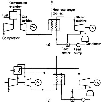
Figure 26.23 Gas/steam cycles: (a) simple cycle; (b) additional evaporator in the combustion chamber
Figure 26.24(b) illustrates the use of a high efficiency simple gas turbine in combined cycle mode. The situation has considerably improved and overall power generation efficiencies in the range 44–55% are currently available. Application is, however, still restricted due to the need for clean but expensive fuels such as distillates and natural gas. However, the above-mentioned application of fluidised bed combustion systems capable of burning all coal types, peat, refinery bottoms and cokes, is anticipated to change this. The increasing influence of emission controls also favour fluidised bed combustors which can absorb sulphur oxides (SOx) and produce inherently low-nitrogen oxides (NOx) without performance penalties. The addition of flue-gas scrubbers to conventional steam plant to absorb SOx and NOx causes a reduction in plant efficiency of 2–3 percentage points and 25–30% increases in capital cost. This will give a considerable incentive to utilities to give serious consideration to the new generation of fluidised bed combined cycles that are now available.
26.3.4 Cogeneration/CHP plant (see also Section 26.5.10)
If instead of using recovered exhaust heat solely for additional power generation in a bottoming cycle, it is used directly as heat for a process requirement, further substantial improvements in energy utilisation can be achieved. This is known as ‘cogeneration’ (of both heat and power), or sometimes as ‘combined’ heat and power (c.p.h.).
Figure 26.25 shows diagrammatically some of the heat utilisation forms that are possible with gas turbine cogeneration plant. In each case exhaust heat is used to eliminate, or significantly reduce the requirements for additional combustion of fuel in separate heat generation plant (boilers, kilns, combustors, fired heaters, etc.). In addition, since a number of the applications involve eventual heat rejection at temperatures close to ambient, most (if not all) of the exhaust heat can be credited to the overall thermal efficiency of the cogeneration plant. Accordingly, cogeneration installations can achieve very high overall efficiencies, up to 90%, depending on the nature of the heat utilisation.
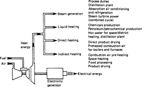
From the point of view of economically effective plant installations, the two most interesting forms of heat use shown in Figure 26.25 are the direct use of the gas turbine exhaust gases and the use of exhaust heat for steam generation. The first is of interest because no expensive intermediate heat exchange equipment is required to recover the exhaust heat; this possiblity arises because the gas turbine exhaust gases are relatively clean, particularly when the gas turbine is operating on high-quality natural gas, and they contain a large percentage of oxygen which can be used in further combustion processes downsteam of the gas turbine. Accordingly, the exhaust heat can be used directly for duties such as product drying or preheating of combustion air for product heating in fired heaters (petrochemical industry), kilns (brick and ceramics industry), coke ovens (steel industry), etc.
The steam generation function is of interest because it is often found that the steam is required at relatively low process pressures, say at an absolute pressure of 274–620 kPa. Since it is economic to generate steam in an h.r.s.g. at much higher pressures, say 1825–6310kPa, the opportunity arises to expand the steam from its generation pressure to the required process pressures using a back-pressure steam turbine, with steam extraction for intermediate pressure requirements. Thus, valuable extra electrical megawatts can be generated, thereby improving the economics of an installation, while serving the process steam requirement. Such plant would be properly referred to as combined cycle cogeneration equipment, although frequently only the cogeneration term is applied.
Figure 26.24(c) shows the energy utilisation of a typical combined cycle cogeneration plant. The figure shows that overall energy utilisation efficiencies well in excess of 80% can be achieved with this plant configuration. The performances of typical systems are shown in Table 26.6.
Table 26.6
TYPICAL SYSTEMS (simple-cycle, combined cycle and cogeneration)
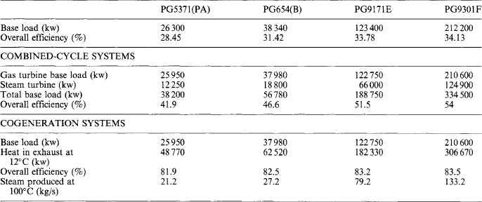
Basis for nominal performance ratings:
15°C, sea level, no intake or exhaust losses for open cycle, 245 mm H2O back-pressure loss in exhaust heat recovery systems.
Cogeneration systems are tailored for specific projects and the above examples are typical.
26.4 Hydroelectric plant
Hydroelectric plants convert potential energy of water into an electrical output. Rivers, upland lakes, coupled with their catchment areas, estuarial tidal cycles and upper reservoirs of pumped storage plants can provide the source of energy to be converted. The process involves flow of water from the source to the turbine tailrace, which acts as a sink. In the process of conversion, use is made of water turbines, of associated civil structures and of rotating electrical machinery.
The power supplied to the turbine, Pd (kilowatts) is given by the product of the rate of mass flow ζQ (tonne per second) and of the net head across the turbine Hn (meters) corresponding to this flow:
where ζ is specific mass (tonne per cubic metre) and Q is the volumetric discharge (cubic metres per second).
The net head (Hn) represents only a fraction, however large, of the total or gross head (Hg) which for all types of hydroelectric plant is defined as the difference in elevation between the water levels at the upstream (intake) and downstream (tailwater) limits of the installation, when there is no flow. The difference between these two heads represents the losses within the plant, but outside the confines of the water turbine. These losses are either due to flow related phenomena or arise because of the need to set certain types of impulse turbines well clear of the tailwater level. The ratio Hn/Hg is designated as the hydraulic plant efficiency (ηp) which, as will be shown later, can represent a significant parameter when evaluating the worth of alternative designs of the civil works.
While hydroelectric projects are normally considered in terms of the gross heads they create, water turbines are invariably designed bearing in mind the need to maximise the weighted efficiency at a number of net heads. Exploitable heads vary from a few metres to 2000 m.
It will be apparent that, even at the highest heads, the available energy levels per unit of mass flow, are substantially lower than those associated with thermal plants. Typically a conventional 660 MW thermal unit would require a water mass flow of 2000 t/h to achieve its full output. A similar rate of flow in a hydroelectric unit, operating at 2000 m head would produce an output of under 10 MW. At this flow, and at a head of 20 m, the output would be below 100 kW, the capability of a small mini hydroelectric unit. However, notwithstanding the very low levels of specific energy, high output per unit can be achieved, even at moderate heads. This clearly involves very high rates of mass flow.
The greatest outputs, on modern units, have been achieved at net heads of around 120 m where flow rates of 700 t/s yield outputs of 715 MW. Similar rates of flow have recently been considered on some very low head, tidal installations, currently under study. These would result in outputs of 40 MW or so. In the former case, the diameter of the water turbine runner is 8.5 m; in the latter case a 9.0 m runner is envisaged. The largest runner diameter already in service is believed to be 9.3 m. It will be appreciated that machines of these sizes would operate at very low rotational speeds. The 715 MW units operate at 90.9 and 93.3 rev/min on the 50 and 60 Hz systems of Paraguay and Brazil, respectively.
The proposed synchronous speed of tidal units amount to only 50 rev/min and even that speed represents a compromise between the optimum speed of the turbine for energy capture (47 rev/min) and the need to ensure that the generator design parameters, such as the number of poles and the rating, could be achieved without recourse to the use of an uneconomical, oversized rotor. It is the quest for higher rotational speeds and for higher turbine efficiencies which provides the motivation for the continuing development of turbine designs.
26.4.2 Types of plant
The very wide range of possible operating conditions has led to the development of a number of diverse designs of rotodynamic machinery. However, as far as the conceptual design of plant is concerned, there are in the main only two basic types of arrangement of the powerhouse within the scheme; there are, of course, some variations on the theme.
One of these arrangements is known as a ‘run of the river’ plant (see Figure 26.26). Here the powerhouse is either incorporated in the dam, or is located alongside it, i.e. is local to the dam. In such an installation, the gross head is determined by the difference in levels across the dam. The majority of such installations operate at heads of less than 100 m. However, even substantially higher heads, amounting to 200 m or so can be accommodated with this arrangement, as evidenced by the example of the Boulder Dam in the USA. This arrangement is also employed on tidal schemes, where the gross heads involved are well under 10 m.
Figure 26.26 A ‘run of the river’ plant (Boguchauy hydroproject). (a) Layout: 1, powerhouse; 2, spillway; 3, rockfill dam; 4, switchyard. (b) Section through the dam and centre line of a unit
The alternative arrangement is known as a ‘diversion’ plant (see Figure 26.27). Here the supply is taken from a dammed river or lake, from which water flows through a head race canal to a head pond or forebay in the vicinity of the remote powerhouse. From the forebay, the water flows to the turbine through a system of pressurised pipes, known as penstocks. The purposes of the forebay is to ensure that sudden changes in rates of flow, dictated by turbine controls, can be accommodated without producing unacceptable changes of the levels in the canal. In a variation on this design, the canal is replaced by a low pressure tunnel. In such a case, when control considerations justify it, a surge chamber or surge tank is provided.
The purpose of either of these devices is to protect the low-pressure tunnels from water hammer caused by turbine controls and to permit quick starts of the turbine, without producing significant loss of head, caused by the need to accelerate quickly the water column within the tunnels.
The powerhouse in a diversion-type plant may occasionally be located underground. Here, the tailrace may take the form of a tunnel. In cases where the tunnel runs full and is of sufficient length for the effect of the inertia of the water column to become significant a surge chamber may have to be provided downstream of the turbine draft tube. Thus it is possible to have plants of this type with no surge protection or with one surge chamber upstream or downstream of the plant or, alternatively, with two surge chambers or tanks.
Finally, in micro units which, because local demand for power is limited, may take only a fraction of the total discharge of a river, it is often possible to divert sufficient flow without the use of a dam, simply by providing a parallel channel.
Thus, it will be noted that in diversion plants the gross head is either only partly or not at all dependent on the level above the toe of a dam. In any case, a large proportion of the gross head, even in a system containing a dam may be due to the geodetic head difference between the toe of the dam and the tailwater level. Thus a diversion type of plant makes it possible to create high heads without the need to build tall dams.
Another important aspect in the consideration of the design of hydroelectric plant is concerned with the question of how best to develop the potential of a river or a basin. Given the statistical information concerning the ‘run off’ over a period of many years, the designer must consider the various ways in which the potential can best be exploited. The local load demand and its probable rate of growth must also be taken into consideration.
Where the hydraulic potential is large but the local demand is small or even non-existent, the designer must consider the viability of transmitting large amounts of power to distant load centres, as was done in the cases of Churchill Falls in Labrador (the power output of which is exported to the USA) and Cabora Bassa in Mozambique (which was constructed on the assumption that it would export power to South Africa). Yet another possibility is presented when a substantial load such as an aluminium smelter can be brought to the vicinity of the plant, as was the case on the Volta River in Ghana.
Where a scheme is to meet a demand which is expected to grow substantially with time, economic considerations dictate that, if at all possible, the scheme should be built in stages. Where damming of the source of power is involved, this of course must be done before any power at all is produced. It is possible, however, to install only the amount of machinery commensurate with the initial demand. Alternatively, a scheme may be evolved for using only a portion of the total potential head by dividing the overall scheme into a number of stations to be developed sequentially.
Another aspect of conceptual design concerns the case of a potential site where the available gross head is substantial, the site topology favourable, but the ‘run off’ insufficient to support the required levels of output. In such a case, diversion of ‘run off’ from neighbouring catchment areas through low-pressure tunnels is often employed. Only when the flow-duration data including normal seasonal variations and effects of unusual dry and wet years has been established and the storage capacity determined can the most economic mode of operation be considered. In addition, the existing load demand and its anticipated rate of growth must be taken into consideration.
Where there is no storage capacity or where the storage capacity is only small, the output, up to the rated capability of the plant, will tend to be in step with the flow. At times of flood, excess of flow over that used for generation must be spilt over the dam. Even in such a plant, it may often be economical to increase the capability of the rotating plant well in excess of the rating based on time averaged rates of flow. This is so because the cost of the civil works represents a major component of costs and the marginal increase in costs arising as a result of the use of oversized rotating plant could be more than compensated for by the value of the additional energy recovered during the period of floods.
Where the inflow to a scheme is seasonal, as is typically the case where melting of snow or of glaciers is the source of water, provision of storage capacity is essential. Where storage capacity is provided, it is not only possible, but often very desirable, to increase the capability of the plant well beyond that corresponding to a plant that would operate on a base-load principle. This is due to the fact that hydroelectric plants are inherently suitable for use as peak-lopping plants. Where pondage is small, this type of operation can be achieved by providing a pumping facility for replenishing the stored energy. On any but the very high-head plants using impulse machines, the ability to operate both as a pump or as a turbine can be achieved in a single reversible pump-turbine unit. During pump operation the generators would operate in the motor mode. From the foregoing it will be clear that in the majority of hydroelectric plants the rated capability of the plant does not relate directly to the firm volume of output. While steps can be taken to reduce seasonal variations by provision of storage, the main uncertainty stems from variations in precipitation, be it in the form of rain or snow.
It is therefore desirable to install either a suitable mix of schemes or to ensure a certain level of stand-by capacity in thermal plant. Only very occasionally, on small schemes, taking their supply from large natural lakes, can the rated capacity, with suitable allowances for outages, be taken as firm power.
26.4.3 Power station
Depending on the layout of a scheme, the turbines, their auxiliaries and the electrical plant may be housed either at or below ground level. Run of the river situations are invariably housed at ground level and are located either inside or alongside the dam. On very low head schemes they may be housed within the structure of a submerged weir, with provisions for spilling excess flow, over the roof and side of the station. In diversion schemes, the power station is housed either in a purpose-built structure at ground level or in an underground cavern.
By comparision with thermal stations, the number of auxiliary systems that must be housed either within, or in the vicinity of, a hydroelectric power station is fairly limited. Such systems that are essential include the following:
(1) Gates and/or valves used for isolating the turbine, together with the associated pumping sets and pressure receivers. Note that closure must be effected either under the action of gravity or by utilising stored energy.
(2) Governors, actuators and servomotors and a power oil system containing sufficient stored energy for operation of a closing–opening–closing cycle.
(3) Duplicated de-watering system with a proportion of the de-watering pumps supplied from a secure battery based supply.
(4) A compressed-air system capable of charging and topping up the pressure receivers under (1) and (2). Where synchronous condenser operation is involved or where pump turbines are employed, the compressed air system should have sufficient stored capacity to permit the blow down of one unit at a time and have the additional capacity to make up air losses following the blow down.
(5) Cooling systems for generators, transformers, pumping sets and for thrust and journal bearings of the turbogenerator.
(6) A heating and ventilating plant capable of maintaining the required degree of comfort.
(7) Voltage regulators and controllers.
(8) Instrumentation and controls for monitoring and operating the units and their auxiliaries, including automatic synchronising equipment.
In addition to the generators, the electrical plant housed within or in the neighbourhood of the plant consists of low-and high-voltage switchgear, transformers and generator bus-bars. In connection with the latter it should be noted that, as the generator voltages employed in hydroelectric sets tend to lie in the range 8–15 kV, considerations of the cost of bus-bars dictate that the main transformers must be placed in close proximity to the generators. Thus in underground stations the main transformers are normally housed in galleries running alongside the turbine hall.
On installations on which large pump turbines are employed, pump-starting equipment has to be housed within the stations. This equipment operates on the variable-frequency principle and comprises transformers, converters and inverters, together with the associated switchgear, controls and bus-bar connections. The use of a de-watered pump turbine ensures a soft start prior to synchronising with no significant surge currents.
26.4.4 Turbines
Consideration of hydraulic conditions at the turbine runner leads to the division of water turbines into two main groups: the impulse turbines represented in modern turbine practice mainly by Pelton wheels; and reaction turbines, a group covering both mixed flow and axial flow machines.
Impulse turbines are driven by jets of water issuing from one or more nozzles distributed tangentially around the periphery of the wheel. The power output is controlled by adjusting the opening of the nozzles. As such adjustment does not affect the direction of the jet, the part-load performance of such machines is on a par with that at the design point.
With a few exceptions, reaction turbines are normally equipped with movable guide vanes. These are disposed symmetrically around the runner and control both the velocity of flow and its direction at the entry to the runner. The majority of reaction turbines have runners whose geometry is fixed and invariable. Modern, mixed flow machines, equipped with such runners are known as ‘Francis’ turbines. The flow at inlet is invariably inward and the flow at exit is usually axial. The axial-flow machine with a fixed geometry runner is known as a ‘propeller’. Turbines in which the guides are movable but the runner blades are fixed are said to have ‘single regulation’. Part-load performance of such machines (see Figure 26.28) tends to be poor. In order to improve performance, machines with both movable guide and movable runner blades have been introduced. Such machines are said to have ‘double regulation’.
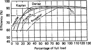
Axial-flow turbines with double regulation have been employed since the 1920s. They are known as ‘Kaplan turbines’, after their inventor. Double regulated mixed-flow turbines have been used since the 1950s. This type of turbine is now designated as either a ‘diagonal’ or a ‘Deriaz’ turbine, after its inventor. It may be of interest to note that the Deriaz turbine was first developed in Rugby, England. Perusal of Figure 26.28 will show the degree of improvement, of part-load performance, resulting from the use of double regulation, on both axial- and mixed-flow machines. It will be appreciated that double regulation increases both the size of a machine and its costs. However, the resulting improvement in performance under a range of operating conditions can make their use economically justified, either where single or very few machines are installed, or where substantial head variations are encountered.
The range of heads for which the various reaction machines operating as turbines and as pump turbines are suitable is shown in Figure 26.29 This figure also indicates the outlines and the proportions of the runners of such machines. The shape of runners corresponding to progressively higher heads are shown from left to right.
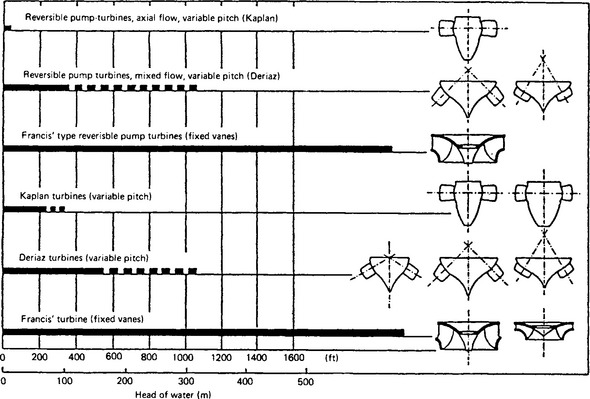
With the advent of physically large units operating at very low and varying heads, as encountered on some run of river schemes and on tidal applications, yet another variation on the design of an axial flow turbine has been introduced. This type of turbine, known as a ‘Kapeller’, has fixed guide vanes but the runner is equipped with movable runner blades. Such a combination produces a plateau of relatively high turbine efficiencies, along the line of maximum output for a substantial range of heads.
In an impulse turbine all the available energy is converted into velocity, before the water enters the runner, while in a reaction turbine the process of conversion takes place partly before and partly after the water has entered the runner. The division of water turbines into these two groups is based on general usage and does not imply any difference in the method of energy transfer between the water and the runner. At its simplest the principle of a water turbine is that of a rotating duct, through which flows a stream of water. The stream and the duct interact; the stream is deflected and, as a result, a force is exerted on the duct. The moment of this force, about the axis of rotation of the duct is equal and opposite to the change in the moment of momentum of the stream. If the mass of water, flowing in a unit of time is ζQ, the driving torque M is given by
where Cu1 and Cu2 are the whirl velocities at the inlet and exit, and r1 and r2 are the corresponding radii. Note that only the whirl components of the absolute velocities of flow contribute to the driving torque.
The driving torque can also be determined from considerations of power output from the turbine and of angular velocity ω. Hence it can be shown that
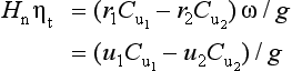
where u1 and u2 are the peripheral velocities of the runners at the inlet and exit, and ηt is the turbine efficiency.
If the effect of the small mechanical and volumetric losses on turbine efficiency is neglected and the concept of effective head He = Hnηt is introduced, we get the Euler turbine equation in its canonical form
This equation demonstrates the interdependence between head, velocities and the geometry of the turbine, at entry and exit from the runner.
It should be noted that, although equations (26.4) to (26.6) are constantly used in the literature to describe the performance of water turbines, they are only strictly applicable to machines in which the flow can be fully described by a single representative stream line.
26.4.4.2 Fundamental similarity
Turbine characteristics are normally established on the basis of tests carried out in hydraulic laboratories on homologous models of the machine and of certain associated water passages, be it distributor pipework and nozzles in the case of a Pelton wheel, or a portion of the inlet pipe, the spiral casing and the draft tube in the case of a reaction machine. For the model to be homologous it must be:
(1) geometrically similar—the requirements are that if any representative dimensions defining a water passage are in a given ratio, then all the dimensions of the units must be in the same ratio, i.e. Da/Db = Dma/Dmb = constant; and
(2) kinematically similar—i.e. it is necessary for all the fluid velocities to change in a given ratio when going from one system to a corresponding point of another. This requirement can be expressed mathematically as
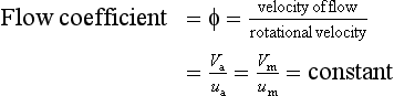
The above relationships can be expressed in the form
where n is the rotational velocity and D is the diameter of the runner. In addition all the fluid velocities must have the same direction at similarly located points. These two conditions can be summarised by stating that all the velocity triangles at all corresponding points must be summarised by stating that all the velocity triangles at all corresponding points must be similar.
(3) dynamically similar—i.e. any forces, be they inertia, viscous in origin or those arising out of cavitation phenomena, acting at similar points of fluid should have corresponding magnitudes and should be so arranged that the ensuing flow can satisfy the conditions of kinematic similarity and follow similar paths.
In order to meet these conditions, in machines operating at speeds which are inversely proportional to size it is necessary to ensure that Reynolds numbers for both the model and the prototype are sufficiently high to assure similarity of viscous forces. In addition, the consistency of head coefficients (ψ) at corresponding points must be assured. This last requirement can be expressed mathematically as
Using the relationships established above, and if small differences in the respective prototype and model efficiencies are disregarded, it is possible to derive a number of parameters in terms of which the performance of a whole family of homologous machines, of various sizes and operating at differing heads can be reduced to just a single diagram, applicable to the whole range of similar turbines. This is achieved by reducing all the data to those appertaining to a turbine with a runner of unit diameter, operating under unit head. These parameters are:
In the case of turbines, the performance is nowadays most commonly expressed in terms of unit speed against unit quantity, with efficiency curves (mussel curves) superimposed on the diagram. Occasionally, cavitation data are also superimposed. In the case of pump turbines the above diagrams would normally be extended to cover both turbine and pump operation. In addition, a four-quadrant plot of unit speed against unit torque is often given.
Typical turbine characteristics for a high-head Francis and a propeller turbine are shown in Figures 26.30 and 26.31. Figure 26.32 shows a four-quadrant characteristic for a reversible pump turbine.
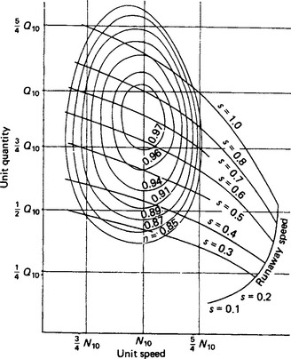
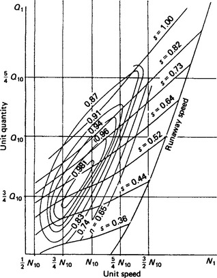
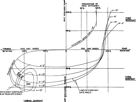
26.4.4.3 Specific speed
In order to extend codification of hydraulic performance from that covering just one family of homologous turbines at a time to all turbines at large, it was found necessary to introduce yet another parameter. Theoretically, this parameter, known as ‘specific speed’ (Ns), should be obtained by combining unit speed and unit power at the point of best efficiency (b.e.p.) in such a manner as to eliminate the size of the unit from the resulting expression
However, the published data are more often than not based on the value of this parameter for the rated output rather than the b.e.p.
It should be noted that specific speed is a dimensional quantity and, therefore, the system of units must be specified. Thus in SI units, speed (n) is in revolutions per minute, power (P) is in kilowatts and head (Hn) is in metres. Unfortunately most of the available data are classified in terms of specific speed expressed either in metric or British units. In both systems, the horse power is taken on the reference unit and heads are in metres or feet, as appropriate. Thus, when referring to such data, it should be borne in mind, that
Whichever system of units is used, the numerical value of the specific speed represents the rotational speed at which a homologous machine would operate if it were designed to give an output of unit power, under unit head, when operating in the same fluid and at the same efficiency.
At this point, it should be mentioned that, while machines having different specific speeds cannot be geometrically similar, it is possible for machines of the same specific speed to be geometrically different, because the same hydraulic conditions can be met by different designs. Thus at certain ranges of specific speed there are overlaps between machine types. The two such ranges of interest concern the overlaps between Francis and multi-jet Pelton wheels at the lowest specific speeds and between Francis and propeller turbines at the highest specific speeds corresponding to the Francis range.
In selecting an appropriate specific speed for large reaction turbines of a particular installation, use may be made of a number of empirical expressions which summarise the current achievements world-wide. These expressions are normally given in the form
where A is a constant whose magnitude has been steadily increasing with the passage of time, following the adoption of higher specific speeds.
In the case of major reaction machines this constant is now taken as 2400 or so. Some 25 years ago, on Francis units US practice was based on half of this value. This improvement was made possible by better understanding reached through research and testing of the conditions at the turbine runner, where the danger of damage by cavitation represented the major risk. The steady increase in the magnitude of this constant represents a substantial economic benefit because the higher specific speed leads to smaller runner diameters and higher running speeds.
In the case of impulse machines the specific speed is based on a per-jet principle. Thus if a wheel is equipped with four jets its specific speed would be twice that of a wheel with just one jet. The range of specific speeds covered by Pelton wheels equipped with a single jet extends approximately from 10 to 80 rev/min, the lower figure corresponding to the highest available heads.
Because of the overlap between Pelton wheels and Francis turbines, the choice of machine type for a given combination of head and flow becomes too complicated to be expressed by a simple formula. Instead, the reader is referred to Figure 26.33 which demonstrates the design trends.
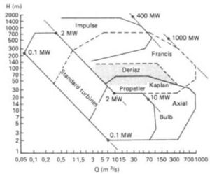
For many years specific speed has been used as a general guide to the shape, relative size and speed of machines. It also provides access to information regarding typical efficiencies, flow and head coefficients as well as to values of runaway speeds appropriate to a given class of machinery. The relevant information is summarised in Figure 26.34.
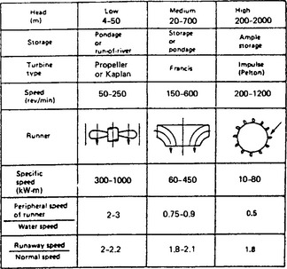
26.4.5 Hydrogenerators
Because of the system frequency, the maximum design speeds encountered in practice are not greater than 1000 or 1200 rev/min and salient-pole generators are almost universally employed. Small induction generators of up to 5 MW are used in isolated cases. The two requirements specific to hydroelectric installations are the need to take into consideration the very high runaway speeds and the need to provide sufficient rotary inertia to assure both the quality of speed control of the turbine and the stability of the electrical system. In the case of vertical-shaft units the specification often calls for the bore of the generator stator to be of sufficient size that the turbine runner can be withdrawn without the need to remove the stator. Thrust bearings are normally provided on the generator shaft. It is thus necessary for the generator designer to be acquainted with the magnitudes of hydraulic thrusts appertaining to a range of operational conditions.
As a result of the restrictions on size and weight due to consideration of transport and access to remote sites, generator rotors and stators are often assembled on site using preformed, transportable components. In the case of major schemes it is often economic to construct a dedicated factory at the site of the scheme, rather than to transport large components and subassemblies to the site.
26.4.6 Economics
The capital costs per unit output of hydroelectric schemes are normally very much higher than comparable costs for thermal stations. This is due to the cost of the extensive civil-engineering works involved and to the very long periods of construction, during which costs are incurred and interest has to be paid, without receipt of any compensating income. However, the civil works are permanent and the life of much of the plant may well be 60 years between major overheads, partly because of its durability and partly because the problem presented by obsolescence hardly arises. Operating costs are very low, comprising only taxes, wages and salaries of the staff and low levels of expenditure arising from the need for maintenance of the plant. Because a very large portion of the lifetime costs is incurred before a scheme is operational the cost of borrowing is one of the major parameters to be considered when assessing the viability of any scheme. As a result, the construction of many power-producing schemes can only be justified by incorporating them within larger schemes producing additional benefits such as irrigation, flood control or navigation.
The cost of the environmental effects of a scheme cannot be easily assessed. Hydroelectric schemes often provide excellent recreational facilities, first-class roads and river crossings. However, they lead to drowning of valleys, interfere with the migration of fish and can lead to the deposition of substantial amounts of silt upstream of dams. Tidal schemes can badly affect the ecology of an estuary, especially during the construction period, and on any future schemes it will be necessary to ensure that at no time will a tidal reach of a river be turned into a temporary sweet water or brackish lake.
Notwithstanding the difficulties arising from the need to assess the ecological consequences of major power schemes, their effects must be seen to have been taken into account in any assessment of the viability of any future scheme. Otherwise, major costs will be incurred by the population at large rather than the polluter.
26.4.7 Pumped storage
26.4.7.1 Historical development
In many countries the available water-power resources are becoming fully utilised and, as environmental considerations lead to resistance to further encroachment by developments leading to the inundation of large tracts of land, modern hydroelectric practice is tending towards construction of pumped storage schemes. Currently some 20% of the world’s largest turbines are used in this mode.
The location of such installations is not critically dependent on the quality of the catchment area, but there must be sufficient water to fill and make good any losses due to seepage and evaporation. However, any natural inflow to the upper reservoir produces a bonus in output.
As the cost of machinery per unit output depends on the available head, there is an incentive to construct such schemes at sites providing potential heads in the range 300–600 m. Should such sites not be available, lower heads could still be exploited, but at a greater cost. The pump turbines employed on schemes with heads of up to 600 m would nowadays invariably be of the single stage, reversible type. Where higher heads are encountered, the pump turbines would employ several stages of runners/impellers. Alternatively, the scheme itself can be based on the use of two or more pump turbines operating in series. However, such a solution would involve substantial additional costs.
Wherever possible, the existing storage capacity of conventional hydroelectric plant is used as the base for the pumped-storage plant. In the absence of such facilities, large existing underground excavations may be used as the lower reservoir with the pump turbines installed in a deep shaft, well below the free level of the underground reservoir.
Historically, on pumped-storage schemes separate pumps and turbines were employed with the generator doubling up as a motor in the pumping mode. The four 90 MW units operating at a maximum head of 320 m installated at Ffestiniog, North Wales, are typical of this type of installation. All the machinery is arranged in line and the length of the main shaft is around 30 m. When pumping, the turbine is run in the dry and the thrust load is supported on two separate thrust bearings, one of which is located within the generator and the other under the pump. A coupling is provided between the turbine and the pump. Separate water conduits lead to the turbine and the pump and these are guarded by separate sets of valves (see Figure 26.35(a)). In 1960, when the scheme was commissioned, Ffestiniog was the largest pumped-storage project in the world. Even at the time, the design concept was already obsolescent. The next generation of pumped-storage plants depended on the use of reversible pump turbines which were developed at that time. Figure 26.35(b) demonstrates the simplification of layout arising out of the use of reversible units.
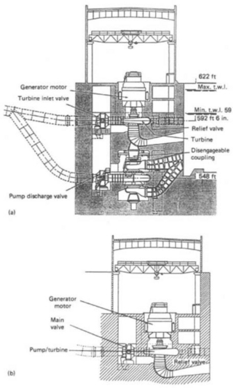
Figure 26.35 (a) Section through the pumped-storage station of the Ffestiniog site, North Wales. (b) Possible arrangement of a reversible installation based on the Ffestiniog site
In Great Britain, because of constraints imposed by the terrain, conventional hydroelectric installations provide a very small fraction of the electrical output. Such schemes as are in existence are invariably small and are mainly located in the north of Scotland. However, there is a substantial investment in pumped storage. In addition to the 360 MW installation at Ffestiniog, there is a four 100 MW turbine installation at Loch Awe, operating at a maximum head of 365 m; a two 150 MW turbine installation at Foyers, Loch Ness, operating at a head of 180 m and the six 300 MW turbine station at Dinorwig, North Wales, operating at a maximum head of 545 m.
At the time of writing, the reversible pump turbines giving the largest output are installed at Bath County, USA, where six 457 MW units operate at a maximum head of 329 m. Next in terms of output come the units at Helms, USA, operating at heads of up to 540 m with an output of 400 MW per unit. Comparable outputs are obtained at Racoon Mountain, USA, where the operating heads are 310 m.
At the heads beyond the range of Francis turbines, where Pelton wheels are employed, application of pumped storage involves the use of multistage centrifugal pumps. Because of the need to ensure that the Pelton wheels are set above tailwater level, while high-head pumps require substantial submergence, the generator can no longer be used to drive the pump.
The Roncovalgrande plant in Hago Delio, Italy, operating at a maximum head of 747 m is equipped with eight Pelton wheels and a single pump. Similar arrangements have also been used at San Fiorano, Italy, where four Pelton wheels and one pump are installed. These operate at heads in excess of 1400 m.
Yet another solution to the problem presented by pumped storage at high head is presented by the use of multistage reversible pump turbines. An example of such an application is provided by the Edolo plant in Italy where eight such machines each rated at 132 MW operate at a head of 1287 m. In connection with the use of such machines it should be mentioned that, while their performance at or about the design point can be excellent, their output cannot be varied other than by natural changes in head. However, with eight units installed, the output of the scheme can of course be varied in stepwise fashion between 12.5 and 100%.
26.4.7.2 Mode of operation
Pumped storage plants provide the means for system regulation, peak lopping capacity and spinning reserve. Where a correct mix of thermal stations and pumped-storage plant has been installed, the system operator can maintain continuous output from base-load plant even at times of low-load demand. At times of high-load demand, the pump turbines provide additional output, and when operated in the spinning reserve mode they are capable of very quick response to system demands. Their use, unlike that of conventional hydroelectric units, does not in the main introduce the utilisation of renewable energy. Their economic and operational benefits arise mainly from a reduction of the high costs incurred in both fuel and in the consequences of physical damage incurred by thermal stations when operated in a cycling mode, such as ‘two shifting’, so common in the UK and elsewhere. They also ensure that the uneconomic use of gas turbines in their peak-lopping mode of operation is no longer necessary, thus removing the need for the provision of such facilities.
The rapid response capacity of pumped storage plant can be seen from consideration of the operating times, under automatic control, achieved at the Dinorwig power station:
(1) standstill to no-load generation 90s;
(2) no-load generation to 1320 MW station output 10 s;
Modern reversible pump turbines when starting in the pump mode are nowadays run up to speed and synchronised while the generator that acts as a motor is under the control of static, variable-frequency convertors. These convert the fixed voltage, mains frequency supply into a variable voltage, variable frequency output. Fixed-blade machines are normally started with the runner operating in the dry, in compressed air. Movable-blade runners are normally started with the unit watered, but with the blades fully feathered, to minimise resistance.
Starting a set for generation simply involves, after starting the essential auxiliaries, admitting water to the turbine. Where separate pump and turbine units are installed, like at Ffestiniog, the start of pumping involves: running the set up to speed by the turbine and then synchronising; closing the turbine guide and inlet valves so that the set is motoring; dewatering the turbine casing using compressed air; and opening the pump discharge valve. At Dinorwig changeover times from pumping to turbining under normal procedures take just under 10 min. In an emergency this time can be reduced substantially. It is claimed that at Dinorwig under an emergency procedure the changeover can be achieved in 90s. The changeover from turbining to pumping is much slower, mainly because the rates of acceleration of the unit in the pump start mode are controlled by the capability of the static, variable-frequency converter. However, as already pointed out, the initial reduction in load, from full to no load, is only a matter of 10 s or so.
26.4.7.3 Economics of pumped storage
The overall energy efficiency of a modern pumped-storage scheme is usually about 75%; the losses arise chiefly from the need for double energy conversion and from loss of water from the upper reservoir due to seepage and evaporation.
The running costs of the station comprise the cost of the energy used in pumping (including the above losses), wages and maintenance, and the costs of transmission losses arising from the remoteness of the station. Pumping energy can be purchased at off-peak times at between one-half to two-thirds of the price at which it can be sold at times of high demand.
Capital costs depend critically on the topography of the site and on the availability of efficient turbo-machinery of sufficiently high specific speed. The latter determines the size of the power station and the cost of generators.
Availability of pumped storage increases the efficiency of operation of the whole interconnected system and, because of its rapid response capability, removes the need for investment in gas-turbine based peak-lopping units and of operation of thermal units in the spinning reserve mode. Given the correct mix of pumped storage and thermal stations, the need for two shifting is largely eliminated.
In Europe, the USA and Japan, many pumped-storage plants have been built. Many more are projected or are in the course of construction. Pumped plants comprise the single most important area of growth of hydroelectric power generation.
26.5 Diesel-engine plant
Generators powered by diesel engines are employed in three main roles:
(1) on primary or base-load duty in locations where there is no utility supply or as an independent power source to ensure security of supply where a public supply system is available;
(2) for peak-lopping (or peak-shaving) duty to supplement and/or reduce the cost of supply from a utility source; and
The speed of crankshaft rotation basically determines the weight, size and cost of an engine in relation to its output power. Engines are generally accepted as being divided into three classes:
The maximum size of diesel plant for primary power generation is for all practical purposes between 150 and 200 MW per station. Output ratings available are in unit sizes from 1 kW to 30 MW. The most significant range for generating plant in all three utilisation categories (continuous, peaking and stand-by) lies between 250 kW and 3.5 MW unit sizes, in the medium- and high-speed classes.
The choice between low, medium or high speed engines must be related to evaluation of power supply security against operational economy. Security of supply is essentially a function of the availability of engines and the number of units and spare capacity installed in relation to the average load demand.
26.5.1 Theory and general principles
The compression ignition engine operating on liquid fuels, or in the dual-fuel mode, works on the principle of fuel being injected into a charge of compressed air and spontaneously ignited by the high temperature of the induced air by the heat of compression. The process converts the heat energy of the fuel into mechanical work.
The two basic working cycles are four-stroke and two-stroke. These are represented diagrammatically in Figures 26.36 and 26.37 together with the appropriate indicator diagrams, which portray the events within the engine cylinder during each cycle.
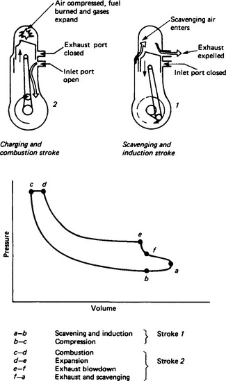
In the two-stroke engine the working stroke occurs in each revolution of the crankshaft, whereas in the four-stroke engine it occurs once in every two revolutions. It does not follow that, because the two-stroke engine has twice as many power strokes as the four-cycle engine it will produce twice the power. The down stroke of the two-cycle engine (Figure 26.37) combines both power and exhaust strokes. As the intake and exhaust ports are cleared by the piston some mixing of fresh air charge and burned gases takes place (scavenging). Not all the burned gases are exhausted, which prevents a larger fresh charge of air being induced into the cylinder. The resulting power stroke has, therefore, less thrust.
In the four-stroke engine, however, nearly all the burned gases are forced out of the combustion chamber by the up-stroking piston. This allows almost a full air/fuel mixture to enter the cylinder since a complete piston stroke is devoted to induction of the mixture. The power stroke therefore produces relatively more power than its two-cycle counterpart.
26.5.1.2 Combustion
The major advantage of the reciprocating internal combustion engine is that its design is not limited by the properties of the materials of its construction, since none of its parts is required to work continuously at maximum-cycle temperature. This allows high maximum-cycle temperatures to be used, which results in a high thermal efficiency—this is a measure of the efficiency with which the fuel is burned during the combustion process to produce engine power.
Whilst compression-ignition engines are generally about 5% more efficient than their prime-mover competitors, there is appreciable variation amongst them in thermal efficiency. Much depends on the size of engine and the type of combustion chamber.
Combustion chambers are basically of two types: those designed for indirect injection and those for direct injection. The former employ pre-combustion chambers in the cylinder head into which a relatively coarse fuel spray is injected at low pressure. They are popular with European and American engine manufacturers and have the advantage of being able successfully to handle a wide range of fuels. When required to operate over a wide band of environmental conditions, however, they compare unfavourably with direct-injection chambers on fuel-consumption performance. Also, since heat loss from the pre-combustion chamber is high, cold starting can be difficult without prolonged cranking or recourse to external heating (such as glow plugs).
In direct-injection systems the underside of the cylinder head is usually flat and clearance volume on compression is mainly contained within the piston crown. Crown depressions are so shaped as to effectively induce swirled air turbulence, as the piston rises on its compression stroke. Fuel is then injected in the same direction as this flow of swirling air. The direct-injection principle is almost universally employed in modern medium-speed and on many high-speed engines.
Small-bore engines tend to have lower thermal efficiencies because their high surface-area/cylinder volume ratios give larger heat losses. Again, the greater heat losses from the larger exposed surfaces of indirect-injection systems means that they give lower thermal efficiencies than direct-injection ones. For these reasons, small indirect-injection engines may have thermal efficiencies as low as 28% whilst larger engines, particularly those using direct-injection techniques, may have efficiencies as high as 40%.
26.5.1.3 Pressure charging and inter-cooling
In the naturally aspirated four-stroke engine the working cylinder is almost (but not fully) charged with fresh air at atmospheric temperature and pressure at the end of the suction stroke. The density of this aspirated air regulates the weight of fuel which can be burned during the working stroke and this in turn determines the maximum power that can be developed. If a compressor were to be employed to supply the engine with intake air at a pressure higher than atmospheric, the mean effective pressure (and, therefore, the power output) of the engine would be increased without altering crankshaft speed or cylinder volume. This is effectively what pressure charging does. It can increase output by as much as 50% over an equivalent naturally aspirated engine of similar speed and dimensions. Furthermore, appreciable reductions are achieved at all loads in specific fuel consumption rates and the less arduous working conditions at the cylinders give increased engine reliability and reduced maintenance. On the debit side, however, it is impractical to expect a pressure charged engine to accept more than about 85% of its full load capability in one step in less than 10 s from crank initiation.
Several types of compressor (driven by chain or gearing from the crankshaft) are available, but since they deprive the engine of a portion of its shaft output, they are not as economical as the turbocharger which utilises the otherwise wasted energy of the engine’s exhaust gases. The turbocharger very simply consists of a gas turbine, driven by the exhaust gas flow, mounted on a common spindle with a blower or compressor placed in the air intake path. Figure 26.38 illustrates in schematic form the application of the turbocharger to a four-stroke engine. Further engine upratings are now being achieved in some medium-speed, four-stroke engines by employing two-stage turbocharging to give higher air intake densities.
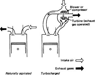
The full potential of this increase in air inlet density by pressure charging is, however, marginally offset by an increase of air temperature due to adiabatic compression in the turboblower. This loss is recoverable by the use of charge air coolers (inter-coolers) placed downstream of the turboblower, which have the effect of increasing the fuel/air ratio, allowing more fuel to be injected into the cylinder and so raising the engine’s power output. The lower air intake temperature has the further effect of reducing not only the maximum cylinder pressure but also the exhaust temperature, and with it the engine’s thermal loading. Increase in engine power over a straight turbocharged model is usually of the order of 20–25% and thermal efficiencies of over 40% are obtainable.
Air-to-air charge cooling is usually carried out in a section of the engine’s radiator. An alternative water-cooled arrangement uses either a separate radiator circuit for charge-air cooling water or, in marine installations, sea-water-cooled heat exchangers with finned tubes carrying the sea-water and over which the charge air passes.
26.5.2 Engine features
In generator drives, the compression-ignition engine is usually a multi-cylinder unit classified by the synchronous speed required, the type of fuel to be used, and the mechanical arrangement (i.e. the geometric arrangement of the cylinders).
26.5.2.2 Synchronous speed
Consistent with the output power required, the operating speed N (revolutions per minute) is determined by the frequency f (hertz) and the number p of generator pole-pairs in accordance with the relation N = 60f/p. Thus a two-pole generator must be driven at 3000 rev/min for 50 Hz or 3600 rev/min for 60 Hz; and for an eight-pole generator 750 or 900 rev/min.
26.5.2.3 Fuels and operating modes
(1) In its compression-ignition form the internal combustion (i.c.) engine may be run on liquid fuels using either distillate or light or heavy residual oils.
(2) As a high compression unit in its compression-ignition form, the i.c. engine may operate in a dual-fuel mode using a mixture of gas and air ignited in the cylinders by the injection of a small pilot charge of liquid distillate fuel. The pilot fuel consumption is between 5 and 10% of the normal full load quantity required for straight diesel operation and it remains fairly constant throughout the load range unless there is a gas shortage, in which case any input energy shortfall is made up by an increase in liquid fuel injected. Should the gas supply at any time fail or become inadequate for the load demanded, the engine automatically reverts to the straight diesel mode. Because of the need to modulate both oil and gas flows, the control and protection system needed is more complex than for straight diesel or gas engines.
The engine may be switched at any load from dual-fuel to diesel operation, and vice versa. The same output rating must therefore be selected for both diesel and gas operation.
(3) As a spark ignition unit the i.c. engine may operate on gaseous fuels such as natural gas, propane or sewage gas.
(4) Finally, in an alternative-fuel form, an i.c. engine may be designed to incorporate both fuel-injection and spar-kignition systems to give operation on either liquid or gaseous fuels. More often than not change to either type of fuel requires engine stoppage, but link mechanisms can be fitted to disconnect the fuel pump drive and close the air intake whilst simultaneously energising the electrical ignition and turning on the gas input. Changeover may then be effected with the engine running, much as in the dual-fuel mode described above. It must be appreciated that output rating will vary with the type of fuel used; it will be lower for gas operation owing to the change in compression ratio.
26.5.2.4 Mechanical arrangements
Perhaps the most widely applied engine format is the vertical design in which the cylinder axes are perpendicular and in-line. In the medium-speed range vee-form engines offering high power in a small bulk are attractive, particularly for trailer-mounted and transportable generator plants. The included angle of the vee may range from about 35° to 90°. Other arrangements occasionally used are horizontal designs, opposed piston engines of various forms and vertical twin crankshaft or double-bank engines.
26.5.3 Engine primary systems
Most modern compression ignition engines have a mechanical or airless fuel injection system embodying jerk-pumps. Medium-speed engines tend to use individual camshaft-actuated pumps for each cylinder. Higher-speed engines employ block pumps within which all the jerk-pump elements are incorporated and driven from a self-contained camshaft which, in turn, is coupled to an auxiliary drive from the engine. Certain two-stroke engines use the common rail system, wherein fuel is maintained at a constant pressure by a pump and a hydraulic accumulator. A fuel valve at each cylinder, driven and timed from the main camshaft, delivers the fuel to the engine.
The injector, the device that introduces the fuel by spray into the combustion space, is in essence a spring-loaded needle valve, whose tip covers the injector nozzle hole(s). The number of holes, their angles and the angles of spray are largely dependent upon the shape of the combustion chamber. Since fuel systems must have small passages and nozzle holes, it is of paramount importance that the fuel within these systems is well filtered.
26.5.3.2 Lubrication
The lubricant in an engine performs many tasks. In addition to reducing friction (and the potentially considerable power loss due to it) and minimising wear, its purpose is to provide:
(1) cooling (either under-crown and/or in piston ring areas);
(2) cleaning and flushing of impurities; and
(3) absorption of shocks and impacts between bearings and other engine parts.
It also affords a seal between piston rings and cylinder walls to reduce the seepage of gas that passes between the piston and cylinder walls from the combustion chamber into the crankcase.
Most engines use a pressurised or force-fed system to circulate the lubricant from an external drain tank or from a sump in the base of the crankcase. The main components of any system are: the circulating pump, which may be either of the gear or the multi-lobed rotor type; a pressure relief valve; oil filter(s) and an oil-to-engine coolant heat exchanger fitted between the feed pump and the filters. Delivery pressure is normally in the range of 50–200 kPa (0.5–2 kg/cm2) but it may even be as much as 400 kPa in high-speed engines.
In the so-called dry-sump system two pumps are employed. Oil that has circulated through the engine oilways returns by gravity to the crankcase pan. The task of the first pump is to transfer this oil from the pan to a reservoir tank external to the engine. The second pump draws oil from this tank and delivers it via the heat exchanger and filters to the bearings, etc.
The arrangement, mainly used on high-speed engines, in which the crankcase oil pan is in itself the reservoir is known as a wet-sump system.
Probably the most severe cylinder wear conditions occur just after an engine has been started, when piston lubrication is at its poorest. For this reason pre-priming systems are incorporated into both the manual start procedures and automatic start controls of low-speed and higher-rated medium-speed engines. It is also advisable to use periodic priming of lubricant on the larger high-speed engines, when these are operating in the automatic stand-by mode. Oil fed from a separate electric-motor-driven pump is circulated at periodic intervals through the oilways to flush the liners and generally wet the engine moving parts in readiness for an automatic start. Periodic priming also has the advantage of reducing the severe wear that can occur on cylinders due to condensed combustion products when an engine is at standstill.
26.5.3.3 Cooling
Engines may be either air cooled, using a mixture of air and oil as cooling medium, or water cooled with water and oil as the cooling media. Air cooling is simpler and is satisfactorily applied to high-speed engines up to approximately 400 kW output. Air is drawn into an impeller (usually secured to the engine flywheel or vee-belt—driven off the crankshaft) and discharged through shrouding across the finned external surfaces of the cylinder and cylinder heads. Whilst very low output engines may not require separate oil-to-air lubricating oil heat exchangers, they are standard features on larger engines.
Good installation of air-cooled engines is critical especially in high ambient conditions and in confined spaces. Care must be taken with the design and application of air intake and hot air outlet trunking to avoid, in particular, the possibility of hot discharged air being recirculated within the generator housing.
Water-cooling by circulation of water through cylinder jackets is the cooling method most frequently applied to engines in generating plants. Detailed arrangements vary considerably but most installations employ some form of closed-circuit jacket cooling system to transfer the engine heat to a heat exchanger. This may be a fan-cooled radiator or a shell-and-tube type heat exchanger. Thermostatic elements are incorporated within the systems to bypass the heat exchanger when starting from cold so as to allow the engine to attain its operating temperature more quickly.
Radiators may either be mounted on the same baseframe as their engine-generator assemblies, or remote mounted. Set-mounted radiators usually have engine-driven cooling fans, whilst remote units incorporate single or multiple fans driven by electric motors. At ratings below 1 MW, single or double sectioned radiators are employed. On larger engines multi-sectioned units are used to provide separate circuits for jacket water, lubricating oil and charge air cooling.
Since most modern medium- and high-speed engines are designed for high-temperature coolant conditions they employ pressurised closed circuit cooling systems. System pressures vary between 30 and 70 kPa (0.3–0.7 kg/cm2) in practice. They equate to system boiling points at sea level of 107°C and 115°C, respectively, so that engine makers may design for corresponding maximum operating temperatures at engine outlet of 80°C and 90°C.
Where a plentiful and cheap raw water supply of good quality is available at less than 30°C, it may be used as a secondary fluid to circulate through an engine’s tubular heat exchangers before it is run to waste. Pre-knowledge of the character and quality of the water is necessary to ensure that correct selection of materials for the tubes and shells of the heat exchangers is made.
Where a raw water supply is of dubious quality, clean (or treated) water may be used in a secondary closed circuit, which is in its turn cooled by the raw water in, for example, a cooling tower. Figure 26.39 illustrates diagrammatically an arrangement for a system of this kind. Whatever the system, it is advisable to use a high rate of jacket circulation with a small temperature difference between engine inlet and outlet, rather than a slow circulation and a large temperature rise.

26.5.3.4 Induction
Every engine should have air-intake filtration/silencing equipment. The induction system must be designed to supply clean dry air to the engine at as near ambient temperature as is possible and with the minimum of restriction. Engine makers stipulate the maximum permissible restriction at induction manifold or turbocharge inlet. The quality and quantity of the air supply has a direct bearing upon the engine output, fuel consumption and life.
Choice of filter depends upon the plant environment and the service life required. The following suggest the duty category in which the various filter types may be applied. The engine maker’s recommendations should be sought and complied with.
(1) For plant installed in sheltered and low dust concentration conditions: oil bath or paper element (dry) type filters, both types without pre-cleaner stages.
(2) For installations in temperate, relatively dry and moderately dusty conditions: oil bath or dry element filters with centrifugal pre-cleaner stages and with greater dust holding capacity than those in (1).
(3) For severe dust concentration applications or where regular maintenance is not always possible: heavy-duty paper element filters with highly efficient (90–95%) centrifugal pre-cleaner stages and preferably with self-emptying or dust unloading arrangements. Filters of this type usually offer safety elements as an optional feature. Their purpose is to protect the engine in the event of main element perforation or act as temporary substitutes when the main elements are being serviced.
It is good practice to fit air restriction indicators to dry type filters to warn when the elements have reached a pre-set limit of fouling.
26.5.4 Engine ancillaries
The two main energy sources for engine starting are batteries for electric-start systems and air receivers for air-start systems. On small high-speed engines hydraulic energy or spring type inertia systems are occasionally employed. The simplest method of starting is of course manual cranking, but it is practicable only with the smallest engines. On the very largest low-speed engines small pony i.c. engines are sometimes employed to give crankshaft rotation at starting through a clutched pinion engaging with the engine flywheel gear ring.
Most electric-starting systems use motors fitted with Bendix-type pinions on their armature shafts to mesh with a toothed rim on the engine flywheel. Lower output engines in the high-speed range may require only one such motor whereas larger engines in that range, and medium-speed engines, need two motors with a common synchronising control.
Starter motors are either of the axial or co-axial type. In the former the complete armature assembly and pinion move forward axially to engage with the flywheel teeth. On the latter type only the pinion dome moves forward to engage under reduced power. This minimises engagement shock and reduces wear on the gear teeth. Starter windings may be of the ‘hold-on’ or ‘non-hold-on’ type. The non-hold variety is usually applied to motors for remotely or automatically started engines. The most frequently used voltages are 12 and 24 V, but 6 V for small engines and 32, 48 or 64 V for the top end of the electrically started range of engines are not unusual.
A cost-effective alternative to starter motors may be applied on generating sets below 15 kW rating, making use of a special d.c. starting winding within the generator to motor the engine. The same winding is used for charging the starter battery when the engine is running.
Starter batteries are either of the heavy-duty lead–acid type or alkaline type. The latter, in its nickel–cadmium form, has been favoured for stand-by generators because it retains its charge better over longer periods without use. Disadvantages are: that it is bulkier than the lead–acid battery of similar capacity; it is more expensive; and it tends to have a larger terminal voltage drop with heavy starting current drain. Maintenance-free, sealed storage batteries, using gas recombination technology, have been increasingly applied on stand-by plants in the last 5 years.
As a typical illustration the capacity of a lead–acid battery required to give six consecutive 20 s cranking periods with 5 s rest periods between each at ambient temperatures down to −7°C on an eight-cylinder vee-form engine rated at 600 kW is 236 A-h at the 5 h rate for a 25% discharged condition. At this temperature the steady cranking current demand at 80 rev/min is of the order of 1 kA corresponding to an engine cranking torque of 1 kN-m. Breakaway current and torque figures are as much as 150% above these values.
Starting difficulties, particularly in low ambient temperatures, are more usual on the smaller high-speed engines because their large surface area-to-cylinder volume ratios tend to dissipate the heat of compression. Moreover, restrictions on the size and weight of starting equipment limit the amount of starting torque available. Various proprietary starting aids are available: devices such as electric glow plugs or those using ether–air mixtures pumped into the air inlet manifolds to give access to the engine combustion chambers to promote combustion. Decompression mechanisms may also be used to hold off either the inlet or the exhaust valve on each cylinder, during the initial starting period. Once the engine is up to steady cranking speed, full compression is restored. The engine should then fire and run up to self-sustaining speed.
Compressed air for engine starting may be expanded either in an air motor engaging with the flywheel or directly within the engine cylinders, to move the pistons downwards on their working strokes until firing occurs. As in the electric starter the drive of the air motor is through a sliding pinion. Air motors may be applied to the range of engines that otherwise uses electric starter motors.
Direct air starting applies to the larger medium-speed engines and to low-speed units. Air is directed to each of the engine cylinders, in their proper firing sequence, through non-return valves either from a camshaft driven distributor or through mechanically operated valves.
Compressed air for either form of starting is stored in one or more receivers at pressures between 100 and 300 kPa (1–3 kg/cm2). Air charge is maintained by a small single-stage auxiliary compressor driven by an electric motor, an i.c. engine or by the main engine itself. On large or critical installations it is usual to provide back-up auxiliaries; the primary compressor being perhaps electric-motor-driven with an i.c. engine-driven stand-by unit.
26.5.4.2 Governors
Diesel generators use variable speed governors set to operate at the predetermined synchronous speed. Choice of governor is dictated by:
(1) The engine type and its application. For example: independent operation feeding an isolated load or parallel operation with similar generators or with a utility supply.
(2) The standard of governing required, i.e. defining the limits for speed regulation (speed droop), steady-state stability and dynamic behaviour. (Classes of governing accuracy and their parameters are defined in BSS 5514: Part 4 and its corresponding International Standard ISO 3046: Part 4.)
(3) The available inertia or flywheel effect of the combined engine and generator. It may be possible to employ a relatively simple mechanical governor in conjunction with a higher inertia flywheel to meet a tight governing specification in an economical manner without recourse to a more sophisticated and expensive governing system. Engine makers will calculate the minimum generating set inertia required for each eligible type of governor to fulfil the requirements of any governing system.
Governors vary from the simple all-speed mechanical type through various forms of mechanical-hydraulic and electro-hydraulic types to all-electric or electronic types.
The mechanical types use rotating flyweights to measure engine speed. The weights move radially and assume a position related to the speed of the engine. In the straight mechanical governor this position is directly translated to the fuel pump rack. Speed setting is usually fixed (or adjustable through only a very narrow speed range) and speed droop is non-adjustable. Pre-selection of speeder springs provides a choice of droop settings—between 4 and 12%. Most high-speed diesel generators up to 1 MW capacity use block type fuel pumps with an all-speed mechanical governor fitted to one end of the injector pump housing. Mechanical–hydraulic governors amplify flyweight movement through a hydraulic servo system to the fuel rack(s). Droop is readily adjustable from 0 to about 8%.
In the electronic governor, engine speed is measured through a magnetic pick-up usually mounted in the flywheel housing to detect the gear teeth on the flywheel rim. The signal so derived is compared with a potentiometer-set speed reference. Any detected difference is amplified within a control unit to adjust the signal to an hydraulic or electrical actuator fitted to the engine fuel rack to correct the fuel and return the engine to its preset speed. Response to speed changes is much faster than with the mechanical—hydraulic types and fully isochronous load sharing is possible on paralleled generators with these types of governor. Moreover, they may be used with a wide selection of control modules to provide fully automated and integrated multi-generator installations.
Where a governor is independently mounted from fuel injector pump(s) it is critical that the engine be fitted with some form of overspeed shutdown device, either acting directly on the fuel pump rack(s) or completely cutting off the intake air flow to the engine. This is necessary to prevent over-fuelling of the engine should any casual jamming of racks and fuel control levers take place or should any of the elements within the governing system fail.
26.5.4.3 Engine monitoring
It is essential that the strategic temperature, pressure, speed and flow parameters of an engine system are regularly monitored to interpret its behaviour and performance and relay this information to planned maintenance operations.
Maker’s instruction books give a good indication of the degree of instrumentation required. Much also depends upon the build specification for the particular engine but parameters such as those listed below may be monitored by instruments, wherever applicable.
(1) Jacket and raw water temperatures, pressures and flows.
(2) Lubricating oil temperature and pressure.
(3) Differential pressures across fuel and lubricating oil filters.
(4) Jacket water temperature at outlets from individual cylinders.
(5) Exhaust temperatures at individual cylinders and before or after turbochargers.
(6) Charge air temperatures and pressures.
(8) Engine, pumps, compressors, and other relevant speeds.
(9) Fuel temperature and pressure.
(10) Fuel and lubricating oil tank levels.
(11) Mechanically driven or transducer operated cylinder pressure indicators.
Abnormal operating conditions may be detected by sensors whose output signals are fed into alarm/shutdown logic controls. Various combinations of indicative and protective action are possible:
The conditions to be covered may include:
(1) high jacket and raw water temperatures;
(2) low lubricating oil pressure;
(3) high exhaust temperature before turbocharger;
(4) high differential pressure across both fuel and lubricating oil filters;
This list is by no means exhaustive and the engine maker’s advice should be sought on the extent of protective insurance to be taken.
26.5.5 A.c. generators
Generator technology is dealt with in Chapter 20. Engine-driven generators for outputs of 20 kVA and above have direct-compound or brushless excitation.
Compounded generators use the load current to provide part of the excitation. They have good overload capacity and rapid voltage recovery, and may be preferred for marine application where large induction motors have to be started.
Brushless excitation is common for diesel-generator plant. The exciter is a three-phase machine connected to a shaft-mounted rectifier diode assembly the output from which is fed to the main generator field. The brushless machine may be self-excited from its output terminals through a solid-state automatic voltage regulator (a.v.r.). The d.c. output from the a.v.r. feeds the stator field of the a.c. exciter to control the output voltage of the main generator. Alternatively, the exciter may obtain its field supply from a shaft-mounted permanent-magnet pilot exciter in combination with an a.v.r.
For medium- and low-speed generators the rotor is usually of laminated form with fully interconnected damper windings. In some high-speed sets the poles have solid bolted-on shoes, which provide eddy-current damping.
26.5.5.1 Construction
Types of construction and mounting arrangements are designated in BS 4999: Part 107 (IEC 34-7).
Almost all diesel-generator sets employ direct coupling of the prime-mover and generator. The latter may be treated either as a separate machine flexibly or solidly coupled to the engine, or flange-mounted to the flywheel housing and close coupled.
Most two-, four- and six-pole machines incorporate end-shield-mounted, grease-lubricated ball and roller bearings. Above about 3 MW, plain bearings are sometimes employed, self- or oil-scavenge lubricated. The large slow running machines tend to use single or dual pedestal outer bearings, mounted on a common baseframe with the generator stator casing.
26.5.5.2 Protection
Where generators are housed in buildings or canopies and enclosures, protection to IP23 of BS 4999: Part 105 is sufficient. (The technically equivalent standard is IEC 34-5.) Ventilation is provided by an internal shaft-mounted fan drawing air from the non-driving end and discharging it at the driving end. Dust filters may be fitted to this type of enclosure when the inlet air contains fine dust, sand, moisture or oil vapour. An output power reduction factor of about 0.95 should be applied to compensate for the resulting restricted cooling air flow. It is advisable to use thermistor temperature-sensing probes, either embedded in the stator windings or placed in the cooling air flow, to guard against damage by overheating, if the filters are not cleaned at regular intervals. For operation in extremely dirty conditions and on outdoor sites such as quarries, a totally enclosed construction, using closed-air-circuit ventilation, should be specified. The closed-circuit air is directly cooled by air-to-air (TECACA) or air-to-water (TECACW) heat exchangers, which may be attached to the generator casing. These enclosures are defined as IP45.
26.5.5.3 Voltage
In the UK the preferred output voltages for three-phase 50 Hz supply, and the appropriate ratings of engine-driven generators, are:
![]()
Voltages of 2.4, 4.2, 6.9, 13.2, 13.8 and 15kV are encountered in American and European practice.
BS 4999 requires the output voltage to be held to within ±5%, but most a.v.r.s will control to ±2 1/2% over the load range. Regulation down to ±1% is possible with solid-state devices in closed-loop control systems.
Standard classification for insulating materials is given in Chapter 7. Most machines up to 3 MVA employ class E or F insulation, or combinations thereof, for stator and rotor windings.
26.5.5.4 Parallel operation
Active power load-sharing is a function of the engine and its governing system. The sharing of reactive power is determined by excitation and synchronous impedance: proper sharing is obtained by applying quadrature current compensation (q.c.c.) to give automatic controlled droop of the output-voltage/reactive-current relation. The amount of droop should be the same for each generator paralleled into a power system: it is typically about 5%.
26.5.5.5 Short-circuit performance
Fast-response brushless and compounded machines can have subtransient short-circuit current levels of 6 to 10 times full-load current. But where excitation is derived from the output voltage, a short-circuit removes the excitation supply and the generator voltage collapses.
In distribution networks it is essential that an adequate ‘permanent’ short-circuit current is maintained by the energy source in order to allow discriminative operation between protective devices such as circuit-breakers, fuses and overcurrent releases. This is necessary if faults on final circuits are to be cleared as quickly as possible. Maintenance of short-circuit current at a level 2 to 3 times full-load current may be achieved by excitation power derived from current transformers in series with the generator output leads. This power is fed to the exciter field through a relay which closes when the output voltage collapses.
26.5.5.6 Generator selection
In selecting the right size of generator for a specific application the following factors, all influencing the rating, should be considered.
(1) Application: the mode of operation, e.g. stand-by or continuous; single running or paralleled with a utility supply or with similar generators; load power factors.
(2) Location: altitude, ambient temperature, humidity and other environmental conditions.
(3) Dynamic loading: any limitations imposed on voltage transient performance in the starting of large induction motors or on waveform characteristics where static converter equipments or thyristor drives form part of the load.
26.5.6 Switchgear and controls
Factors affecting the choice and design of switchgear will be:
(1) The size and nature of initial and future loads. For example, spare panel positions should be considered in an initial switchgear layout, to cater for future extensions.
(2) In-service condition. These relate to such aspects as temperature, humidity, air conditioning and ventilation, dust, corrosion or pollution conditions and affect not only choice of components but also enclosure design.
(3) Foreknowledge of standard equipment available in the market. Custom-built equipment is not justified when standard and competitive units may be readily adapted.
(4) Requirements for reliability and security of supply. For example, the degree of security required influences the choice of bus-bar systems both in terms of numbers installed and their sectionalising.
(5) Requirements for maintenance and safety, consistent with the skills of operating personnel.
26.5.6.2 Fault considerations
Overcurrent protective devices must operate to isolate short-circuit faults safely, minimise damage to circuit elements and avoid, if possible, shutdown of plant. An accurate knowledge of prospective fault currents throughout the system is essential for the correct application of protective devices and the design of bus-bars and terminal arrangements to withstand consequential mechanical and thermal stresses.
Generator short-circuit fault current decreases from a high initial value determined by the subtransient reactance X″d of the machine, through a lower value determined by the transient reactance X′d, settling after 0.6–2.0 s to a steady-state level determined by the synchronous reactance Xd. Circuit-breakers and fuses should operate before the steady-short-circuit condition is reached.
System faults are also fed by synchronous and induction motors, which may generate by release of kinetic energy by their rotating masses. The fault contribution from an induction motor ceases after a few periods. Typical values of subtransient and transient reactance, in per-unit on a machine-rating base, are:
In the calculation of system fault levels it is sufficient to employ reactances only, except that in low-voltage (l.v.) systems the resistance of cables cannot be ignored. Arcing impedances should be included in l.v. system calculations. Typical values of per-unit arcing-fault current on 0.415 kV three-phase systems are: 0.70 for a three-phase arc, 0.57 for line-line and 0.14 for line-neutral.
26.5.6.3 Instrumentation and metering
Single running sets require an ammeter in each line (or an ammeter and a selector switch), a frequency indicator and a wattmeter. Optionally, a watt-hour meter and a power recorder may be fitted.
The instrumentation on each of any parallel running sets should include: an ammeter in each line (or a single ammeter with selector switch) a wattmeter and a reactive volt-ampere (var) meter. Power-factor meters may sometimes be substituted for var meters but as they develop low torque at low load they are prone to reading errors below 25% of rated current. The power factor calculated from kilowatt and kilovar values provides a more reliable and accurate indicator. Additionally, a set of synchronising instruments, perhaps mounted on a swivelling frame, is required, comprising a synchroscope, a double movement voltmeter and a double movement frequency indicator. Any incoming generator before being paralleled to the busbar should be connected by plug or switch to the ‘incomer’ movements of this voltmeter and frequency indicator, the second movements of both instruments being permanently connected to the bus-bars.
Recording instruments provide useful information for reconstruction of events, for registering operational patterns and indicating trends. In their multi-channelled form they give a time-sequenced record of events during disturbances and faults, particularly when they simultaneously monitor closing and tripping of key circuit breakers in the system.
26.5.6.4 Protection
The parameters to be monitored on the prime-mover have been dealt with in the preceding text. Protection related to the generator for which provision should be made, might in addition to system-fitted protective devices safeguarding against external short circuits and overcurrent, include the following:
(1) Restricted-earth-fault protection, combined if necessary with overcurrent protection in the one relay.
(2) Differential (circulating current) protection, where access is possible to the stator windings before the star point. Where a generator and step-up transformer are directly connected, an overall-biased differential protection scheme could be considered.
(3) Stator earth-fault protection. It is possible to combine this with differential protection in the one relay.
(4) Rotor earth-fault protection, by field or stator monitoring.
(5) Generated overvoltage and overfrequency protection.
(6) Unbalanced loading protection, with negative-phase sequence protective gear.
In addition, for generators running in parallel:
(9) Relays should be set to operate at about 10% reverse and be time delayed.
Voltage surge protection should be considered where vacuum breakers or contactors are used, particularly with larger and higher voltage rated generators, if surges induced by lightning discharges on lines external to the diesel generator plant or initiated by switching are likely.
26.5.6.5 Control gear
Control gear should be designed to give a comprehensive indication of the state of a generator plant at all times and provide the means for modifying that state. Equipment for this purpose would include: measuring instruments, condition indicators, alarm annunciators, prime-mover and generator regulating controls and command signalling devices to engines and switchgear.
On the simplest single-generator installations, instrumentation and logic controls are usually incorporated within the switchgear cubicle(s) to give convenient operation of the plant from one location. On the more complex multi-generator plants, since adjustments on one machine affect all others in parallel with it, simultaneous observation of all the effects of any one action is essential. Where only two or three generators are involved, individual switchboards arranged as for the single generator may suffice, provided that they are placed as close together as possible and preferably in a quiet location away from the noise of running machinery.
But where adequate observation of a greater number of switchboards is difficult from one vantage point, it is advisable to use a control desk placed some distance in front of the composite switchboard. This may be used to house the generator regulating and control equipments whilst instrumentation and switchgear indicators are retained on the individual switchboards. Where size and cost of an installation warrants, a mimic diagram, representative of the complete generator plant and its feeder networks, may be incorporated into this control desk. Alternatively, it may be fitted into a separate diagram panel surmounting the composite switchboards. The diagram should incorporate pilot lights and semaphores to represent circuit-breakers, bus couplers, isolators and selector switches with miniature indicating instruments to cover feeders and generator output conditions.
26.5.7 Operational aspects
Since the i.c. engine is an air-aspirating machine its output is affected by changes in the temperature and the pressure of the air it breathes. Power ratings should be quoted to the Standard Reference Conditions (S.R.C.) contained in the applicable National Standards of the engine maker concerned. For British built engines this is BS 5514: Part 1, which is equivalent to ISO 3046/1. Although corresponding German (DIN 6270), American (SAE J-243) and Japanese National Standards cover the same technical subject matter, their treatment of it differs, particularly with regard to the standard reference conditions adopted and definitions of kinds of power.
BS 5514, which covers reciprocating i.c. engines using both liquid and gaseous fuels, applies the following standard reference conditions:
| Total barometric pressure | 100 kPa (750 mmHg) |
| Air temperature | 298 K (25°C) |
| Relative humidity | 30% |
| Charge air coolant temperature | 298 K (25°C) |
The ISO standard power rating of the engine has to be adjusted for ambient conditions falling outside the standard reference condition, to arrive at a predicted on-site or service power rating. Section 10 of BS 5514: Part 1:1987 sets out the method for re-rating RIC engines. It lists the formulae to be applied for this purpose; and Annexes B to G offer tables and examples to help simplify and explain the methods of calculation. Since the calculations are fairly complex (see Annex G of BS 5514: Part 1), most engine manufacturers reduce the formulae to simplified forms stating: the percentage reduction in power for a certain increase in temperature and altitude, above the BS 5514 SRC levels. As it is rare, in any part of the world, for high humidity to be combined with very high temperature, a de-rating exceeding 6% for humidity is seldom, if ever, warranted.
The power categories of importance to the diesel generator user are ‘continuous power’; and ‘overload power’, as defined in BS 5514: a footnote states that it is customary to permit an overload of 110% power ‘for periods and speed corresponding to the engine application’. Engine makers almost universally permit 10% overload for 1 h in any 12 of continuous operation on generator application. In so doing they rightly perpetuate a requirement of BS 649, which was withdrawn on publication of BS 5514 in 1977.
Prospective engine users should be wary of rating classifications other than those above, for generator applications, e.g. stand-by rating, continuous duty with time-limitation rating, reserve rating, intermittent rating and maximum rating, to name but a few of those cited. American, European and Japanese manufacturers will usually declare ISO standard power ratings, when asked.
26.5.7.2 Fuel oils
Liquid fuels used in compression-ignition engines are categorised as either distillate fuels or residual (blended) fuels. These are further subdivided into classes based upon viscosity, measured in seconds, using either the Redwood or the Saybolt systems. A fuel with a viscosity greater than 150 s Redwood No. 1 (expressed as 150 SRI) at 37.8°C is normally considered to be a residual oil.
BS 2869 lists nine classes of fuel oil, two of which, classes A and B, are specifically produced as engine fuels. Of the remaining seven, classes E, F, G and H are classified as industrial and marine fuels: E and F are light residuals or boiler fuels, G and H are heavy residuals or bunker fuels. The distillates, class A (gas oil) and class B (diesel oil), are the most widely used fuels on medium- and high-speed engines. Their American ASTM diesel fuel classification equivalents are D 975-66T Nos 1-D and 2-D. Grade 4-D of ASTM.D 975-66T, although considered a distillate oil, is intolerable to some high-speed engines and is best suited to low- and medium-speed units.
Almost all medium-speed engines will operate on the class E and F light residual fuels, whilst crosshead two-stroke low-speed engines and some of the slower running medium-speed four-stroke engines can successfully operate on class G and, to a lesser extent, class H heavy residual fuels. Residual fuels must be pre-treated, i.e. settled, heated, separated by centrifuge and filtered or waterwashed before being transferred to an engine fuel system. Heavy fuels should not be mixed with gas, distillate or light residual fuels.
The effects that fuel constituents have on engine performance and their influence on maintenance may be briefly summarised as follows:
Viscosity: The lubricating property of the fuel falls as the viscosity reduces. Fuel injection equipment is most affected by any reduction in fuel lubricity or excessive water content in the fuel. Special precuations are necessary when ‘dry’ fuels such as Avtar, Avtag and Avcat are used with high-speed engines.
Sulphur content: Sulphur in a fuel forms a corrosive acid when it combines with exhaust gas condensates. This is wear-inducing and may be minimised by ensuring that high jacket-water temperatures are maintained.
Canradson carbon residue value: This is a measure of the tendency of a fuel to form ‘coke’ when heated. A fuel with high Conradson value reduces combustion efficiency whilst increasing the rate of carbon build-up in the engine. This, if coincident with a high sulphur content, greatly increases wear rate.
26.5.7.3 Lubricating oil
Selection of lubricant depends on whether the engine has separately lubricated bearings and cylinders (low-speed and some medium-speed engines) or whether it has combined lubrication of bearings and cylinders (all high-speed and most medium-speed engines).
Where separate lubrication is used, specially formulated and refined mineral oils containing anti-oxidant additives are specified for bearings. Some engine operators favour detergent additives despite their tendency to thicken relatively rapidly. Cylinder lubrication calls for a heavier oil than that suitable for bearings, but on many engines the same viscosity grade is satisfactorily applied to both.
For combined lubrication, oils need: a viscosity applicable to both cylinders and bearings; high oxidation stability; sufficient detergency and corrosion inhibition properties. A big proportion of medium- and high-speed engines use a straight mineral oil of the type applied to separately lubricated bearings; but others, especially the highly rated high-speed engines, require heavy duty oils with detergent and contaminant dispersive properties, e.g. MIL-L-46152 specification for naturally aspirated engines and MIL-L-2104C for turbocharged units. If there is any possibility of an engine being subjected to prolonged light-load running, such as on many telecommunication transmitter applications, it is advisable to employ a heavy duty oil even though the engine might not normally require it.
Engine makers will always specify the oil to be used consistent with the duty and rating of an application and the fuel which it is intended to use. Mono-grade oils are normally recommended but makers will countenance the use of multi-grade types, provided that the operator obtains the oil supplier’s assurance that the type proposed meets the certified performance level of the equivalent and acceptable mono-grade oil.
26.5.7.4 Maintenance
The diesel engine and the gas turbine are both i.c. heat engines but since the former employs reciprocating motion it is mechanically the more complex machine and demands a greater skill in its maintenance. Also its wear rate is higher. However, repair services for diesel engines are more readily available world-wide than they are for gas turbines.
Plant operating personnel should be fully familiar with all its component parts and be capable of maintaining it in its optimum condition. Operation must be continuously monitored and accurate records kept so that incipient faults are detected and repair effected before major, unscheduled and costly stoppages occur.
The starting point of any preventive maintenance programme must be the manufacturer’s operator and service manuals. They indicate what needs to be checked and how frequently. Planned schedules should at first rigidly adhere to the maker’s recommended frequencies for inspection checks and maintenance tasks. Only after sufficient operational experience has been accumulated should one contemplate any modification to fit the particular installation and its operating conditions, and certainly not before the first general overhaul (stripping to crankshaft bearing level) has been undertaken. This gives the opportunity to assess achievement against the maker’s wear and renewal limit schedules.
Whilst the service intervals recommended by manufacturers are conservative and based on average experience and temperate conditions, periodicity of inspection and service may have to be increased where, for instance, the quality of fuel is in question or where corrosive and very dusty environments pertain, or where less than 50% loading conditions are initially expected. Over the last decade, engine and component manufacturers have achieved impressive improvements in times between overhauls. Typically, major overhauls on well-maintained high-speed engines may now occur at 15 000 h intervals, whilst those on medium-speed engines could be at between 20000 and 30 000 h—the longer interval applying to the slower running engines.
Careful consideration must be given to plant spares stocks. A more comprehensive holding of both non-consumable and consumable items would be necessary at remote sites or in certain developing countries, where there are no local accredited spares stockists. At locations where there is ready access to good stockists, a much-reduced inventory on consumables is justified.
Even with the most vigilant monitoring, problems can arise at any time. Running plants are usually most vulnerable immediately after commissioning and after general overhauls. Table 26.7 based on 4 years of analyses of the excellent Annual Working Cost and Operational Reports published by the Institution of Diesel and Gas Turbine Engineers, shows the major classes of failure (expressed as rounded-off percentages of total unscheduled stoppages) reported by over 100 diesel and gas engined plants, world-wide.
Table 26.7
The major classes of failure at diesel and gas engined plants
| Class of failure | Percentage of total stoppages |
| Fuel injection equipment and fuel supply | 26 |
| Water leakages and cooling | 16 |
| Valve systems and seatings | 13 |
| Bearings | 7 |
| Governor gear | 6 |
| Turbocharger/lubrication/piston assemblies/gearing and drives | 4 each |
26.5.8 Plant layout
The size of a plant room is largely determined by the number and rating of the generators installed and by their requirements for ancillary equipment. In addition to the engine-generator assemblies there will be switchgear, distribution and control gear, engine starting equipment, fuel service tanks, provisions for fuel and lubricating oil storage, engine cooling systems, exhaust silencing equipments, and (on the larger engines) lubrication and fuel systems external to the engine.
The internal layout should be such that the basic requirement is to construct a station building around the machinery. It is prudent to provide for future expansion. Growth may be in the form of a larger generator unit to replace the original or additional units, in multi-generator plant, to cater for increased load demand. A removable end wall offers one way of providing for future plant room expansion.
A minimum space of 2 m should be allowed around each set to facilitate maintenance. On multi-engined stations there should be sufficient headroom for overhead, installation and servicing cranes—one for large lifts of 10–30 tonne capacity and a smaller unit of about 2–3 tonne. Height to the underside of the common crane rail girder should be such that the distance between the bottom of the hook on the larger crane, when fully raised, and the floor level, is about 6 m for the biggest engines installed.
Most generator-set manufacturers provide an advisory service on foundation requirements. Where sets are not supplied with anti-vibration mountings a concrete foundation block, preferably ‘isolated’ from the main building structure to minimise vibration (and therefore noise) transmission, is necessary. A good empirical estimate for foundation mass is that it should be at least 1.5 times the dynamic mass of the associated diesel alternator. On new civil works a basement can be provided at little extra cost to house engine auxiliaries. Similarly, a gallery can be constructed to accommodate fuel service and water make-up tanks. This reduces the need for pipework trenches within the generator hall itself. Access to basement auxiliaries for replacement or maintenance could be by removable open-mesh gratings.
Where ratiators are fitted to generating sets they should have pusher fans and be installed near to and facing an outside wall, with air ductwork and control louvres to regulate the plant room temperatures. Space between the rear wall and the generator end of each set should be sufficient to allow for end-removal of major components, as required.
For ventilation puposes it can be assumed that approximately 8% of a generator nameplate kilowatt rating is radiated as heat from the engine and generator carcasses. The combustion air required by an engine may be taken to be approximately 9.5 m3/h per nameplate kilowatt. Plant-room air exchange required is then the sum of the ventilation air and engine combustion air requirements. Exhaust gases should be piped to atmosphere through insulant-caulked apertures in an outside wall and silencers should be mounted external to the plant room, if at all possible.
Figure 26.40 gives floor area and height requirements, recommended by the Building Services Research and Information Association (BSRIA) in their Technical Note TN4/79, for individual stand-by generators in the range 50-625 kV-A.
Where noise is likely to be a community problem it is necessary to identify all the noise contributors in the plant and obtain octave-band frequency analyses for each so as to calculate the total generated noise level, in worst-case conditions. This must then be related to any noise level limits imposed by communal interests or local legislation in order to determine the noise reduction required. The appropriate noise control treatments should then be selected to restrict the noise transmitted and radiated from the plant room to a value below the promulgated level. Acoustic barriers, partial enclosures, vibration damping materials, vibration isolation, inertial blocks, lined duct work and splitter silencers in ventilation inlets and hot air discharge outlets are but some of the noise control techniques that could be considered. Any treatment applied should not prejudice the operation, maintenance and safety of the plant.
26.5.9 Economic factors
When considering the installation of private generating plant it is important that proposals are not only technically suitable for purpose but are also economically defensible. The actual or predicted costs of purchased power should be compared with the projected costs of privately generated power for clearly defined electrical and heat load cycles, before any management decision is sought.
(1) Capital costs, embracing land; site preparation and access; foundations; buildings; workshops and tools; fuel storage; the power plant and its ancillary equipments; cranes; stores and non-consumable spares and heat recovery equipment (if applicable).
(3) Operating costs; fuel; lubricating oil; service spares; wages of operating and maintenance staff; insurance; depreciation, interest on capital and rates.
Running costs are related to the pattern of operation, the number, rating and type of engines, the fuel type used, the overhaul intervals and the hours of maintenance per year. The following cost indicators will enable reasonable estimates to be made at the first stage of any appraisal, when alternative schemes are being investigated.
26.5.9.1 Fuel costs
The cost of fuel to generate electricity only can be estimated as one-eighth of the cost of purchased electricity expressed in unit currency per kilocalorie (e.g. p/kal, where 1 kW-h = 0.863 kcal). Assume a consumer purchased 150000 kW-h of electricity over a given period at a total price of 1.5 p/kW-h (= 1.74 p/kcal). This would equate to a cost of purchased power of £2610 over the period. The cost of fuel to privately generate 150 000 kW-h would then be £326.
26.5.9.2 Lubricant costs
Lubricating oil consumption may be taken to be 1.5% of the fuel-oil consumption at full load. To this must be added the quantities representative of any oil changes at routine service intervals. This may vary from between 250 h to every 5000 h of running, depending upon the size and speed of the engine. The sump capacity of a 1.2 MW engine is of the order of 8001. For first estimates of lubricating oil costs, one may work on the basis of 5% of fuel costs for the same period.
26.5.9.3 Maintenance costs
Estimate on the basis of 5% of the combined costs of fuel and lubricating oil over the given period. This covers spares and labour.
26.5.9.4 Depreciation, interest, insurance and rates
Engineers do not always appreciate how substantial these costs can be. A recent economic appraisal for a private generating scheme, employing two 1.2 MW sets (with a third in reserve) operating at a 92% load factor and written down over a 7-year period, revealed that the annual sum of these costs was 70% of the combined total of the other running costs, i.e. those attributable to fuel, lubricant, maintenance, spares and labour.
26.5.9.5 Capital costs
Table 26.8 offers a very rough guide for first estimates on capital costs (including installation), using the cost of the engine generator and its auxiliaries as base 100.
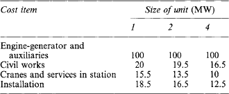
26.5.10 Cogeneration/CHP (see also Section 26.3.4)
A total energy system implies on-site power generation in which the energy input from either liquid fuel (diesel engines) or a combination of gaseous and liquid fuels (dual-fuel engines) is maximised by recovering the waste heat from the generating process. By so doing the overall thermal efficiency of generation may be raised from 37% to about 80%.
Compared with gas turbines the quality of waste heat is of a relatively low grade. Nevertheless, sizeable combined heat and power installations have been commissioned both in the UK and in Europe in recent years, most favouring multi-engined systems employing 1.5–2 MW unit sizes with dual-fuel operation.
Table 26.9 shows typical heat balances for a 2 MW 750 rev/min diesel-generator giving 1.8 MW in the dual-fuel mode.
Table 26.9
Heat balances for a 2 MW 750 rev/min diesel generator
| Heat balance at full load | Diesel (%) | Dual fuel (%) |
| To electricity | 38.5 | 39 |
| To exhaust | 36 | 34 |
| To jacket water | 11 | 10 |
| To lubricating oil | 4.5 | 4 |
| To charge air | 4 | 2.5 |
| To radiation, etc. | 6 | 6 |
| To unmixed gases | — | 4.5 |
| Total | 100 | 100 |
Engines of this type and size give about 1 MW of recoverable heat from jacket water and lubricating oil in the form of low pressure water at 80 °C and another 1 MW recovered from the exhaust gases to give about 1400 kg/h of steam at 850 kPa.
Recoverable heat from a diesel engine is of the order of 250000 kcal/h/MW from the exhaust gases and 350000 kcal/h/MW from the jacket water.
Using exhaust heat recovery alone, 0.5 kg of steam at 850 kPa/kW-h is possible. With full jacket, oil and exhaust heat recovery this figure doubles to 1 kg of steam per kilowatt-hour and can be raised still further to 2.5 kg/kW-h if pre-heating of the jacket water into an automatic boiler, using the same fuel as the engine, is employed.
Whilst it was once considered uneconomical to employ heat-recovery systems on generators below 500 kW, the Electricity Act of 1989 has stimulated interest in small-scale combined heat and power (CHP). A UK potential of 3.5 GW of small-scale co-generation has been estimated, for the next 10 years. The majority of these plants will use engines operating on gaseous fuels; and applications will include:
Recommendations for the electrical, mechanical and thermal protection of plants of this type are contained in publications such as:
(1) The Electricity Council Engineering Recommendations G59;
(2) The Electricity Council’s publication ET 113—Notes on guidance for the protection of private generating sets up to 5 MW for operation in parallel with Electricity Boards’ distribution networks;
(3) British Gas publication IM 17—Code of Practice for natural gas fuelled spark ignition and dual-fuel engines; and
(4) H.M. Department of Energy, Energy Efficiency Office’s Good Practice Guide No. 1—Guidance notes for the implementation of small-scale packaged combined heat and power.
Armstead, H.C.H. The undervaluation of hydro-power potential-a statistical pitfall. J. Mech. Eng.. (March):1985.
Bernstein, L.B. Tidal Energy for Electric Power Plants. Israel Program for Scientific Translation; 1965.
August Bovet, G.A. Modern trends in hydraulic turbine design in Europe. Trans. ASME. 75(6), 1953.
October Braikevitch, M. Fluid engineering & development of water power. In Fourth Fluid Science Lecture. Jerusalem: British Hydromechanics Association (BHRA); 1972.
Braikevitch, M., Hartland, D., Strub, R.A. Development of reversible pump turbines and pump storage equipment. J. ASCF. (October):1961.
Buchi, G. La Moderne Turbine Idrauhche e d’Regulaton di Velocity. U Hoeph; 1957.
Creager, P., Justin, J.D. Hydro-electric Handbook. Milan: Wiley; 1950.
Danel, P. ‘The hydraulic turbine in evolution’. In James Clayton Lecture. New York: Institute of Mechanical Engineers; 1958.
, Hand Book of Applied Hydraulics. Davis C.V.. McGraw Hill, 1942.
Deriaz, P.E., Warnock, J.G. ‘Reversible pump turbines for Sir Adam Beck-Niagara Pumping-Generating Station’. Trans. ASME, J. Bas. Eng.. (December):1959.
April Frau, O.P., Leroze, P.V. ‘Pumping in a tidal power plant-experience at La Rance and main aspects of the turbine design’. In Pumped Storage Proc of I. C. E. Conference. New York: T Telford; 1990.
Gibrat, R., L’Energie des Marees. Presses Universitanes de France, 1953.
GoldWag, E. ‘On the influence of water turbine characteristic on stability & response’. ASME J. Bas. Eng.. (December):1971.
Goldwag, E., Potts, R. Energy Production Developments in Tidal Energy. Paris: I.C.E./T. Telford; 1990.
, Hydroelectric Engineering Practice. Guthrie-Brown, J., eds., 2nd edn. London: Blackie & Son, 1970.
Hammon, N.W., Wood, P. Tidal Power from the Mersey, History & Prospects, Developments in Tidal Energy. London: ICE/T Telford; 1990.
Haws, E.T., Wilson, E.A., Gibson, H.R. Pumped Storage in the Proposed Mersey Tidal Project, Pumped Storage. London: I.C.E./T. Telford; 1990.
May Hilaret, P., Weisrock, G. ‘Optimising production from the Rance tidal scheme’. In Symposium on Wave Tidal OTEC & Small Scale Hydro Energy. London: British Hydromechanics Association (BHRA); 1986.
Hovey, L.M. ‘Optimum adjustment of governors in hydro generating stations’. Eng J.. (November):1960.
Jaeger, C. ‘Present trends in surge tank design’. Proc. Inst. Mech. Eng.. 168, 1960.
Jaeger, C. Engineering Fluid Dynamics. Blackie & Son; 1956.
Kerr, D., Severn, B.E., Driver, S.J. Severn Barrage Civil Engineering Aspects Developments in Tidal Energy. London: I.C.E./T. Telford; 1990.
Kovalev, N.N. Hydroturbines Design and Construction. Israel Program for Scientific Translations. London: Jerusalem, 1963. 1966. ‘La Rance tidal power scheme’. fr. (September/October):1983.
Vol 2 (1960) Masonyi, E. Water Power Development, 2nd edition. Hungarian Academy of Science; 1963.
Meier, W., Muller, J., Grein, H., Jaquet, M. ‘Pump-turbines and storage pumps’. Escher Wyss News. 44(2), 1971.
Mermel, T.W. ‘The world’s major dams and hydro plant’. Water Power & Dam Construction. (May):1990.
Miller, H., Focas, D. ‘The Annapolis tidal power plant’. Proc. I. E. E.. (March):1984.
Nachleba, M. Hydraulic Turbines, their Design and Equipment. Budapest: Artia; 1957.
Petty, D.J., Mcdonald, A. Turbine Generators for the Severn Barrage, Developments in Tidal Energy. Prague: I.C.E./T. Telford; 1990. ‘Power from water, a special report’. Power, 1980;124;4.
Seoni, R.M., Shaded, E.N., Simpson, R.J., Warnock, J.G. ‘Review of trends of large hydroelectric generating equipment’. Proc. I. E. E.. 123(October), 1976.
Tamatsukuri, T. ‘Trends in hydroelectric generating equipment technology’. Hitachi Rev., 1988;37;2. The Severn Barrage Project General Report (Energy Paper No 57). London: HMSO; 1989.
‘The world’s largest turbines’. Water Power & Dam Construction Handbook. London: Reed Business Publishing Group, Sutton, 1991. April. ‘The world’s pumped storage plants-survey’. In Water Power & Dam Construction. Reed Business publishing Group, Sutton; 1990.
Wislicenus, G.F. Fluid Mechanics of Turbo-machinery. McGraw Hill; 1947.
Vivier, L. Turbines Hydrahques et leur Regulation. New York: Albin Michel; 1966.
Zienkievicz, O.C. ‘Transmission of water hammer pressures through surge tanks’. Proc. Inst. Mech. Eng.. 168, 1954.