
Road Transport
JS Davenport, Lucas Automotive Ltd (Section 44.1)
MG Howard, BSc, CEng, MRAeS, MACM (USA), Kennedy and Donkin Transportation Ltd (Section 44.2)
RH Busby, ERD, MSc, CEng, EICE, MIHT, MConsE, Kennedy and Donkin Transportation Ltd (Section 44.2)
SB Preston, Silent Power Ltd (Section 44.3)
MJH Chandler, CEng, FIEE, FICE, FIHT, GEC Traffic Automation Ltd (Section 44.4)
44.1 Electrical equipment of road transport vehicles
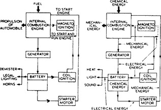
Within the framework of the modern automobile there is an elaborate mechanism to enable energy to be changed readily from one form to another. Although the electrical equipment is only a small proportion of the whole, its satisfactory operation is essential for the normal running of the automobile.
The chemical energy in the fuel is changed within the engine to provide primarily the propulsion of the automobile. A small portion of the transformed energy is taken to operate the electrical equipment. In its turn the electrical apparatus may have to convert this energy into heat (demister), light (legal requirements) and sound (horn), or back to mechanical energy (starter motor).
In addition, the electrical equipment may be called upon to supply energy when the automobile engine is at rest; so an energy storage system is necessary. To store this energy an accumulator or storage battery is used. Electrical energy is converted into chemical energy and is stored in this form in the battery. Figure 44.1 shows the various energy conversions concerned.
44.1.1 Batteries
The type of battery used in automobile work has been designed to withstand severe vibration and give maximum capacity for minimum weight. A large discharge current for a short duration is required by the starter motor and the battery must be able to meet this requirement.
The two main types of batteries used in automobile work are the lead-acid and the nickel—alkaline.
The former has been more extensively used for private cars. The type developed has a large number of thin plates of suitable mechanical strength giving a large surface area for a given weight and volume. This construction enables the heavy current demands of the starter motor to be met. The magnitude of the discharge current is a function of the plate area exposed to the electrolyte. The specific gravity of the sulphuric acid used in these batteries is higher than that for stationary batteries: it lies between 1.150 and 1.300. Between these density limits the electrolyte has minimum resistivity—a desirable condition in view of the occasional heavy discharge rates. Too high a density may cause damage to the plates and separators. If the discharged battery is in a healthy condition, it is permissible, in urgent cases, to recharge in less than an hour to about 75% of its fully charged state by giving a boosting charge or a fast rate of charge, provided the battery temperature is not allowed to exceed 80°C. Typical voltage/time relations for a lead-acid cell are shown in Figure 44.2.

The nickel—alkaline battery is of much more robust construction than the lead—acid battery. The plates do not buckle when short circuited. The electrolyte is a solution of caustic potash, and unlike the lead—acid battery, no indication of the state of charge is given by the specific gravity. The normal working value is 1.200. After about 2 years service the gravity will fall to 1.160, owing to absorption of impurities from the atmosphere. The action of the battery will become sluggish, and complete renewal of the electrolyte is required.
44.1.2 Charging systems
A generator driven by the automobile engine supplies the energy to charge the battery. If a commutator-type generator is used, an automatic switching device (the cut-out relay) is embodied in the circuit to connect the generator and battery when the generator voltage is of the correct value for charging purposes, and to disconnect the generator when the speed of the automobile engine drops below a certain figure or when the engine is at rest. No cut-out is required in an alternator charging system, since the semiconductor diodes built into the alternator for converting a.c. to d.c. output prevent current reversal.
The automobile driving the generator has a wide speed range, so that the electromotive force produced by the generator, which is proportional to the product of the flux and the speed, would vary considerably unless otherwise prevented. If the required charging current was obtained at low speeds, then the battery would receive a charging current in excess of requirements at the normal driving speeds on the open road.
To keep the generator voltage within the limits set by the battery, a reduction in field current is required for increasing speed. The following systems of control have been adopted for d.c. generators: (1) compensated voltage control; and (2) current voltage control.
44.1.2.1 Compensated voltage control
The compensated voltage control system has a single vibrating-contact regulator which carries both a shunt and a series winding. The shunt winding is connected across the generator output and controls a pair of contacts which, in the normally closed position, short out a high-value resistor in the generator field circuit. Ignoring for the moment the compensating action of the regulator series winding, the shunt winding enables a constant voltage to be obtained from the generator. At low speeds the contacts are held together by a spring and generated voltage is applied to the field windings. As speed and voltage rise, the pull of the shunt wound electromagnet overcomes that of the spring and the resistor is inserted into the field circuit, causing the voltage to drop (Figure 44.3(a)), beginning the next contact opening and closing cycle. This vibratory movement of the contacts takes place some 50 times per second and results in a practically constant voltage, the contacts remaining closed for a shorter period of time as speed rises. For applications where the insertion of resistance does not cover requirements over the whole range of speed, a second pair of contacts, which short circuit the field winding, are arranged to close at the higher speeds, which enables constant voltage to be maintained in two stages. Figure 44.3(b) shows a barrel-type double-contact voltage regulator.
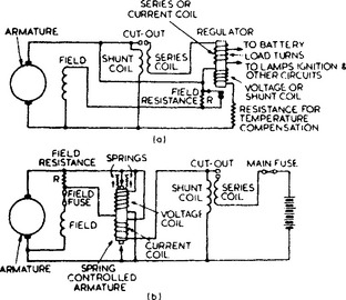
Figure 44.3 (a) Voltage regulator with single contact: minimum field current with R in series with the field winding; maximum field current with no resistance in field circuit; (b) Voltage regulator with double contact: minimum field current when the field winding is short circuited; intermediate field current when R is in series with the field winding; maximum field current when there is no resistance in the field circuit
Constant voltage regulation has to be modified in practice to ensure that current demand by battery charging and other loads is not so high as to overload the generator. In the compensated voltage control system, current control is effected by adding a series winding to the regulator to assist the shunt winding. The voltage characteristic of such a regulator will be a falling one—the voltage will drop with increase of load and thus prevent overloading of the generator. Variation of voltage setting with rising temperature of the voltage coil is prevented by having an armature spring of bimetallic strip type. This temperature compensating device is arranged to give a somewhat higher voltage when cold, to assist in replacing the energy taken from the battery by the starter motor.
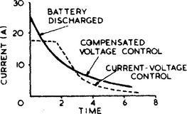
The tapering charge characteristic obtained (Figure 44.4) means that the compensated voltage control system is unable to utilise those occasions when spare generator capacity is available for increasing the charging rate. This drawback is overcome by current voltage control.
44.1.2.2 Current—voltage control
A regulator of the current-voltage type (Figure 44.5) allows the generator to give its safe maximum output into a discharged battery and to continue to do so until the battery approaches the fully charged condition, when the charging current is reduced to a trickle charge. A constant charging current is maintained until a certain battery voltage is reached; then the voltage regulator operates to give constant voltage control. The charging current will decrease until finally a trickle charge is passing through the battery. This type of regulator is used when the vehicle has a heavy electrical load and a more definite regulation is required than that given by the compensated voltage regulator.
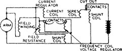
In this type of control two separate regulators are used. These are mechanically separate but electrically interlocked. One regulator is shunt wound and so responsive to voltage conditions; the other is series wound and responsive only to current. Their contacts are connected in series with the generator field circuit.
When current from the generator flows to the battery, it passes through the current regulator winding, and on reaching the maximum rated value, it operates the armature of the current regulator, thus inserting resistance into the field circuit of the generator and decreasing the output current. The vibrations of the armature of the current regulator will prevent the rated output current being exceeded. As the battery voltage rises, the voltage regulator takes over, causing the second pair of contacts to operate, thus controlling the output according to the load and the state of the battery.
If, however, the battery is fully charged with little or no load switched on, then as the speed of the dynamo rises, the terminal voltage will increase to the operating value for the voltage regulator, the resistance will be inserted into the generator field circuit by the operation of the voltage regulator armature and the output current will be a function of the potential difference between generator and battery.
44.1.2.3 Cut-out or reverse-current relay
The cut-out relay is a simple automatic relay and is used to connect the battery to the generator when the latter’s voltage is just in excess of the battery’s. It also disconnects the battery from the generator when a discharge current flows from the battery and the generator tends to run as a ‘motor’.
Two coils are provided on the relay: the first, a voltage or shunt coil connected across the generator terminals; and the second, a series coil carrying the generator output current. The fine-gauge wire coil has a large number of turns, but the current is small. This produces the required magnetic effect. When the current flowing in the voltage coil reaches a predetermined value proportional to the generator voltage, the armature is pulled down and the contacts close, allowing current to flow to the battery. This current flows through the series coil and the combined magnetic effect produced by the two coils pulls the contacts close together. The current coil assists the shunt coil as long as a changing current flows. When the generator speed and voltage fall, the current in the series coil decreases, then reverses, so that the resulting magnetic flux produced by the two coils together decreases. With a further fall in generator voltage the magnetic pull exerted on the armature will be overcome by the pull of the spring and the contacts will open, allowing no further discharge current to flow to the generator.
44.1.3 A.c. generator
The continuing increase in the use of electrically operated components on automobiles calls for higher generator outputs. Higher outputs are also required for vehicles which have long periods of idling or frequent stopping and starting.
The increased currents to meet these needs give rise to commutation difficulties if the size, weight and speed of the dynamo are to be consistent with a reasonable service life. An alternative to increasing the size of the d.c. generator is to produce an a.c. in the generating machine and convert to direct current by means of rectifiers. The a.c. machine can have a higher maximum operating speed, so a higher drive ratio can be chosen which will allow a greater output at lower road speeds.
The alternator has a stationary three-phase output winding wound in slots in the stator so that the generated current can be taken directly from the terminals of the stator winding. There is, therefore, no problem of collecting the heavy current from a commutator. The rotating portion of the alternator carries the field winding, which is connected to two slip-rings with associated brush-gear mounted on the end bracket. The field current is small and can be introduced into the windings without arcing at the brushes. The alternator is not affected by the polarity of the magnetic field or the direction of rotation of the rotor, as in the case of the d.c. machine.
A field pole system of the imbricated type is preferred to salient poles by most alternator manufacturers, as it enables a relatively large number of poles (typically 8–12) to be energised by a single field winding.
The alternator cutting-in speed is about the same as that of the d.c. generator; consequently, it provides a useful charge at engine idling speed. The advantage for the alternator is derived from the higher drive ratio.
Rectifier: Rectification of the alternating current output is by means of six silicon diodes in a full-wave three-phase bridge connection. The diodes are usually built into the bracket at the slip-ring end of the machine.
Control: Since the alternator is designed to be inherently self-regulating as to maximum current output and since the rectifiers eliminate the need for a cut-out relay, the only form of output control necessary is a voltage regulator in the field circuit.
The conventional type of electromagnetic vibrating-contact voltage regulator, with either single or double contacts, has been used. Also employed to enable higher field current to be used and to give longer contact life has been a vibrating-contact regulator with the contacts connected in the base circuit of a transistor, the transistor being protected by a field discharge diode against inductive voltage surges.
To eliminate all maintenance and wear problems, it is now general practice to use solid state components in all parts of the voltage control unit.
44.1.3.1 Separately excited alternator systems
Fitted to a number of passenger cars and light commercial vehicles are Lucas 10AC and 11 AC alternators, which have field systems energised from the battery as opposed to directly from the machines. The fully transistorised control employed for these alternators is shown in Figure 44.6. Used in place of the voltage coil and tension spring of a vibrating-contact regulator are two silicon transistors for field switching and a Zener diode (voltage control diode) for voltage reference. The Zener diode is a device that opposes the passage of current until a certain voltage is reached, known as the breakdown voltage. When the ignition is switched on, the base current required to render the power transistor T2 conducting is provided through resistor R1; as a consequence, current flows in the collector—emitter portion of T2, which acts as a closed switch in the field circuit and applies battery voltage to the field winding. Rising voltage generated across the stator output winding is applied to the potential divider (R3, R2 and R4) and, according to the position of the tapping point on R2, a proportion of this potential is applied to the Zener diode ZD. When the breakdown point of the Zener diode is reached, the diode conducts and current flows in the base circuit of a driver transistor T1. The base current of T2 is reduced and so is the alternator field excitation. To limit power dissipation, it is desirable to switch the voltage across the field winding rapidly on and off instead of using the transistors to provide continuous regulation; this oscillation is achieved by the positive feedback circuit comprising resistor R5 and capacitor C2. Transistor T2 is protected from very high inductive voltage surges by the surge quench diode D connected across the field winding, which also serves to provide a measure of field current smoothing. Radio interference is eliminated by negative feedback provided by capacitor C1. Resistor R6 provides a path for any small leakage currents through the Zener diode that would otherwise flow through the T1 base circuit at high temperatures and adversely affect regulator action. Automatic compensation for changes in ambient temperature is provided by the thermistor connected in parallel with resistor R3.
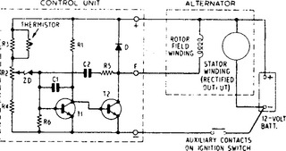
Figure 44.6 Fully transistorised control for a Lucas 10AC or 11 AC alternator (positive earth circuit)
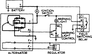
Figure 44.7 shows a typical Lucas 10AC or 11AC alternator charging system diagram, including a field switching relay and warning light control unit of ‘hot wire’ type. The hot-wire resistor is connected to the centre point of one of the pairs of diodes in the alternator; when hot, it lengthens and allows the contacts to open under spring tension, extinguishing the warning lamp.
44.1.3.2 Self-excited alternator systems
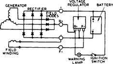
The majority of present-day alternators employ what is known as the nine-diode system, and are self-excited at normal operating speeds. The nine-diode arrangement has become popular owing to the simplicity of the warning lamp circuit, which, if combined with an in-built electronic regulator, provides a machine with the minimum of external wiring (Figure 44.8). The three field excitation diodes for supplying the field with rectified a.c. are included in the rectifier pack. Operating voltage is built up at starting by energisation of the field winding from the battery through an ignition (or start) switch, a non-charge warning lamp and the voltage regulator.
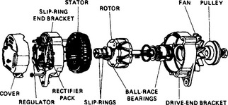
Lucas manufacture a series of alternators of this type—all with built-in electronic control units—having outputs ranging from 28 to 75 A. An exploded view of a typical alternator is shown in Figure 44.9.
Control: In the simple self-excited system shown in Figure 44.8 the regulator controls the voltage at the field diodes’ output terminal and, therefore, controls battery voltage only indirectly. For systems employing high-output alternators or having significant cable resistance between battery and alternator—for example, because the battery is remotely sited—indirect control of battery voltage becomes unacceptable. For such applications, progressive levels of control can be provided as follows: (1) the regulator can be designed to sense and control the voltage at the alternator output terminal; or (2) the sensing lead of the regulator can be brought out of the machine to sense and control battery voltage directly. Method (2) is the most appropriate for remote-battery/high-power systems.
Figure 44.10 shows a Lucas regulator designed to sense alternator output terminal voltage. Field drive transistor T2 is an integrated Darlington-pair device giving increased gain. This enables the circuit resistor values to be substantially increased, thereby reducing the permanent battery drain (taken through the sensing lead) to an acceptable level. Base drive resistor R4 is fed from the sensing lead so that, in the event of the latter being disconnected or broken, T2 is turned off, shutting down the alternator. If R4 were fed from the field diodes, an open-circuit sensing lead would result in continuous maximum output from the alternator and destruction of the battery.
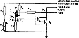
Figure 44.11 is an example of a regulator designed for remote voltage sensing. It includes the safety feature which affords protection against an open-circuit sensing lead (described above) and, in addition, protection against damage from disconnection of the alternator output lead. In the latter event, since the battery is no longer being charged, the battery/sensing lead voltage falls and the regulator therefore increases the alternator field excitation. This increases the alternator output voltage, which further increases field excitation. Without protection this cumulative effect can result in the destruction of the field drive transistor T2. Protection is provided by way of resistor R6 and diode D2. R6 is chosen so that under normal regulating conditions insufficient current flows through the potentiometer chain to reverse-bias diode D2, which is therefore conducting: hence, the regulator controls the sensing lead voltage. The rise in alternator output terminal voltage, which occurs with a break in the output lead, increases the current through R6, causing D2 to become reverse-biased. Regulation of the output terminal voltage now takes place at a safe level dictated by R6, R1, R2, R3 and ZD1, and T1base—emitter voltage. This secondary regulation level is typically 4 V above the normal regulating voltage.
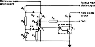
This regulator can be designed to work with a remote network providing battery temperature compensation. The network, which includes a thermistor, is connected in series with the voltage sensing lead and is mounted to sense battery temperature directly.
Lucas alternators incorporating nine-diode systems are also protected against surge voltages arising from disconnection of the alternator at high output currents, and from switching transients resulting from other equipment (e.g. the ignition system). The protection takes the form of a high-power Zener diode connected between the field diodes’ output terminal and earth. Surge voltages are thereby limited to a safe level of typically 35 V. If the Zener diode is overloaded, its normal failure mode is short-circuit. This cuts off the field excitation and switches on the warning lamp. No other damage occurs and the normal charging function of the alternator is restored on the Zener diode’s being renewed. A detailed discussion of transient causes and protection is given in SAE paper number 730043, ‘Transient overvoltages in alternator systems’. Later alternators incorporate regulators whose semiconductor devices can withstand overvoltage surges. On these alternators the separate overload diode is deleted.
44.1.4 Ignition systems
The ignition of the compressed charge in a cylinder of an internal combustion engine with petrol as the fuel is brought about by an electric discharge. This discharge takes place across the points of a sparking plug. The voltage required to produce this spark will vary between 7000 and 25000 V. The equipment may be self-generating, as in the magneto (seldom used on automobiles), or battery powered, as with coil ignition. The high-voltage impulses must be delivered to each cylinder as required and at a precisely controlled time in accordance with engine speed and load. There are several systems now in use to satisfy these requirements.
44.1.4.1 Contact breaker ignition
The major components of a modern coil ignition system are shown in Figure 44.12.
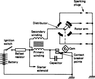
Primary winding: A coil of a few hundred turns of relatively heavy wire connected to the battery through a contact-breaker.
Secondary winding: A coil of many thousand turns of fine wire in which the high-tension voltage is induced. One end is usually connected to the more positive end of the primary winding, the other to the sparking plugs through the distributor.
Contact-breaker: A switch for opening and closing the primary circuit at the required instants. It is operated by a cam driven at half engine speed.
Rotor arm: Together with the distributor head, it forms a rotary switch to distribute the high voltage to each of the cylinders in correct order of firing. The rotor arm may incorporate a resistor to aid radio interference suppression.
Ballast resistor: A device to aid starting. It is a resistor of 1–2 Ω connected in series with the primary winding and arranged to be short-circuited when the starter motor is operated.
Sparking plug: The high voltage is led to the insulated central electrode of the plug (one per cylinder) and the spark passes across the gap at the required instant. The gap must be maintained within certain limits, usually 0.3–1.0 mm. In selecting a sparking plug for a given engine, attention must be given to the engine manufacturer’s recommendations. The reach of the plug must be such that the correct amount of projection into the combustion chamber is achieved. The correct heat grade is also important: otherwise pre-ignition (overheating) or misfiring (too cold) may occur.
Distributor: ‘Distributor’ is a generic term used to describe the assembly of contact-breaker, a capacitor, rotor arm and distributor head. It contains a shaft driven at half engine speed on which is mounted a centrifugally operated mechanism coupled to the cam. The mechanism is restrained by two springs and is so designed as to maintain the relationships between spark timing and speed. The cam has as many lobes as there are cylinders.
Usually incorporated is a vacuum control which automatically advances the ignition timing as the engine load falls. Control is achieved by a spring loaded diaphragm which moves in response to changes in depression in the carburettor venturi. As the depression increases, the diaphragm moves the contact-breaker mounting plate contrary to cam rotation and so advances the ignition. Occasionally, more complex vacuum control devices are employed having facilities to retard the ignition timing under certain engine operating modes (usually closed throttle deceleration) to reduce hydrocarbon exhaust emissions.
44.1.4.2 Electronic (contactless) ignition
In contact-breaker ignition systems, it is necessary for consistent performance to adjust and, if necessary, to replace the contact points at regular intervals. Failure to do so may result in misfiring and/or excessive levels of exhaust emissions, which in most countries are now controlled by legislation. As a result, electronic (contactless) ignition is used on many vehicles—especially in countries with severe exhaust emission regulations. A general circuit is shown in Figure 44.13. The current interrupting function of the contact breaker is now performed by a power transistor, whereas the timing requirement is handled by a sensor in conjunction with a control module.
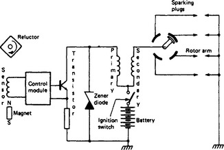
Many forms of timing transducers are in use. That in Figure 44.13 is of variable reluctance type. A permanent magnet drives a flux through a magnetic circuit which includes a pickup coil and the distributor shaft. As the shaft revolves at half engine speed, the flux is modulated by a reluctor (replacing the cam of conventional ignition), which is shaped like a cog with as many teeth as there are cylinders. The varying flux generates in the pickup coil a voltage waveform which, after modification by the control module, switches off the power transistor (and, therefore, the coil primary current), to produce a spark. Timing and distribution of the spark are identical with a conventional contact breaker system.
Other forms of timing transducers are:
(1) a photoelectric sensor which is switched by an infra-red light beam interrupted by a shutter;
(2) a Hall-effect device in which a magnetic field is interrupted by a steel shutter—the varying flux in the Hall device causes a proportional voltage change across it; and
(3) radiofrequency differential transformers and eddy-current transducers in which the output voltage is varied by rotating magnetic devices.
In its simplest form the electronic control module may be an amplification circuit to drive the switching transistor, and the duty ratio of the sensor signal—equivalent to dwell angle in conventional systems—remains unchanged. More complex systems are in use in which the control module calculates the point of current switch-on in the primary winding according to engine speed. This allows use of special ignition coils having a very short time constant. The module also has a current-limiting facility of usually 5–7 A and a device which switches off the current when the engine is stalled. The advantage of such systems is that the ignition spark energy is constant over wide speed and battery voltage ranges. Hence, they are usually referred to as ‘constant-energy systems’.
44.1.4.3 Electronically timed ignition systems
Contactless ignition systems overcome the problems of contact point degradation but the limitations of spark timing by centrifugal and vacuum operated mechanisms remain. As legislation on exhaust emission levels and energy conservation increases in severity, there is an urgent need to improve the efficiency of internal combustion engines, and a greater accuracy and flexibility in spark timing is required. This is possible with computer control of spark timing. A typical arrangement is shown in Figure 44.14.
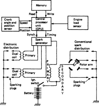
The timing information for the engine is contained in a semiconductor memory unit. Typically the timing values for over 500 points of the engine speed/load characteristic may be stored permanently in the memory. Sensors placed at the engine crankshaft and in the inlet manifold generate signals in accordance with engine speed, crankshaft position and engine load. These signals are processed by the central processor unit (microprocessor) into a binary form suitable for addressing the memory. The nearest timing value in the memory for the particular speed and load of the engine is read into the spark generator unit, where, by means of a count-down procedure, the current in an ignition coil primary winding is interrupted at precisely the instant to produce a spark in the correct cylinder.
The spark generator unit may include a constant energy circuit as previously described, although other more complex energy control circuits may be employed and can be programmed by instructions also held in the memory.
Distribution of the high voltage to the sparking plugs may be achieved by a distributor head and rotor arm, or obtained electronically by sequential switching of the primary windings of dual output ignition coils (two for a four-cylinder engine).
The crankshaft sensors are usually of the eddy current type but occasionally variable reluctance devices are used. Because of their exposed position, a robust construction is essential. A segmented disc fastened either to the rear face of the flywheel or at the crankshaft pulley is used to generate the signals. Where electronic distribution is used, two crankshaft sensors are necessary, the second being required to generate a suitable synchronising signal.
Load signals may be derived from a simple diaphragm operated potentiometer or by a more sophisticated silicon strain-gauge device. Usually the inlet manifold depression is measured rather than that in the carburettor venturi.
More ambitious systems may include programmed timing offsets for ambient temperature, engine coolant temperature, atmospheric pressure and exhaust-gas circulation.
44.1.5 Starter motor
A starter motor is required to run the internal combustion engine up to a speed sufficient to produce satisfactory carburation.
The starter motor is mounted on the engine casing and a pinion on the end of the starter motor shaft engages with the flywheel teeth. The gear ratio between pinion and flywheel is about 10:1. A machine capable of developing its maximum torque at zero speed is required. The series wound motor has speed and torque characteristics ideal for this purpose.
The engagement of the pinion with the flywheel is effected in different ways. Perhaps the two most commonly used are the inertia engaged pinion and the pre-engaged pinion methods.
In inertia engagement the drive pinion is mounted freely on a helically threaded sleeve on the armature motor shaft. When the starter switch is operated, the armature shaft revolves, causing the pinion, owing to its inertia, to revolve more slowly than the shaft. Consequently, the pinion is propelled along the shaft by the thread into mesh with the flywheel ring gear. Torque is then transmitted from the shaft to the sleeve and pinion through a heavy torsion spring, which takes up the initial shock of engagement. As soon as the engine fires, the load on the pinion teeth is reversed and the pinion tends to be thrown out of engagement. Inertia drives are usually inboard, i.e. the pinion moves inward towards the starter motor to engage with the ring gear; an inboard is lighter and cheaper than an outboard starter.
To obtain maximum lock torque (i.e. turning effort at zero speed), the flux and armature current must be at a maximum, so resistance in the starter circuit (windings, cables, switch and all connections) must be a minimum; any additional resistance will reduce the starting torque. Generally, the inertia engaged starter motor is energised via a solenoid switch, permitting the use of a shorter starter cable and assuring firm closing of the main starter-switch contacts, with consequent reduction in voltage drop. The use of graphite brushes with a high metallic content also assists in minimising loss of voltage.
While inertia drive has been the most popular method of pinion engagement for British petrol-engined vehicles, the use of outboard pre-engaged drive is increasing. The pre-engaged starter is essential on all vehicles exported to cold climates and for compression ignition engines which need a prolonged starting period.
The simplest pre-engaged type of drive is the overrunning clutch type. In this drive, the pinion is pushed into mesh by a forked lever when the starter switch is operated, the lever often being operated by the plunger of a solenoid switch mounted on the motor casing. Motor current is automatically switched on after a set distance of lever movement. The pinion is retained in mesh until the starter switch is released, when a spring returns it. To overcome edge-to-edge tooth contact and ensure meshing, spring pressure or a rotating motion is applied to the pinion. An overrunning clutch carried by the pinion prevents the motor armature from being driven by the flywheel after the engine has fired. Various refinements may be incorporated, especially in heavy-duty starters. Among these are: a slip device in the overrunning clutch to protect the motor against overload; a solenoid switch carrying a series closing coil and a shunt hold-on coil; an armature braking or other device to reduce the possibility of re-engagement while the armature and drive are still rotating; a two-stage solenoid switch to ensure full engagement of the starter pinion into the flywheel teeth before maximum torque is developed (Figure 44.15).
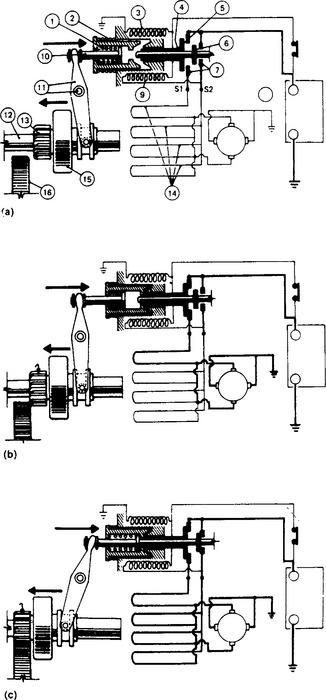
Figure 44.15 Operation of a two-stage switching solenoid: (a) The solenoid is energised in the conventional manner to move the pinion towards the gear ring on the vehicle flywheel: 1, engagement spring; 2, return spring; 3, solenoid hold-on winding; 4, switch-operating spindles (concentric); 5, first set of contacts; 6, second set of contacts; 7, fixed contacts; 8, battery; 9, solenoid operating winder; 10, plunger; 11, operating level and pivot; 12, armature shaft; 13, pinion; 14, field system (four field coils in parallel); 15, roller clutch; 16, gear ring; (b) If tooth-to-tooth abutment occurs, the first set of solenoid contacts close and energise one field coil only, thus giving low power indexing to move the pinion teeth into a meshing position; (c) On full drive engagement, the second set of solenoid contacts close, giving full cranking power. If the pinion teeth, on moving forward, can mesh immediately with the gear ring, full drive engagement takes place with the simultaneous closing of both contacts in the final stage
Two other pre-engaged types of starter are used for heavy compression ignition engines—the coaxial and axial types.
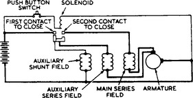
The compact size of the coaxial starter is achieved by mounting a two-stage operating solenoid and switching mechanism inside the yoke, coaxial with the armature shaft. When the starter solenoid is energised, the plunger is attracted into the solenoid, which causes the pinion sleeve and integral pinion to move axially along the armature shaft. At the same time the first-stage contacts close, to energise the starter windings through a built-in resistor (Figure 44.16). The armature rotates under reduced power and the pinion is driven into engagement by means of the armature shaft helix. When the pinion is almost fully engaged, the second-stage contacts close, to cut out the resistor, which enables full power to be developed.
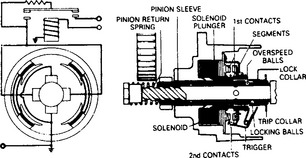
Figure 44.16 Internal wiring and construction of the two-stage switching mechanism of a coaxial starter
The axial starter employs a sliding armature, which is moved axially against spring pressure to bring the pinion into mesh. The starter also has a two-stage switching arrangement (Figure 44.17) to ensure that pinion/ring gear engagement occurs before maximum torque is developed.
44.1.6 Electronic fuel-injection systems
To comply with exhaust regulations and to optimise fuel consumption, the modern petrol engine requires a fuel system of extreme accuracy, reliability and flexibility. To meet this need various electronic fuel injection systems have been developed, the one shown in Figure 44.18 being typical. The system consists principally of an air-flow meter, engine speed sensor, throttle switch, air and coolant temperature sensors, control unit and fuel injectors. Fuel is delivered to the injectors at constant pressure, so that the amount of fuel to be injected is determined solely by the time for which the injectors are held open. Both the time of opening of the injectors and the period for which they are held open are determined by the electronic control unit from the various sensor signals it receives.
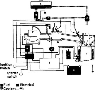
Figure 44.18 Lucas air-flow meter electronic fuel injection system: A, fuel tank; B, fuel pump; C, fuel filter; D, fuel-pressure regulation; E, cold-start fuel injector; F, fuel injector; G, intake manifold; H, extra-air valve; I, cylinder head; J, piston; K, battery; L, relay; M, power resistor; N, ignition coil; O, throttle switch; P, air-flow sensor; Q, coolant-temperature sensor; R, thermo-time switch; S, electronic control limit
Fuel injectors There is one injector per cylinder with each injector clamped between the fuel rail and the inlet manifold. An injector consists of a solenoid-operated needle valve (Figure 44.19). The movable plunger is attached to the needle which is held in the closed position by a helical spring. The solenoid winding is located in the rear of the injector body and may be either 16 or 2.5 Ω resistance, depending upon engine design, size and number of cylinders.
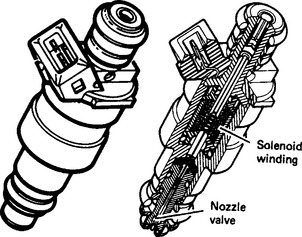
The electronic control unit energises the injector solenoid winding, creating a magnetic field which attracts the plunger away from the nozzle seat. This allows pressurised fuel to flow through the injector via an inbuilt filter, into the inlet manifold.
Injectors should always be replaced at the intervals specified by the vehicle manufacturer.
Air-flow meters: The basic fuel requirement of the engine is determined from engine load data supplied by the air-flow meter, which is situated between the air filter and the induction manifold. In moving flap air-flow meters air flow through the meter deflects a movable flap, which takes up a defined angular position depending upon the force exerted on it by the incoming air. A potentiometer operated by the flap converts the angular position to a corresponding voltage. In the control unit this voltage is divided by engine speed to give the air intake per stroke, from which the basic fuel requirement is then derived.
Since the air-flow meter is used to determine the total mass of air drawn into the engine, adjustments to the basic fuel requirement have to be made for variations in air density (which is temperature dependent). An air temperature sensor is incorporated within the air-flow meter and is connected to the control unit for this purpose.
The hot-wire air-flow meter (Figure 44.20) has a cast alloy body with an electronic module mounted on the top. Air from the air cleaner is drawn through the body of the air-flow meter and into the engine. Some of this intake air flows through a small bypass in which two wires are mounted, a sensing wire and a compensating wire. A heating current is passed through the sensing wire via the electronic module. The compensating wire is also connected to the module, but is unheated.
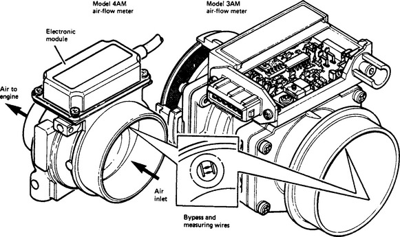
As air is drawn over the wires, a cooling effect occurs which alters the value of the resistance and current in the sensing wire. The compensating wire reacts only to the temperature of the intake air. The electronic module monitors the reaction of these wires, thus measuring the air-flow rate, and sends details of air-flow rate to the electronic control unit.
Note: each air-flow meter module is matched to its sensor and body during manufacture; therefore repair of the unit is not possible if a fault occurs.
Adjustments to the basic fuel quantity are also necessary during engine cranking, cold starting and warm-up, idling, full-load operation and acceleration.
Cranking: During cranking at any engine temperature, a signal from the starter switching circuit is provided to the control unit in order to increase the ‘open’ time of all the injectors above that required to supply the basic fuel quantity.
Cold starting and warm-up: During cold starting a greatly enriched mixture is required to offset the effect of fuel condensing on the walls of the inlet port and cylinders. This extra fuel is provided by a cold-start injector which delivers a finely atomised spray into the inlet manifold. The cold-start injector operates only when the starter is energised and the thermotime (bimetallic) switch—which is sensitive to coolant temperature—completes the electrical circuit. Additional air required during cold starting and warm-up is controlled by an extra-air valve which bypasses the throttle butterfly. The valve aperture is adjusted by the action of a bimetal strip, which is responsive to the combined temperatures of the engine and an internal heater. The valve becomes fully closed when normal running temperatures are reached. During engine warm-up the control unit steadily decreases fuel enrichment in accordance with signals received from the coolant temperature sensor.
Idling, full-load and accelerating modes: In Figure 44.18 a throttle position switch with two sets of contacts is used to signal engine idling or full-load operating conditions to the control unit and thereby obtain the necessary fuel enrichment. Some applications use a potentiometer instead of a throttle switch. Opening of the throttle is then detected by the control unit as an increasing voltage from the potentiometer, causing acceleration enrichment circuits to be triggered.
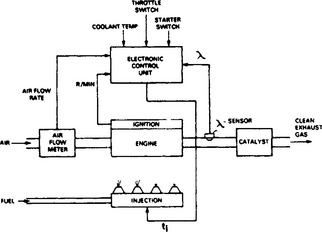
44.1.6.1 Closed-loop electronic fuel injection systems
To obtain the very low exhaust emissions required by stringent legislation, a closed-loop electronic fuel injection system may be employed in conjunction with a three-way exhaust catalyst (Figure 44.21). The catalyst works at optimum efficiency in converting carbon monoxide and hydrocarbon emissions into carbon dioxide and water, and nitrogen oxides into oxygen and nitrogen when the exhaust gases are from an engine operating near to the stoichiometric air/fuel ratio. The operating condition will be indicated by the amount of oxygen present in the exhaust gases, and is monitored in the closed-loop system by an oxygen (lambda) sensor mounted in the exhaust manifold. The sensor provides a feedback signal to the control unit which continuously adjusts the fuelling level to maintain engine operation at the stoichiometric air/fuel ratio.
44.1.6.2 Digital electronic fuel-injection system
Until recently, all electronic fuel injection systems have employed analogue computing techniques. This has meant that for reasons of unit size and cost the complexity of the fuelling schedule stored in the analogue control unit has had to be limited and significant compromises made (Figure 44.22). In contrast, the latest Lucas electronic fuel injection system employs a digital control unit (incorporating large-scale integrated circuits) in which it has been possible to match very accurately the fuel requirements of an engine under all operating conditions: moreover, this has been achieved in a control unit which has a size readily accommodated on the vehicle.
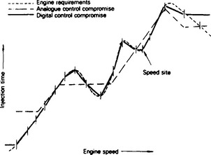
Figure 44.22 Comparison of the fuelling characteristics of analogue and digital systems for a given engine load
A key part of the control-unit information-processing capability is a digital read-only memory (1024 bit) which contains the fuel schedule. The latter is stored as a function of 16 discrete values of engine speed and 8 of load. The fuel requirement at each of these memory sites is identified by an 8-bit number. The fuelling characteristic is smoothed between the points of inflexion (i.e. the discrete value stored at each memory site) by a 32-point interpolation procedure which operates on the load and speed signals to effectively increase the memory size by a factor of 16 × 16.
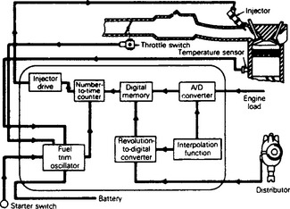
The basic steps in the processing of information within the control unit are shown in Figure 44.23. The engine-speed signal (obtained from the ignition system) and the load signal are each converted into a digital word which is modulated by the interpolation function. The modified numbers representing speed and load are then used to select the site in the memory that stores the fuel requirements for these operating conditions. The memory output number (fuel quantity) is fed into a number-to-time counter, where it is stepped to zero by the fuel trim oscillator. The time taken to count down to zero will therefore be proportional to the memory output and will determine the ‘open’ period of an injector. Signals of air and coolant temperatures and acceleration adjust the fuel quantity read-out of the memory by modifying the frequency of the fuel trim oscillator. The solenoid operated injectors are energised (usually in groups) through power circuits for the countdown period of the number-to-time counter, when fuel is delivered to the engine.
44.2 Light rail transit
Such has been the rapid development of light rail technology that inevitably it has become subject to many misconceptions. It has also been heavily oversubscribed in written terms and has therefore been the subject of transport ‘hype’. It has varyingly been referred to as light weight railway suburban stock at one end of the scale and as an up-market successor to the tram on the other. Whilst in the formative years there is an element of truth in this sort of statement, nevertheless the developing forms of transport have crystallised into its recognisably present status of light rail transit.
Present day light rail transit systems fall into a number of defined categories—the older systems used in many parts of the world (particularly Europe), and the new systems to be found in the UK and the USA, where the public transport renaissance is most marked. These new systems have greatly benefited from the new technologies manifest in traction power supply and collection, suspension and running gear, and control and traction equipment, but in many respects more importantly in the public recognition of the advantages of light rail transit in a country where urban and peri-urban congestion with its environmental pollution, noise, congestion, and attendant loss of working hours has taken dramatic toll of our lifestyles. The new system with light-bodied energy-efficient vehicles and effective operating specification is now firmly established.
The new systems originate from the 1920s and 1930s where, in the UK, design and construction was fragmented and standards were at variance. This situation was rectified in the early 1930s by introducing standard types of tram, mainly as a standardised product in the USA arising from the President’s Conference Committee. The present light rail transit systems are designed to form an integral link within an overall transport system. They will support the distributive role which the motor bus still fulfils and provide a fast and efficient carrier system between centres of population, as well as an interface with heavy rail systems.
44.2.2 Definition
Light rail transit is derived from the old tramway or streetcar systems. These operate mostly on the street in mixed traffic but sometimes also have limited separation from other traffic by preferential treatment at junctions or separate rights of way. Although tramways were almost totally abandoned in the UK, they continued to be developed elsewhere in the world into the higher quality light rail systems. These used higher capacity vehicles which made greater use of separated rights of way outside the central urban areas to avoid road congestion and thus offer shorter journey times. In some instances, separate rights of way were created even within the central areas.
Light rail transit applications range from on-street operation using small vehicles (100 passengers) through to fully segregated operation with large vehicles (200 passengers or more). Light rail transit uses steel-wheeled articulated vehicles propelled by rotary traction motors which normally collect power from an overhead wire at up to 750 V d.c.
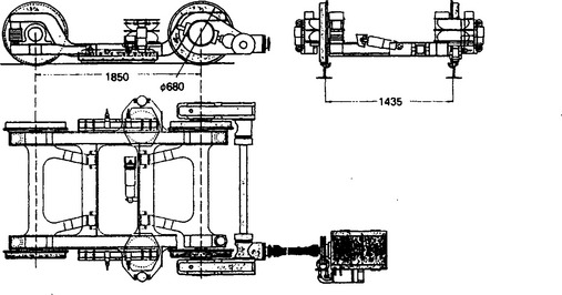
The vehicles may have single or double articulated bodies and may operate in trains of up to four vehicles, limited by station platform length, and by traffic management restrictions on street-running sections. Vehicles are manually driven and may have driving positions at each end, and doors on each side, to permit bidirectional working. Some systems use single-ended vehicles with driving positions at one end and doors on one side only. These offer greater passenger capacity for a given size of vehicle, but require space for turning loops at the ends of the line. Vehicles are usually manually driven, although automatic driving is possible. Vehicles run on conventional railway track of either 1000 or 1435 mm gauge, although new systems almost invariably use 1435 mm (standard gauge). For segregated operation, conventional railway rails and turnouts may be used, although grooved rail and special turnouts are need for street running.
Light rail transit is used in many European cities and elsewhere in the world and is growing in popularity in the UK. At present, for example, there are over 100 systems in the CIS, 58 systems in Germany, 19 in Japan, 14 in the USA, 14 in Romania, 13 in Poland, 10 in Czechoslovakia, 6 in Switzerland, and 5 in each of Austria, France and Italy.
In the UK, Blackpool operates the oldest system on the mainland, being the only remaining tramway system. The Tyne and Wear Metro uses vehicles based on light rail technology, but in most other respects this system is operated like a heavy rail system, being segregated and fully signalled. The original Docklands Light Railway also used vehicles based on light rail technology but was also fully segregated, taking advantage of this segregation to use automatically controlled, driverless vehicles and third rail, low level conductor rails. Following its planned expansion and extension it will become even more atypical.
A scheme has been opened in Manchester; the Midlands Metro has an Act of Parliament for its first line, and has Bills for two further lines currently before Parliament. A system for Sheffield is under construction with a grant from the Department of Transport under Section 56 of the Transport Act. Advanced Transport for Avon has obtained one private Act of Parliament and deposited two further Bills in November 1989. At present in the UK more than 40 other schemes are being considered.
Light rail transit can operate on elevated or in tunnelled sections to provide segregation. However, constructing a new segregated alignment would involve almost as much demolition and land acquisition as building a new road. Elevating the route would add some £7 million to £11 million per double-track kilometre to the capital costs of the system as well as posing severe environmental problems in installing the guideway over existing roads. Tunnelling would cost between £20 million and £30 million per double-track kilometre and, in addition to this civil cost, the system would have to be designed to the same standards as an underground railway from the point of view of safety, which would increase the cost further.
In the UK, HM Railway Inspectorate has defined three types of operation:
(1) LRT1 for street running where light rail vehicles share the carriageway with other road users;
(2) LRT2 for street running where the light rail vehicles run in a road where the track is not shared with other traffic, but is available for use by other road traffic in an emergency; and
(3) LRT3 where the light rail tracks are fully segregated from all other road users.
The main advantages include an ability to move a large volume of people quickly, quietly and comfortably whilst being pollution free at the point of operation. It fills the gap in the transport spectrum between buses and heavy rail, i.e. between about 4000 to 12000 passengers an hour. Its main disadvantage is its inflexibility as it runs on set track, although the tracks themselves do not create a physical barrier to pedestrians crossing the road in street running sections.
44.2.3 Rolling stock
Two typical light rail vehicles are shown in Figure 44.24. Figure 44.24(a) shows a vehicle which is widely used in Germany on systems with extensive street running. It is available in either a single or double articulated form. It is 2.3 m wide and in its single articulated form it is 20 m long overall and accommodates 101 passengers of whom 36 are seated. Figure 44.24(b) shows a larger vehicle which is more widely used on systems which have a higher degree of segregation from other traffic. It has a single articulation and is 2.65 m wide and 27 m long overall. It accommodates 156 passengers of whom 70 are seated. The performance of a typical modern light rail vehicle is summarised in Table 44.1.
Table 44.1
Typical light rail vehicle performance
| Maximum speed | 80 km/h |
| Service speed | 70 km/h |
| Initial acceleration | 1.1 m/s2 |
| Service braking | 1.2 m/s2 |
| Emergency braking | |
| Minimum curve radius in service | 20 m |
| Minimum curve radius in depot | 15 m |
| Maximum gradient | |
| Maximum gradient (all axles motored) |
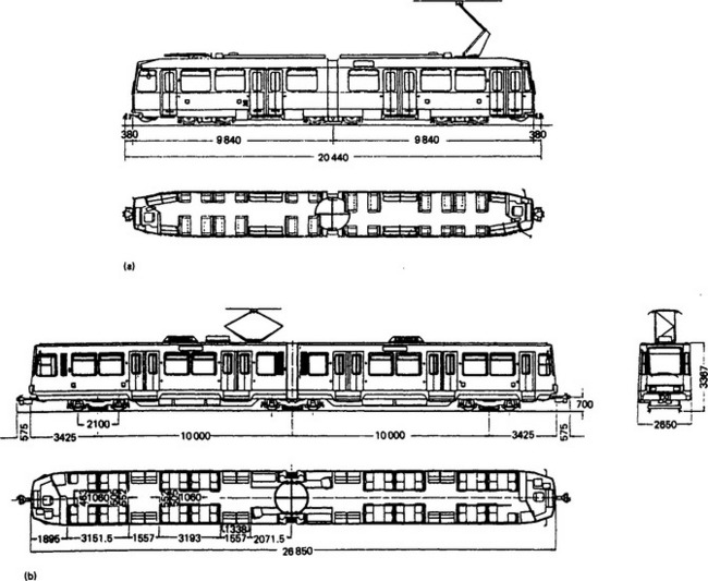
44.2.3.2 Dimensions
Light rail vehicles may be up to 30 m in length overall and the recommended widths are 2.2, 2.4 and 2.65 m. The largest width of 2.65 m permits seating to be arranged two seats either side of central gangway (2 + 2). Narrower widths limit the seating arrangement to 2 + 1. Although the greatest width of 2.65 m is larger than that normally permitted for buses (2.5 m), the fact that the light rail vehicle is guided means that the swept-path needed is no greater than for a bus.
The height from rail to roof ranges between 3.0 and 3.3 m, although in some designs roof-mounted equipment may increase this to over 3.6 m.
44.2.3.3 Passenger capacity
Modern light rail vehicles have nominal capacities ranging from 100 to 250 passengers of whom about one-third would be seated. Traditional light rail vehicles have floor levels about 800 mm above the rail which require the use of high platforms or retractable steps to permit access from street level. High platforms can be difficult to incorporate in existing urban environments and steps present difficulties to the mobility impaired. In the Manchester system light rail vehicles stop with one door alongside a short length of raised platform to provide this access in the street running sections.
The interior of modern vehicles is laid out to accommodate the needs of the mobility impaired with provision for wheelchairs and carefully positioned handles and grab-rails.
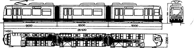
Several manufacturers, including BN, Breda, Duewag and MAN, have developed low-floor vehicles with floor heights between 300 and 350 mm above the rail. These range from conventional vehicles with one section of floor dropped to those providing low floors over their entire length. The latter is generally only achieved at the expense of significant mechanical complication in the design of the bogies and positioning of traction motors, often requiring additional drive shafts and gears. Figure 44.25 illustrates the prototype vehicle developed by MAN for Bremen.
44.2.3.4 Structure
Traditionally, body shells are of light-weight welded steel design in which cable and air ducts, equipment boxes, longitudinal, articulation and end members are welded together to form an underframe. Roof and side-wall frames, fabricated of rolled and bent profiles, are welded together with side-wall sheeting and the underframe to form an integrated structure.
Light alloy construction is also used employing large size extruded sections with pressed on supports for equipment for the side walls, roofs and floors to form an integrated structural unit.
44.2.3.5 Traction and braking equipment
Vehicles are propelled by electric motors which obtain power from an overhead conductor wire via a roof-mounted pantograph.
Most modern light rail vehicles employ d.c. traction motors with d.c.-chopper or a.c.-inverter control both with microprocessor control, although some installations use a.c. induction motors with three-phase inverters.
The motors may be self-ventilated or force ventilated with armatures and field windings insulated with class F or H materials.
Braking is achieved by a combination of rheostatic or regenerative braking by the traction motors combined with friction brakes. For street running, electromagnetic track brakes are fitted to provide an emergency braking rate of about 3 m/s2. Parking brakes are also fitted. Traction and braking systems are integrated to provide:
44.2.3.6 Bogies
Two axle bogies are used. The bogie frames are usually fabricated from steel in a box section design. The frame is supported on the axle boxes by the primary suspension which may consist of chevron-type rubber springs which allow radial adjustment of the wheel sets or of leaf-guided helical or rubber spring elements. Secondary suspension, between the bogie frame and the vehicle body may be by helical, rubber or air springs or by a combination of these. Although the most complex, air springs offer a high ride quality and can maintain the vehicle floor at a constant height above rail level at stops which facilitates level access for mobility-impaired passengers.
There are two general arrangements for motor bogies. In the mono-motor layout a single motor is positioned in the fore-and-aft direction with drive shafts at both ends connected by right-angle gears to the axles. The traction motor and gears form a single unit which is suspended either on the bogie frame or, by means of rubber couplings, on the wheelsets. In the bimotor layout a separate motor is provided for each wheel set and is either hung from the axle or suspended from the bogie frame.
The mono-motor design offers the advantages of lower weight, simpler maintenance and lower cost because of its greater simplicity. A further advantage is that because both axles are connected together wheels cannot begin to spin or slide until all four wheels have lost adhesion. A disadvantage has been that because of restrictions on available space the size, and hence power, of the motor may be limited although recent advances in the design of compact motors has alleviated this to some extent. There is also a suspicion that mono-motor bogies may contribute the phenomenon of rail corrugation in certain circumstances because all wheels are mechanically connected, although the causes of rail corrugation are not well understood.
In addition to rheostatic or generative braking using the traction motor, mechanical brakes are fitted. These may take the form of clasp brakes operating on the wheel treads or disk brakes. Both types are of the spring-applied, power-released type.
Figure 44.26 shows the bogie design used on the MAN low-floor vehicle. The motor is body-mounted and connected to the bogie by a shaft drive with universal joints. Another shaft transmits the power to the two driven wheels because axles are omitted in order to lower the floor.
44.2.3.7 Auxiliary equipment
Folding doors are commonly used which are operated electrically or pneumatically. Retractable steps provide access from street level. Their operation is interlinked with the doors and it is possible to arrange for the steps to operate in different combinations to deal with varying platform heights on different parts of a network. Heating and ventilation are normally fitted.
Automatic couplings can be fitted which will make all necessary mechanical and electrical connections automatically on buffering up two vehicles. Pneumatic uncoupling and central locking can be provided. Where vehicles are not normally operated coupled, provision is made for manual coupling to enable a failed vehicle to be towed or pushed away.
Pneumatic sanders can be fitted for street operation or where steep gradients are encountered.
Auxiliary electrical power supplies are normally fitted for controls, lighting, battery, charging and other purposes. In addition a 24 V d.c. supply is available for control circuits, public address and radio systems, etc. The battery is capable of maintaining emergency lights, public address and radio systems, and marker lights together with local control equipment for a period not less than 1 h.
Miscellaneous equipment normally fitted includes: a public address system to enable the driver to speak to passengers; passenger alarm to allow passengers to attract the driver’s attention; radio equipment to enable the driver to communicate with the controller; route and destination displays; and ticket cancelling or validating machines.
External lighting is fitted generally in accordance with the ‘Construction and Use of Public Service Vehicles’, but taking account of the particular requirements of light rail vehicles. Additional lights may be fitted for operation on fully segregated sections.
44.2.4 Trackwork
On fully segregated sections conventional railway track is generally used. This consists of rails and fixings, generally with sleepers laid on ballast, although it may be convenient in certain areas to fix the rails direct to the supporting structure.
On street-running sections grooved rail is used, set flush into the road surface. The extent of the swept path of the vehicles is indicated by using a different surface texture or colour, or by white lines to highlight the edges as necessary. There are several ways to install the rails in street-running sections. A recently developed method involves providing grooves in the surface. The rails are correctly located to line and level in the grooves before an elastomer material is poured around them. When set this material holds the rails in position yet provides a slight degree of resilience which helps reduce the noise and vibration generated as the vehicle wheels roll over the rail.
Special care must be taken to minimise the effect of stray or leakage traction return current because of the use of d.c, especially in the urban areas. The rails themselves form the immediate return path from the vehicle and thus whatever method of fixing the rails is employed it must provide adequate electrical insulation. The rails themselves are often bonded at frequent intervals to a separate traction return cable. Reinforcing mesh or bars in any concrete slab under the track need to be bonded together and to the traction return cable. In some circumstances it is prudent to insert insulating sections in adjacent water or water pipes, especially those entering buildings, to prevent their being used by stray currents.
Where the line runs in a roadside or other reserve, grassed track can be used. In this, the rails are set flush with the level of the ground which is then grassed between the rails as well as outside them which greatly reduces the visual intrusion.
44.2.5 Power supply
Electrical power is normally obtained from the local electricity supply company; in the UK this is normally at 11 kV a.c. Substations comprising transformer/rectifier units convert this to a lower voltage d.c. This is supplied to the overhead system at a voltage not exceeding 750 V d.c. on the street-running sections, although 1500 V d.c. may be used on segregated sections of the line.
The visual impact of the overhead-line equipment is greatly reduced by the use of insulated support wires made from Parafil which eliminates the need for obtrusive insulators. Wires can also be attached to existing buildings to obviate the need for separate poles. The minimum wire height on street-running sections in the UK is 5.5 m in order to provide safe clearance above other road traffic, but may be reduced to about 3.8 m on fully segregated sections.
44.2.6 Signalling and control
Signalling and control systems permit safe and expeditious operation, while requiring the minimum of manual intervention in normal operation. In street-running sections separate heads are fitted to traffic signals to control the light rail vehicles. These are frequently used to give priority to the light rail vehicles as a means of encouraging the use of public transport. Apart from this, the vehicles are driven like any other road vehicle, with the driver being responsible for maintaining a safe speed.
A form of automatic identification system (such as the Phillips VETAG system) is often fitted to the vehicles. Information about the vehicle’s route may be pre-set so that on approaching junctions the required route may be set automatically and the vehicle given a degree of priority over other traffic. Similarly, line-of-sight operation may be used on partially or fully segregated sections with drivers being responsible for maintaining a safe speed without the need for an elaborate signalling system. Where signalling is needed, at say termini, then a simple, local system can be used.
Mobile radio is normally fitted to the vehicles to enable drivers to remain in contact with a central control room. Staff in the central control room are responsible for the overall supervision of the operation and have good, direct communications to the police, fire and ambulance services for use in case of emergency.
44.2.7 Stops
Stops are simple and unmanned. They basically consist of a raised platform to provide stepless, level entry to the vehicles. If low-floor vehicles are used then on street-running sections the platforms need only be raised some 200–250 mm above the level of the pavement when the height of the kerb is taken into account. Simple passenger shelters only are needed which can also be used to support passenger information notice boards and ticket vending machines selling adult and reduced rate single tickets. Passengers are generally encouraged to purchase multi-journey tickets (carnets), fare cards or reduced-rate tickets off the system.
44.2.8 Depot
The depot provides maintenance facilities for the system and stabling siding for the vehicles. The depot would be equipped to carry out day-to-day servicing and maintenance of vehicles, power supply, signalling, trackwork, etc. Depending on the scale of operation, it may also be equipped to carry out more extensive maintenance work, although it may be found more economical to subcontract certain heavy maintenance of vehicles. One example is turning worn wheels. A wheel lathe for turning wheels in situ on the vehicles costs over £1 million. Facilities provided at the depot typically include: office building; control centre; staff facilities; tracked workshop; general workshop; storage areas for equipment, plant and spares; stabling sidings; washing plant; and external stores compounds.
44.2.9 Economics and investment
In many other countries, public transport is funded by special taxes. In Germany there is a tax on petrol which is designated for roads and public transport, and in France local communities may decide to introduce a payroll tax on employers to fund public transport. In the USA there are a number of State-operated taxes (such as sales taxes) which are used to generate funds. In the UK grants towards construction costs are available from public funds under Section 56 of the Transport Act 1968—half coming from central government and half from local authorities. The grant is only available to fill any gap between the capital cost and the funds available from other sources and must be justified by the economic benefits the system offers to non-users. Primarily this is in terms of time and cost saving to road users who do not use the light rail system.
Light rail transit systems can claim decongestion, and social and environmental benefits which, if quantified, would make the schemes economically viable in cost-benefit terms. Nevertheless, no system recovers its full cost through fares, although direct operating costs which exclude any element of capital charges can be covered. The capital cost of light rail transit varies widely with the type of system, but typically it can vary between £2 million and £3 million per single track kilometre. Similarly, direct operating costs can also vary widely, but in the UK have been estimated to range between £2 and £4 per vehicle kilometre.
44.3 Battery vehicles
For many years, battery-powered vehicles have been used quite extensively in the UK for low-speed, low-range, applications. These vehicles, which use well-proven technology, are described in Section 44.3.1.
Recently, there has been a surge of activity in the development of faster, longer range vehicles, with performance similar to combustion-engine-driven types, and capable of use in commercial fleets or for personal commuting. Such advanced vehicles are not yet fully developed for commercial production, but are expected to be so in the second half of the 1990s. Their current status is described in Section 44.3.2.
44.3.1 Low-speed battery vehicles
The main sphere of use is for local delivery work such as the door-to-door delivery of milk, bread, laundry, coal, mineral waters and other goods, and specialised work such as refuse collection, steel lighting maintenance and interworks transport. In such services a vehicle may be required to make 200–300 delivery stops, while the total distance is usually between 30 and 50 km daily, and rarely reaches the maximum range of about 70 km. Under these conditions the delivery speed and the road speed are almost unrelated, the chief considerations being acceleration, ease of exit and entry to the vehicle, simplicity of control and reduction of personal fatigue. Efficient service is generally obtained with maximum road speeds of the order of 30–35 km/h.
44.3.1.1 Batteries
The lead—acid battery is customary. Choice of battery depends on vehicle duty. Thin-plate automotive starter batteries have high energy capacities but short life on deep-cycling duty. Traction batteries have thicker and firmly separated plates: their weight is kept down by using lightweight plastics cases and short intercell connections. ‘Light traction’ batteries are supposed to withstand 500 charge/discharge cycles, whereas true traction batteries are guaranteed for 1000–1500 cycles, and may last far more. These batteries are most economic (in £/kW-h throughput) if they are used almost daily and discharged to between 70 and 90% of their capacity.
44.3.1.2 Motors
The basic design of d.c. traction motors has not been essentially changed, but the use of improved wires and strips for windings, and class H insulation, have greatly improved thermal transfer and reduced weight.
44.3.1.3 Control
Until the introduction of semiconductors with high current capacity the accepted methods of speed and torque control were (a) series resistance, (b) series/parallel battery switching, (c) series/parallel motor switching and (d) field control. Almost all controllers provided a stepped variation or, at best, a smoothly variable control over limited ranges of torque and speed. The carbon pile variable resistor was also extensively applied, with compression by hydraulic master and slave cylinders.
Series resistance: On small vehicles such as milk prams a single step of resistance usually suffices before the motor is switched on to the full battery, usually 24 V. On larger vehicles and works trucks several steps of series resistance may be used and these are cut out in sequence by a drum or cam controller. The one economical running connection is usually sufficient for low-speed vehicles of the pedestrian-controlled type. In some cases a second economical connection is obtained by field diversion.
Parallel/series battery switching: By dividing the battery into halves, and putting them first in parallel to give half-voltage, then in series to give full voltage, and by using two or three resistance steps for each setting, the loss of energy in the resistors may be halved, compared with the previous system. In addition, an economic half-speed running circuit is obtained. The scheme is also less severe on batteries, since the first few current peaks are shared.
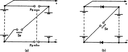
A conventional battery switching circuit employs a pair of contactors interlocked (usually mechanically) so that the double-pole contactor (Figure 44.27(a)) is closed for the parallel and the single pole for the series connection: they cannot be closed at the same time. In a circuit which involves no current breaking (Figure 44.27(b)) diodes make the parallel connections, and the contactor for the series connection reverse-biases the diodes so they do not conduct.
A patented diode/contactor arrangement elaborated from the above gives a multivoltage circuit in which, by contrast with the more obvious battery tapping systems, all batteries are used (not necessarily equally) all the time.
Field control: Field control is fittingly used in addition to the two previous schemes. By use of a four-pole motor with its field windings in separate pairs, full excitation is obtained with the field windings in series, and half-excitation for increased speeds with the field winding pairs in parallel. Field diversion, for even weaker field and higher speed, may be given by shunting an appropriately low resistance across the paralleled field windings.
Solid state switching: With suitable commutation control equipment, thyristors can provide a substantially variable, loss-free motor power control, provided that the pulse rate is not too low. Several forms of pulsed thyristor control are available, differing only in circuit details. The variations are largely associated with the method of providing satisfactory turn-off characteristics for the main circuit thyristors, and correlation of mark/space, repetition frequency and current switching levels to obtain the required motor output characteristics.
Thyristor controllers consist of the following basic elements: (a) main power thyristors, (b) turn-off capacitor; (c) commutator thyristor, (d) function generator, (e) current limiting and fail-safe circuits, and (f) manual control device.
Chopper control In the simplified equivalent circuit shown in Figure 44.28, the switch (Sw) represents the main thyristor in an actual circuit arrangement. In (a) for normal motor operation, Sw is closed for a time t1 and opened for t2 (each time being of the order of a few milliseconds), the sequence being repeated with a switching time T = t1, + t2. During t1 the current rises at a rate proportional to the difference between the battery voltage V and the motor armature e.m.f. E, such that L (di/dt) = V − E, where L is the circuit inductance and resistance is neglected. With Sw now opened for time t2, the motor current continues through the freewheel diode D1, driven by the armature e.m.f. E and falling at a rate such that L(di/dt) = E. Under steady load conditions the rise Δi during the ‘on’ time is equal to the fall Δt during the ‘off’. As the times are short, then approximately
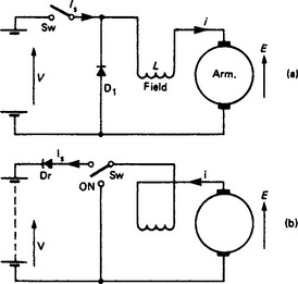
whence E/V = t1/(t1 + t2) = t1/T. The e.m.f. ratio is equal to the ratio between ‘on’ time and total switching period. For an average motor current i the mean battery supply current is Is = i(t1/T) and the mean motor current is Im = Is(T/t1). With E = V(t1/T) it follows that
whence the chopper acts like a ‘d.c. transformer’ in terms of the input and output voltage and current ratios, under steady-state conditions and with resistance and other losses neglected.
In operation, t1/T is increased from zero towards unity to start the motor (with control by the current or voltage limiter). With t1/T = 0.95 or thereabouts, t2 may be too short to allow the thyristor current to quench. In many equipments a contactor is closed to bypass the thyristor and connect the battery direct to the motor, thus eliminating thyristor forward loss.
If sustained low-voltage high-current operation is required (and it is in such a case that the efficiency of the system is much higher than with resistance control), the mean square motor current is higher than the square of the mean current, which raises the motor I2R loss. Enhanced cooling or reduced rating are then necessary in chopper control.
For regeneration the basic circuit is rearranged as in Figure 44.28(b). Diode Dr prevents feedback of the supply to the motor. When Sw is ‘on’, the machine generates, converting kinetic energy into magnetic energy in the inductance; in the ‘off’ time the machine is connected to the supply, and E together with L(di/dt) drives current through Dr into the battery. Then V/E = T/t1 and Is = Im(t1/T).
For control the function generator in the chopper system is combined with comparators to give current and voltage control, switching off when current or voltage attains a demand value. Both values are increased as the ‘accelerator’ pedal is depressed. Regeneration, if fitted, is usually current controlled by the initial movement of the brake pedal, which thereafter applies the friction brakes.
The flexibility of electronic control systems allows the use of a controlled field shunt motor, with electronically controlled field current. Full-field acceleration to the running voltage, with power thyristor control (as above) for the armature current, is followed by controlled field weakening to give, e.g. constant current motoring to a preset speed or the weakest allowable field. Regeneration by field strengthening is then easy to arrange. So far, schemes of this nature have been experimental.
As an example, Figure 44.29 shows in more detail the scheme for chopper control of a battery electric car.
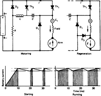
For motoring the battery motor circuit is completed by firing thyristor Th1. The current rises, and at a predetermined value is cut off by the switching action of the current monitor C1. The inductive energy maintains the motor current through the free-wheel diode D1. The current decays, and at a predetermined minimum C1 switches on Th1. The motor current fluctuates between the two limits, but battery current flows only while Th1 conducts. The rate of current fluctuation depends on the armature e.m.f. To switch off Th1 it is necessary to reduce its current momentarily to a very small value by means of Th2, C, L, R and D2. Prior to any current demand, Th2 is switched on and charges capacitor C so that the potential of the left-hand side is raised to that of the positive battery terminal B+ and the right-hand side to that of the negative B-: then Th2 ceases to conduct owing to lack of ‘holding’ current. When Th1 is fired, the right-hand side of C is immediately raised to B+ and the left-hand side to 2B+. Current starts to flow from C through inductor L and diode D2, reducing the voltage across C and increasing the inductive energy in L. When the left-hand side of C has fallen to B+, the current in L continues, which causes a continued fall in the voltage of C. When the current in L has ceased, the left-hand side of C will be at a potential B- and diode D2 becomes reverse-biased. The potentials on C are now B- (left hand) and B+ (right hand), and remain so until Th2 again fires. A bleed path through R ensures that leakage currents through D2 and Th2 do not raise the left-hand voltage on C when Th1 conducts for long periods. When Th2 is fired again, the left-hand side of C is taken up to B+ and the right-hand side to 2B+. The cathode of Th1 is then positive to its anode and it therefore ceases to conduct. The motor current, which is thus transferred from Th1 to Th2, flows through C and lowers the right-hand potential to B-. Then, as the motor current diverts through D1, conduction through Th2 ceases for lack of holding current. The inductive energy of the motor maintains current through D1. The circuit is now ready for Th1 to be fired again.
For regeneration the circuit is set up by changing the armature polarity with respect to the field and by adding diode D3, accomplished by a simple changeover switch. When Th1 conducts, the motor is effectively short-circuited and the current builds up rapidly. At maximum current level Th1 is switched off and the motor current, maintained by the motor inductance, diverts through D1, supplying a charging current to the battery. The cycle repeats to give a roughly constant average motor current and a constant resulting braking torque.
Conditions are complicated by the transition ‘spikes’ of voltage. They have a short duration but a large magnitude. The spikes have some effect on the battery, and increase motor core and I2R losses. They may also impair commutation, particularly at low pulse rate frequency.
The cost of pulsed thyristor equipment is a disadvantage. The reduction of battery energy depends on the type of vehicle and its duty. The overall saving may be about 10% for typical delivery rounds, and rather more for industrial vehicles such as fork-lift trucks.
44.3.1.4 Vehicle and operational details
Charging: Taper chargers are now used extensively for the charging of traction batteries, and are normally provided with germanium or silicon rectifiers. Voltage sensitive thermal relays in conjunction with synchronous timing motors and contactors are used for charge termination. In one form of charge control device a temperature sensitive non-linear resistor, preheated electrically, is cooled by hydrogen from pilot cells when gassing begins. The change in resistance through the cooling of the device causes transductors to regulate the output of the charger.
Improved conductor insulation and high-grade magnetic core material, together with forced cooling, have resulted in weight saving in charger equipments carried on vehicles. A typical charger for connection to a 13 A power outlet, and making full use of this current rating up to the start of the gassing period, has the performance shown in Figure 44.30 when charging a 48 V, 260 A-h lead—acid battery.
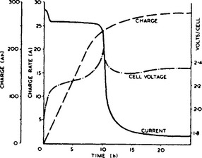
Torque transmission: Most road and industrial battery vehicles are fitted with axles of conventional differential gear design, still the most convenient form of torque transmission to a pair of driving wheels. It has been shown by test that there is scope for improvement in performance by modifying the lubricant viscosity: the axles are normally fitted with extra gear reduction nose-pieces or external chain-and-sprocket reductions, and a fully run-in differential may absorb up to 1.5 kW at maximum road speed. Oils of lower viscosity have been used without excessive gear wear, although the noise is greater.
Hydraulic transmission has found only limited application. Even simple forms cannot compete as alternatives to thyristor motor control gear for driver-type vehicles, but may be suitable for some industrial applications where the infinitely variable characteristic makes elaborate motor control gear unnecessary.
Motorised wheels (i.e. motors built into the wheels) are extensively used in fork-lift trucks, sometimes with low-speed designs of reduced length and increased diameter. The powered wheels can be used for steering, thus improving manoeuvrability.
Regeneration: In general, the small amount of energy recoverable does not warrant the cost and complexity of the control gear necessary for regeneration, although it reduces brake maintenance (a major operating requirement). Certain industrial vehicles such as fork-lift trucks might benefit from regeneration if enough load lowering duty were involved; this might be possible by use of recirculating ball screws in place of the normal hydraulic lifting rams, enabling the motor to generate on lowering.
Tyres: Battery vehicles are affected to a greater extent than other vehicles by the rolling resistance of tyres. Radial ply tyres provide a more supple casing and as a result the loss due to flexing of the walls is less. A saving of 13% in energy consumption (or an increase of 15% in range) can be obtained. An advantage is that radial ply tyres are less sensitive to departures from optimum inflation pressure.
Bodywork: Most recent rider—driver battery vehicles use glass-fibre-resin mouldings, which permit improved appearance with much lower tooling cost. Metal inserts are readily moulded into laminates to provide anchorage points or attachments for components. Translucent panels can be moulded into otherwise opaque surfaces.
44.3.1.5 Applications
Pedestrian controlled vehicles: Bakery and dairy delivery vans, ‘led’ by the driver, have capacities between 0.5 and 11 and a range up to about 20 km. The steering handle carries running and brake controls and there is a separate parking brake. A typical specification includes a 2kW motor, 24 V, 100 A-h battery, and chain or reduction gear differential drive.
Rider—driver vehicles: Invalid carriages with 36 V, 75 A-h batteries have speeds up to 20 km/h and can negotiate any normal road. Municipal vehicles (refuse collection, tower wagons and tractors) are usually 4–6t vehicles with batteries of up to 144 V, 600 A-h. The battery weight is useful in adding stability to the tower wagon. The most widely used industrial trucks are platform, elevating and fork-lift trucks, road and rail tractors, mobile cranes, and trucks for carrying hot forgings and molten metal buckets. The capacities range up to 1–2t. Some lighter types are three-wheelers having the motor and front wheel mounted on a turntable, which makes them exceptionally manoeuvrable.
On elevating, tiering, crane and other types of trucks with power operation, it is usual to employ a separate motor to perform these tasks, power being drawn from the main battery. The location of the battery on the vehicle varies according to the design. On some they are mounted beneath the platform, but in many cases they are mounted on a separate platform or under the driving seat. It is common for these vehicles to work long hours and in such cases two or more sets of batteries are employed, a discharged battery being replaced when necessary. The voltage varies between 24 and 80 V.
When trucks are fitted with a platform for the driver to stand on, steering is usually by means of a tiller, while the controller is hand operated and interlocked with the brake pedal to give a ‘dead man’ effect. With this design the brakes are held off by brake pedal. When pressure on the pedal is released, the brakes are automatically applied and the electric circuit is broken.
Locomotives: Battery shunting locomotives are used by many railways, factories and mines. A typical small locomotive develops a drawbar pull of 1.6 kN (360 lb-ft) at 6.5 km/h from a 4 kW, 48 V totally enclosed series motor with split field windings for control and worm drive on each of the two axles. Such a locomotive is designed for 0.46, 0.51 or 0.61 m gauge. Larger locomotives may weigh up to 81, operate at 120 V, and have two 12 kW series motors with series/parallel control, giving a 1 h tractive effort of 11.5 kN at 8.5 km/h.
44.3.1.6 Electric buses
Two experimental vehicles of the early 1970s demonstrated the feasibility of battery buses. One was a 50-passenger single-deck vehicle, 16 t in weight (including a 4.8 t battery) with chopper control (with regeneration of a 72 kW, 330 V series motor, 64 km range, 64 km/h speed and 1.0 m/s2 acceleration). The other was a ‘minibus’ for 34 passengers in a short single-deck body, with a 100 kW motor, 150 km cruising range, 80 km/h maximum speed, 0.9 m/s2 average acceleration and weight 9.7 t.
From the mid-1970s, several experimental fleets of electric and duo-mode buses were established in Germany as part of a programme initiated by RWE, Germany’s largest privately owned electric utility company. The projects included a fleet of MAN battery electric buses, operating in Münchengladbach and Düsseldorf. The buses were originally designed for rapid battery exchange, to permit extended operation, but were later equipped with rapid recharge facilities at selected bus stops. Although the range on a single charge was only 60 km, these buses were able to achieve 360 km in a 16 h working shift due to ‘opportunity charging’. Other experimental bus fleets were established in France by Renault.
More recently two prototype purpose-designed electric buses with 16-seat capacity have been built by a British company for clients in the USA and Hong Kong, and two 25-seat passenger vehicles have entered service in Santa Barbara, California, as part of an integrated pollution-free pedestrian/public transport scheme in the downtown area.
44.3.1.7 Range and power assessment
The range is limited by the energy/mass storage capability. A 1000 kg lead–acid battery operating at a load of 10–15 kW/t stores about 20 kW-h, and as the transmission efficiency from motor terminals to wheel treads is about 70%, less than two-thirds of the capability is available at the wheels.
A vehicle of weight G with a (battery/total) weight ratio f, driven against a tractive resistance R, has a range S that is roughly estimated from
Let a vehicle have the following particulars:
The tractive resistance R comprises the rolling resistance rr and the air resistance ra. The former is rr = krG, where kr has a value in the range 0.1–0.2. The air resistance, proportional to the square of the speed, is
The drag coefficient ka is 1.0 for bluff-fronted vehicles (e.g. vans), about 0.5 for cars and as low as 0.2 for fully streamlined bodies. The total tractive resistance is then R = (rr + ra), and can be used to estimate the range S (in km).
Let G = 8000 kg, f = 0.25, u = 40 km/h, A = 5.0 m2, kr = 0.15 and ka = 0.78. Then rr = 1200 N, ra = 300 N and R = 1500 N. Then the range S = 67 km.
The power at the wheels (in kW) is P = Ru/3600. For the parameters above, P = 17 kW. The input to the motor is about 17/0.7 = 24 kW. Motor inputs of 8 kW/t may be required for a battery vehicle to emulate an internal combustion-engined vehicle.
If a vehicle is braked to rest from an appreciable speed, the range S is reduced by reason of the loss of kinetic energy in friction. Some allowance may be made by reducing S by about 0.3 km for each brake stop from 50 km/h, and less for lower speeds in proportion to the square of the speed.
44.3.2 Advanced electric vehicles
At the beginning of the 1990s there was a surge of activity world-wide in the development of advanced electric vehicles. The driving force for this activity was mainly concern over atmospheric pollution, particularly in urban areas, and the concern in Western countries about the security of oil supplies, highlighted by the Gulf War of 1991. Increasingly stringent legislation was introduced to limit exhaust-pipe emissions, particularly in the USA where the introduction of zero emission vehicles before the end of century was mandated. As a result, practically all major vehicle manufacturers started development programmes for battery operated vehicles.
44.3.2.1 Advanced batteries
Lead–acid batteries: Modern lead–acid batteries specifically developed for electric vehicle application operate at defined conditions (temperature control, no acid stratification, battery management) and yield between 500 and 1500 duty cycles. Energy density is limited to about 30 W-h/kg, and at the 1–2h rate this often falls below 25W-h/kg. Valve-regulated lead–acid batteries employing gelled electrolyte allow total maintenance-free operation.
Nickel–cadmium batteries: Nickel–cadmium batteries at the 1–2h rate yield twice the energy density of lead-acid batteries, i.e. about 50 W-h/kg. They operate over a wide temperature range, give approximately 2000 cycles, and can be charged in less than 1 h. Nickel–cadmium batteries are used in various developmental electric vehicles. Unfortunately, the high cost of the electrode materials leads to prices 3–4 times higher than lead–acid, only partly offset by longer life.
The presence of cadmium poses a problem with disposal, and development work is in hand to replace the cadmium electrode with a hydrogen-storing electrode, to give the so-called nickel—metal hydride battery. Further developments will lead to a sealed, fully maintenance-free, version.
Sodium–sulphur batteries: A host of other battery technologies are under development, including zinc-bromine, nickel–iron, and various lithium systems. However, it is the sodium sulphur system which is best developed and is now in pilot production by two major European groups. Sodium–sulphur batteries operate internally at temperatures above 300°C and require high-performance thermal insulation. However, they offer energy densities around 100 W-h/kg, fully maintenance-free operation, 100% coulombic efficiency, fast recharge times, good deep discharge performance, and the potential (yet to be proven) for long cycle life and costs similar to lead–acid batteries.
Together with a similar system, sodium–metal chloride, these batteries have been tested in a range of different vehicles in Europe and the USA, and are expected to be in volume production by the mid-1990s.
44.3.2.2 Advanced drive systems
Although d.c. traction motors are still widely used, some vehicle manufacturers are now developing their own a.c. systems which give higher power density. In some designs the motors drive the wheels directly, in others the motor is incorporated into the axle, or drives through a conventional differential.
Advanced electronic controllers are under development which interface with the battery electronics to provide overall system management.
44.3.2.3 Applications
As the technology of electric vehicles improves, the emphasis is switching from commercial delivery vehicles towards personal transport. One US vehicle manufacturer has demonstrated a battery vehicle which achieves 0–60 mile/h in 8 s and has a top speed of 110 mile/h. Several European manufacturers have established small fleets of vehicles, often using conversions of existing models as a ‘mule’ vehicle to test out the drive system. Unless there are unforeseen problems, it can be expected that a new generation of electric vehicles will be on general sale by the middle of the 1990s.
44.4 Road traffic control and information systems
44.4.1.1 Signals
Traffic signal heads usually have two aspects for pedestrians, or three for vehicles with additional aspects for turning movements. Standards exist for colour, light output (typically 400 cd over 30° for good daytime visibility), and sun phantom (the permitted re-emitted level of sunlight).
The aspects are switched on and off at the signal controller via multicore cables, usually at mains voltage. Low-voltage halogen lamps fed by transformers in the signal head are standard in the UK, but mains voltage tungsten lamps are also widely used. High-intensity signals are dimmed at night.
Possible developments include digitally controlled distributed switching having the necessary level of integrity, and solid-state light sources having acceptable colour and intensity.
Primary signals are located at the stop line, on each side of the approach if necessary. Secondary signals are located downstream of the stop line, either on the nearside or the farside of the intersection according to safety considerations.
44.4.1.2 Phasing
Where signal heads control movements which can be started and stopped at the same time they are wired in parallel to a set of controller switches, and form a unit of control known as a ‘phase group’ or ‘signal group’. Phases may be sequential or, providing they do not control conflicting movements, overlap.
To obtain the greatest capacity from the physical intersection space available as many non-conflicting movements are run together as possible, and the sequence of phases is optimised to minimise lost time between movements, taking account of any moves which are prohibited on safety grounds. A simple intersection may have about eight phases and a complex one 24, or more where trams have to be controlled for example.
Where an overall coordination plan is to be followed, for example from a central computer, it may not be necessary to control each phase individually, and phases are grouped into sequential stages such that a new stage is defined whenever a new combination of phases is needed. A normally complete sequence of stages is called a cycle, but stages may be omitted or their order varied according to traffic conditions. Several parallel stage streams (e.g. eight) may be defined in a modern single controller.
A simple three-stage four-phase intersection is shown in Figure 44.31.
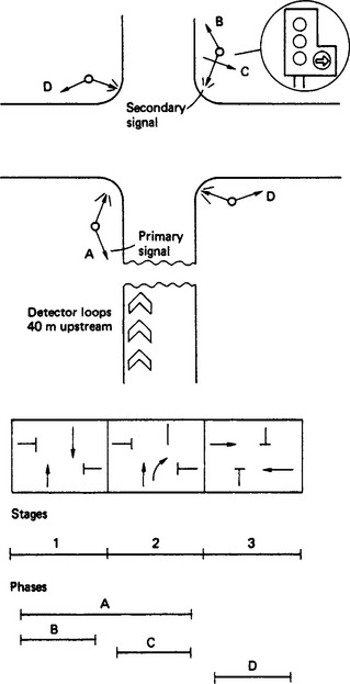
44.4.1.3 Timing
Under vehicle or traffic actuated control, a phase is only called if a demand is received from a vehicle detector, unless it is a phase which must appear. For that phase to begin, conflicting phases must be safely terminated, usually via a leaving amber interval, followed by any all-red period needed to clear conflicting vehicles. In the UK a starting amber is shown before the green signal, which must then run for a minimum green period.
If traffic is still flowing over the detectors at the end of the minimum green interval, extensions of green time occur according to the speed of the vehicles. The phase is terminated when a gap in the extensions occurs or a predetermined maximum green time is reached, provided a demand for a conflicting phase exists.
Under heavier traffic the maximum green times are usually reached. The optimum values must be calculated for the cycle time, and the amount of it which is allocated to each stage in order to minimise overall delay. Although controllers are becoming ‘smarter’, it is usual to pre-calculate the values from surveyed data.
Each approach has an actual flow (q) which must be measured, and a saturation flow (s) which is the maximum that could occur if continuously fed by a queue. Saturation flow is proportional to road width, corrected for gradient.
The ratio y = q/s tells us the claim that each stage will have on the available cycle time. (A narrow road with a large flow has a high y value.) Some of the cycle time is lost (L seconds) to traffic flow during the intergreen period between stages.
The optimum cycle time (co) for minimum delay, e.g. by Webster’s method,1 is approximately
As Y → 1, co → ∞ and a practical limit has to be set at about 120 s. Green times for the stages (the splits) can then be allocated,
A single set of timings may not be appropriate for all peak and off-peak conditions throughout the week. Alternative timing plans (typically eight) are stored in the controller, and selected according to a time-table which is also stored and read in conjunction with a real-time clock. A controller can operate in several modes: fixed time, vehicle (traffic) actuated, police operated, emergency vehicle or rail priority (or pre-empt), or under central computer control.
44.4.1.4 Controller equipment
Historically, a very simple and reliable controller consisted of cam-operated switches driven by a synchronous motor, with dials for alternative timing plans. A modern controller consists of a microprocessor printed circuit board with programmable read only memory (PROM) and battery backed random access memory (RAM) to hold the site configuration data; a user interface to a hand-held terminal or personal computer (PC); interfaces for vehicle detectors; a central computer connection; lamp switching modules (usually triac); and, critically, a secure device to detect the possibility of conflicting green signals.
The whole unit must be relatively cheap, and housed in a weatherproof cabinet with an internal temperature range of at least −15 to +70 °C. Additional features include signal lamp monitoring, and autodialled fault reporting to a central point, strategies which seek to provide better distribution of capacity particularly under heavy traffic conditions.
Autoscheduling is used to help the traffic engineer prepare the considerable amount of data which may be necessary for each intersection, and many features vary from site to site. Controllers such as the GEC GX therefore allow specific values to be attached to the generic values.
44.4.1.5 Vehicle detection
Vehicle detectors most commonly use shallow loops of wire in the roadway whose characteristics at frequencies of around 100 kHz are altered by the presence of vehicles. These detectors are simple, unobtrusive and precise, but demand good installation standards and relatively frequent recutting of the detector loops.
Detection of variations in the earth magnetic field, and piezo/tribo devices to measure mechanical pressure are used less commonly.
Above-surface detectors include microwave, infra-red and ultrasonic measurement of reflected energy. Structures are needed near to the point of detection at a suitable height and position to avoid vehicle obscuration. Video-image processing is used for incident detection.
44.4.1.6 Signal coordination
Where the travel time between intersections is short enough for traffic platoons not be become unduly dispersed (e.g. about 30 s or less), it is beneficial to co-ordinate the time between the appearance of successive green signals, known as the ‘offset’.
This can be done locally for small groups of intersections by synchronising the controller real-time clocks to the mains power frequency. The initial reference is set up manually, or using the dial-up remote monitoring equipment.
44.4.2 Traffic control systems
44.4.2.1 Urban traffic control
Urban traffic control (UTC) systems use central computers to co-ordinate and monitor larger numbers of intersections, from typically 15 up to thousands of intersections in a complete metropolitan area.
Optimisation of signal settings for minimum overall delay in two-dimensional networks is traditionally done off-line using surveyed traffic flows and a method such as TRANSYT.2 Fixed time plans are then loaded into the control computers together with a time-table as described for the controller. At least 15% overall reduction in journey times should be achieved.
The computer sends stage-by-stage change messages to each controller, with typically eight on one 1200 bits per second (bps) communication channel, and checks that the controllers have responded.
Plans may be changed by operators in a control room to suit abnormal traffic conditions, using closed-circuit television to monitor key intersections. It is difficult to quantify the benefits of manual intervention in terms of traffic measurements, but the cost of surveillance equipment is often justified in terms of the overall savings from the scheme.
Fixed time plans typically require updating after about 3 years if the initial benefits are not to deteriorate. Fully traffic adaptive systems such as SCOOT are now standard which, second by second, optimise splits, cycle time and offset from real-time traffic measurements. The principle is illustrated in Figure 44.32.
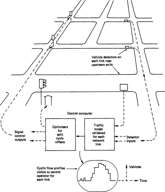
A standard system such as the GEC Traffic Management System combines SCOOT with car-park and diversion-sign control, emergency vehicle priority, and the ability to preprogram operator actions for holidays, etc. More central computing cells and operator PCs are simply added to the central local area network in order to control larger numbers of intersections.
44.4.2.2 Motorway control
Roadside communication devices along a longitudinal cable, a central computer system and control centres are also used for motorway surveillance and control. The most basic requirement is for emergency telephones, which in some countries use solar power and radio.
Sign control is primarily for access and hazard warning. Ramp metering is a method of dynamic access control used to feed joining traffic onto the motorway. Signs may be used to close ramps in emergencies, and re-route traffic in conjunction with the UTC system in urban areas.
Hazard warnings on the motorway must be rapid and relevant, and are demanding in terms of closely spaced signs, vehicle and weather detection, and a reliable, fast and automatic incident detection algorithm. Their justification (by comparison with lighting, for example) must be set against relatively infrequent, but major, accidents.
44.4.3 Driver information systems
Traffic control schemes seek to make the best use of existing roadspace, but they can only respond to demand on the network resulting from drivers’ route choice. This, in turn, is based on imprecise information about up-to-the-minute traffic conditions.
In a scheme such as GEC Autoguide, and its German equivalent Euroscout, drivers receive junction by junction routing information on a relatively cheap in-vehicle unit, based on up to the minute traffic data held in a central computer. Users help to gather this data, without revealing their identity, by giving their travel times for each network link back to the system. The principle is illustrated in Figure 44.33.
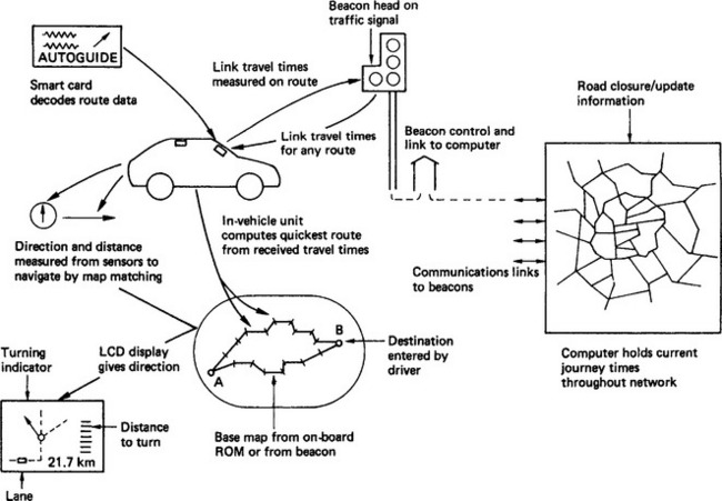
Other types of system provide traffic information without alternative routing advice, or provide in-car map-following navigation without live traffic data.
In Autoguide type systems information is exchanged with roadside beacons using infra-red or microwave transmission, or by cellular radio, preferably to digital standards with a broadcast channel. The vehicle is fitted with sensors to measure the direction and distance travelled, and uses map matching to correct its position. Beacon density follows network density, and is governed by the need to provide sufficiently frequent updates of journey times and map information.
44.4.3.2 Added value information
Information is purchased in a commercial system by buying a smart card which enables the in-vehicle system to decode the received data. This can include parking availability or other added value information. The roadside/vehicle communication infrastructure can also be used for vehicle location, bus information, etc.
Relatively simple in-vehicle satellite terminals are also used for location and messaging, and are well suited to providing guidance information over longer distances.
44.4.3.3 Tolls and road pricing
The combination of a vehicle-to-roadside link and smart-card technology also enables prepayment for the use of roadspace without stopping, e.g. for toll roads or road pricing in a city area.
Identification of non-paying users is achieved by detectors which can locate precisely the position of vehicles in the carriageway, and capturing video frames showing the registration numbers.
44.4.3.4 Intelligent vehicle/highway systems
Intelligent vehicle/highway systems (IVHS) are enabling transport information and control systems to become fully integrated, to include pre-trip planning by phone or teletext, route guidance, hazard warning, passenger information, parking availability, etc.
1. Transport And Road Research Laboratory, Technical Paper No. 56, 1966.
2. Transport And Road Research Laboratory, Transyt 9 User Manual-Applications Guide No. 8, 1988.
BS 2 (SBN 580 00500 3) Tramway and dock rails and fishplates
BS 173 (SBN 580 00592 5) Rotating electrical machines for use on road and rail vehicles
BS 1727 (SBN 580 06861 7) Motors for battery operated vehicles (N.B. not rail vehicles)
BS 2550 (SBN 580 06249 X) Lead-acid traction batteries for battery electric vehicles and tracks
BS 2618 (ISBN 0 580 08473 6) Electric traction equipment
BS 4846 (ISBN 0 580 07387 4) Resistors for traction purposes (N.B. not road vehicles)