Dip-Meter Circuits
The sources of the following circuits are contained in the Sources section, which begins on page 217. The figure number in the box of each circuit correlates to the source entry in the Sources section.


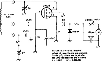
LITTLE DIPPER

The circuit consists of two basic circuits, the oscillator and the detector. The oscillator uses an FET in a Colpitts configuration. The energy circulating in the oscillator tank is coupled through C4 to the detector circuit, where a small diode (D2) rectifies it and feeds a dc voltage to the Darlington pair (Q2, A3) controlled by the sensitivity control (R3). Any small variations in the bias of the amplifier will cause large variations of current through the LED indicator in the DIP mode; however, in the PEAK mode the current produces a corresponding voltage drop through R5 and the action of the LED is reversed. The circuit shown will work practically on any frequency from LF to VHF, if the appropriate components are used.