Field-Strength Meter Circuits
The sources of the following circuits are contained in the Sources section, which begins on page 217. The figure number in the box of each circuit correlates to the source entry in the Sources section.
LF OR HF FIELD-STRENGTH METER
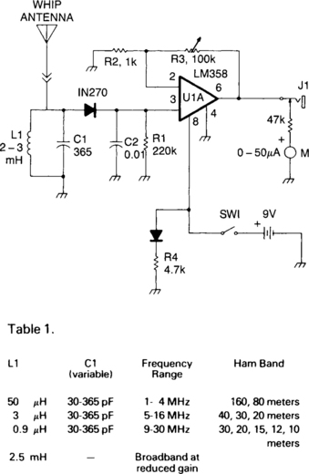
C1 and L1 resonate in the 1750-meter band, with coverage from 150 to 500 kHz. L1 can be slug-tuned for 160- to 190-kHz coverage alone or a 2.5-mH choke can be used for L1, if desired, using C1 for tuning. A 1N270 germanium diode rectifies the RF signal and C2 is charged at the peak RF level. This dc level is amplified by an LM358. The gain is determined by R2 and R3, one 100-kΩ linear potentiometer that varies the dc gain from 1 to 100, driving the 50 mA meter. This field-strength meter need not be limited to LF use. The Table shows the L1 and C1 values for HF and broadband operation.
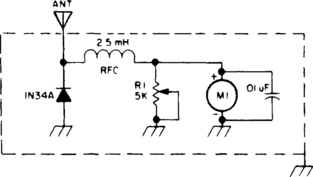
TUNED FIELD-STRENGTH METER

A resonant combination of Ll and Cl is selected to cover frequencies desired.

RF SNIFFER

This circuit responds to RF signals from below the standard broadcast band to well over 500 MHz, and provides a visual and audible indication when a signal is received. The circuit is designed to receive low-powered signals as well as strong sources of energy by adjusting the bias on the pick-up diode, D1, with R2. A very sensitive setting can be obtained by carefully adjusting R2 until the LED just begins to light and a faint sound is produced by the piezo sounder.
SENSITIVE FIELD-STRENGTH METER
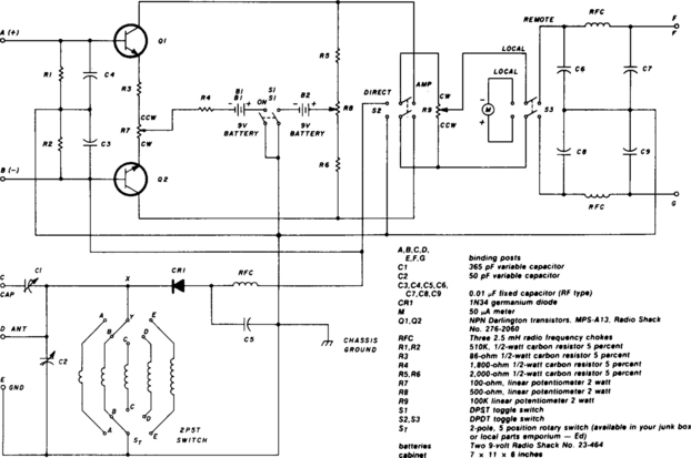
The two-pole, five-position switch, coils, and 365-pF variable capacitor cover a range from 1.5 to 30 MHz. The amplifier uses Darlington npn transistors whose high beta, 5000, provides high sensitivity with S1 used as the amplifier on/off switch. Switch S2 in the left position allows the output of the 1N34 diode to be fed directly into the 50-μA meter (M) for direct reading. When S2 is in the right position, the amplifier is switched into the circuit. Switch S3 is for local or remote monitoring. At full gain setting, the input signal is adjusted to give a full-scale reading of 50 mA on the meter. Then, with the amplifier switched out of the circuit, the meter reading drops down to about 0.5 mA. A 2.5-mH RF choke and capacitors C3, C4, and C5 effectively keep RF out of the amplifier circuit.
FIELD-STRENGTH METER I

The untuned, but amplified, FSM can almost sense that mythical flea’s whisper—from 3 through 148 MHz no less—and yet, is so immune to overload that the meter pointer won’t pin. The key to the circuit is the amplifier, a 324 quad op amp, of which only one section is used. It’s designed for a single-ended power supply, will provide at least 20-dB dc gain, and the output current is self-limiting. The pointer can’t be pinned.
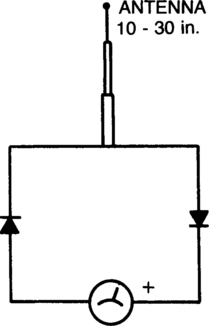
FIELD-STRENGTH METER II
The antenna consists of about 20 cm of insulated stranded wire glued or taped around the inside of a small plastic box. The RF current is rectified by two diodes, and a 10-kΩ potentiometer provides variable attenuation for the meter.

FIELD-STRENGTH METER III

A “minimum-parts” field-strength meter is shown here. For more distant testing, add the dc amplifier.

RF-ACTUATED RELAY

Automatic antenna switching or RF power indication can be achieved with this circuit. Relay will key with less than 150 mW drive on 2 m.
ON-THE-AIR INDICATOR

The circuit is a simple RF-actuated switch which will respond to any strong field in the region of the pickup wire. The length of the wire will depend on how much coupling is needed, but a 250-mm length wrapped around the outside of the coaxial cable feeding the antenna should suffice for most power levels. If only one band is used, the wire can be made a resonant length—495 mm for 144-MHz band operation, for example. When RF energy is picked up by the device, diode D1 will conduct on the negative half-cycles, but will be cut off on the positive half-cycles. The result will be a net positive voltage at the base of transistor Tr1, forward biasing it into conduction. On SSB and cw transmissions, where the transmission is not continuous, that bias would be constantly varying and the relay RLA would chatter. However, capacitor C2 holds the bias voltage steady until a long gap in transmissions occurs.
HIGH-SENSITIVITY FIELD-STRENGTH METER

A TL081 (IC1 op amp) is used to increase sensitivity. The RF signal is detected by CR1 and is then amplified by IC1. Full-scale sensitivity is set with the 100-kΩ potentiometer.
TRANSMISSION INDICATOR
Every time the push-to-talk button is closed the light will go on. The antenna samples the output RF from the transmitter. That signal is then rectified (detected) by germanium diode D1, and used to charge capacitor C2. The dc output is used to trigger a small silicon-controlled rectifier (SCR1), which permits the current to flow through the small pilot lamp. For lower-power applications, such as CB radio, the indicator antenna will have to be close-coupled to the transmitter antenna.

ADJUSTABLE-SENSITIVITY FIELD-STRENGTH INDICATOR
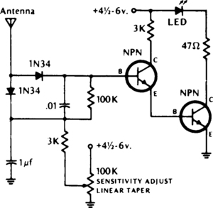
The LED lights if the RF field is higher than the preset field strength level. Diodes should be germanium. Transistors (npn)-2N2222, 2N3393, 2N3904 or equivalent.
SIMPLE FIELD-STRENGTH METER
The circuit is not frequency selective. It has been used from 2 meters through 160 meters. The telescoping antenna may be adjusted to its shortest length when working at 2 meters to keep the needle on the scale. Meter should be a 100- to 500-µA movement. The diodes are germanium, such as the 1N34, etc. Silicon diodes will also work, but they are a bit less sensitive.