Temperature Measuring Circuits
Digital Temperature-Measuring Circuit
Basic Digital Thermometer (Kelvin Scale)
Basic Digital Thermometer (Kelvin Scale with Zero Adjust)
Simple Differential Temperature Sensor
Dual-Output Over-Under Temperature Monitor
Thermocouple Amplifier with Cold-Junction Compensation
Centigrade-Calibrated Thermocouple Thermometer
μP-Controlled Digital Thermometer
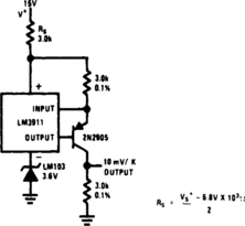
Precision Temperature Transducer with Remote Sensor
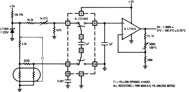
5-V Powered, Linearized Platinum RTD Signal Conditioner
Curvature-Corrected Platinum RTD Thermometer
Temperature Sensor and DVM Interface
Implantable, Ingestible Electronic Thermometer
Temperature-Measuring Add-On for a DMM
Four-Channel Temperature Sensor (0 to 50°C)
Basic Digital Thermometer (Celsius and Fahrenheit)
Temperature-Reporting Digital Thermometer
Ground-Referred Centigrade Thermometer I
Ground-Referred Centigrade Thermometer II
Positive Temperature Sensor Coefficient Resistor
Differential Temperature Sensor
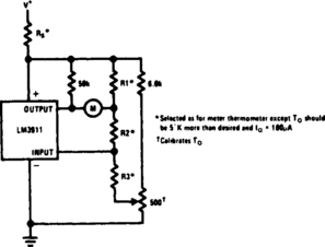
Meter Thermometer with Trimmed Output
The sources of the following circuits are contained in the Sources section, which begins on page 217. The figure number in the box of each circuit correlates to the source entry in the Sources section.
DIGITAL TEMPERATURE-MEASURING CIRCUIT
The output voltage of a thermocouple is converted into frequency, measured by a digital frequency meter. The measuring set, connected with Ni-NiCr thermocouple, permits you to measure the temperatures within the range of 5 to 800°C with ±1°C error. The output thermocouple signal is proportional to the temperature difference between the hot junction and the thermostat. Kept at 0°C, the thermostat drives the voltage-to-frequency converter, changing the analog input signal into the output frequency with the conversion ratio adjusted so that the frequency is equal to the measured temperature in Celsius degrees (e.g., for 350°C the frequency value is 350 Hz).
BASIC DIGITAL THERMOMETER (KELVIN SCALE)
The Kelvin scale version reads from 0 to 1999°K theoretically, and from 223°K to 473°K actually. The 2.26-kΩ resistor brings the input within the ICL7106 VCM range: two general-purpose silicon diodes or an LED can be substituted.

BASIC DIGITAL THERMOMETER (KELVIN SCALE WITH ZERO ADJUST)
This circuit allows zero adjustment as well as slope adjustment. The ICL8069 brings the input within the common-mode range, while the 5-kΩ pots trim any offset at 218°K (–55°C), and set scale factor.


DIGITAL THERMOMETER

The sensor consists of two series-connected lN914s, part of the circuit of a 555 multivibrator. Wired as shown, the output pulse rate is proportional to the temperature of the diodes. This output is fed to a simple frequency-counting circuit.
TEMPERATURE METER

TCA965 window-discriminator IC allows the potentiometers RV1 and RV2 to set up a window height and window width, respectively. R1 and thermistor TH1 for a potential divider connected across the supply lines. R1 is chosen such that at ambient temperature the voltage at the junction of these two components will be approximately half supply. As the temperature of the sensor changes, the voltage will change. RV1 will set the point that corresponds to the center voltage of a window the width of which is set by RV2. The switching points of the IC feature a Schmitt characteristic with low hysteresis. The outputs of IC1 indicate whether the input voltage is within the window or outside by virtue of being either too high or too low. The outputs of IC1 drive the LEDs via a current-limiting resistor.
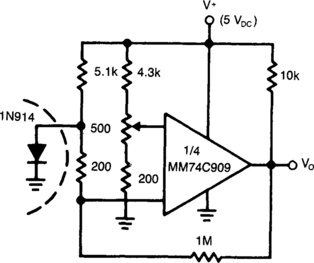
0 to 63°C TEMPERATURE SENSOR

The temperature sensor provides an input to pin 3 of the NE5037 of 32 mV/°C. This 32 mV is the value of one LSB for the NE5037. The LM334 is a three-terminal temperature sensor and provides a current of 1 μA for each degree Kelvin. The 32-kΩ resistor provides the 32 mV for each microamp through it, while the transistor bleeds off 273 μA of the temperature sensor (LM334) current. This bleeding lowers the reading by 273 K, thus converting from Kelvin to Celsius. To read temperature, conversion is started by sending a momentary low signal to pin 7 of the NE5037. When pin 10 of the NE5037 becomes low, conversion is complete and a low is applied to pin 9 of the NE5037 to read data on pins 11 through 16. Notice that this temperature data is in straight binary format. The controller can be a microprocessor in a temperature-control application, or discrete circuitry in a simple temperature-reporting application.
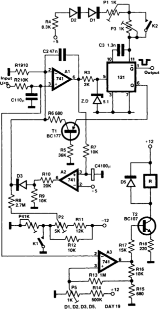
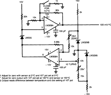
DUAL-OUTPUT OVER-UNDER TEMPERATURE MONITOR

This circuit is ideal for use as an over-under temperature monitor, where its dual output feature can be used to drive high and low temperature indicator lamps, relays, etc. T1 is a 6.3-V filament transformer whose secondary winding is connected inside of a four-arm bridge. When the bridge is balanced, ac output is zero, and C5 (or C7) receives no gate signal. If the bridge is unbalanced by raising or lowering the thermistor’s ambient temperature, an ac voltage will appear across the SCR’s gate cathode terminals. Depending on which sense the bridge is unbalanced, the positive gate voltage will be in phase with, or 180° out of phase with the ac supply.
If the positive gate voltage is in phase, the SCR will deliver load current through diode CR1 to load 1, diode CR2 blocking current to load 2. Conversely, if positive gate voltage is 180° out of phase, diode CR2 will conduct and deliver power to load 2, CR1 being reverse biased under these conditions. With the component values shown, the circuit will respond to changes in temperature of approximately 1 to 2°C. Substitution of other variable-resistance sensors, such as cadmium sulfide light-dependent resistors (LDR) or strain-gauge elements, for the thermistor shown is permissible.
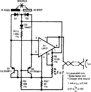
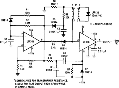
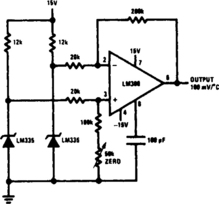
THERMOCOUPLE AMPLIFIER WITH COLD-JUNCTION COMPENSATION

Input-protection circuitry allows thermocouple to short to 120 Vac without damaging the amplifier. Calibration:


HIGH/LOW TEMPERATURE SENSOR
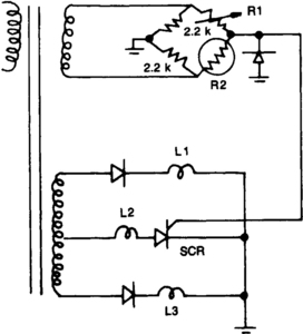
Resistors R1, R2, and the two 2.2-kΩ resistors form a bridge circuit. R2 is a thermistor, and R1 sets the temperature at which L2 lights. Lower or higher temperatures light L1 or L3 to indicate an over- or under-temperature condition.
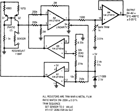
CURVATURE-CORRECTED PLATINUM RTD THERMOMETER

This thermometer is capable of 0.01°C accuracy over −50 to +150°C. A unique trim arrangement eliminates cumbersome trim interactions so that zero gain, and nonlinearity correction can be trimmed in one even trip. Extra op amps provide full Kelvin sensing on the sensor without adding drift and offset terms found in other designs. A1 is configured as a Howland current pump, biasing the sensor with a fixed current. Resistors R2, R3, R4, and R5 form a bridge driven into balance by A1. In balance, both inputs of A2 are at the same voltage. Because R6 = R7, A1 draws equal currents from both legs of the bridge. Any loading of the R4/R5 leg by the sensor would unbalance the bridge; therefore, both bridge taps are given to the sensor open-circuit voltage and no current is drawn.
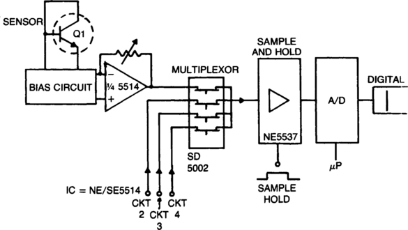
THERMOCOUPLE MULTIPLEX SYSTEM

To decouple the sensors from the meter amplifier, either a reference junction at 0°C or a bucking voltage set at room temperature can be used. The latter method is simpler, but is sensitive to changes in ambient temperature. The table above shows the output voltage vs temperature of several common types of thermocouples.
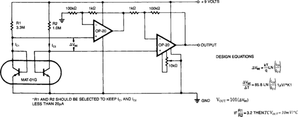
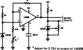
TEMPERATURE SENSOR AND DVM INTERFACE
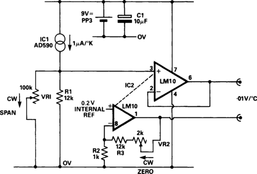
The DVM gives a direct indication of the temperature of the sensor in degrees Centigrade. The temperature sensor IC1 gives a nominal 1 μ? per degree Kelvin, which is converted to 10 mV per degree Kelvin by R1 and VR1. IC2 is a micropower, low-input drift op amp with internal voltage reference and amplifier. The main op amp in IC1 is connected as a voltage follower to buffer the sensor voltage at R1.
The second amplifier in IC1 is used to amplify the 0.2 V internal reference up to 2.73 V in order to offset the 273° below 0°C. The output voltage of the unit is the differential output of the two op amps and is thus equal to 0.01 V per °C.
IMPLANTABLE, INGESTIBLE ELECTRONIC THERMOMETER

This oscillator circuit includes a quartz crystal that has a nominal resonant frequency of 262, 144 Hz and is cut in the orientation that gives a large linear coefficient of frequency variation with the temperature. In this type of circuit, the oscillation frequency is controlled primarily by the crystal—as long as the gain-bandwidth product is at least four times the frequency. In this case, the chosen component values yield a gain-bandwidth product of 1 MHz. Inductor L1 can be made very small: 100 to 200 turns with a diameter of 0.18 in. (4.8 mm) and a length of 0.5 in. (12.7 mm). Although the figure shows two transistors in parallel, one could be used to reduce power consumption or three could be used to boost the output. The general oscillator circuit can be used to measure temperatures from −10 to + 140°C. A unit made for use in the human body from about 30 to 40°C operates at 262,144 ± 50 Hz with a frequency stability of 0.1 Hz and a temperature coefficient of 9 Hz/°C.
TEMPERATURE-MEASURING ADD-ON FOR A DMM
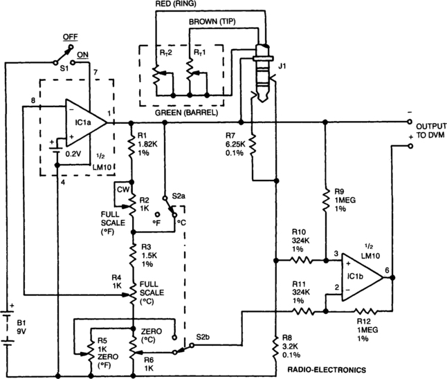
The DVM-to-temperature adapter is built around a single IC, National’s LM10. That micropower IC contains a stable 0.2-V reference, a reference amplifier and a general-purpose op amp. The circuit is designed for a linear temperature range of 0 to 100°C (32 to 212°F). The 0.2-V reference and reference amplifier provide a stable, fixed-excitation voltage to the Wheatstone bridge. The voltage is determined by a feedback network consisting of R1 through R6. Switch S2a configures the feedback to increase the voltage from 0.6 V on the Celsius range to 1.08 V on the Fahrenheit range. These differences compensate for the fact that one degree Fahrenheit produces a smaller resistance change than does one degree Celsius.
Resistors R1 through R16 also form the fixed leg of the Wheatstone bridge, nulling the bridge output at zero degrees, because 0°C is different from 0°F, S2b is used to select the appropriate offset.
The LM10’s op amp, along with R9 through R12, form a differential amplifier that boosts the bridge output to 10 mV per degree. Since a single supply is used, and since the output must be able to swing both positive and negative, the output is referenced to the bridge supply voltage, rather than to the common supply.

BASIC DIGITAL THERMOMETER (CELSIUS AND FAHRENHEIT)
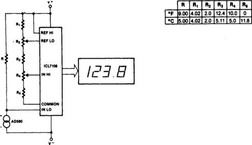
Maximum reading on the Celsius range is 199.9°C, limited by the (short-term) maximum allowable sensor temperature. Maximum reading on the Fahrenheit range is 199.9°F (93.3°C), limited by the number of display digits. VREF for both scales is 500 mV.

DIFFERENTIAL THERMOMETER

The differential thermometer uses two probes and shows the temperature difference between them, rather than the exact temperature. The thermometer uses a conventional meter as an indicator, and it covers a total range of 20° – 10° low to 10° high.
TEMPERATURE-REPORTING DIGITAL THERMOMETER
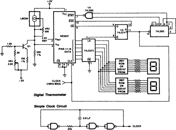
The ROMS or PROMs must have the correct code for converting the data from the NE5037—used as address for the ROMs or PROMs—to the appropriate segment driver codes. The displayed amount could easily be converted to degrees Fahrenheit, °F, by the controller of (0 to 63° temperature sensor) or through the (P)ROMs. When doing this, a third (hundreds) digit (P)ROM and display will be needed for displaying temperatures above 99°F. An expensive clock can be made from NAND gates or inverters, as shown.
ELECTRONIC THERMOMETER
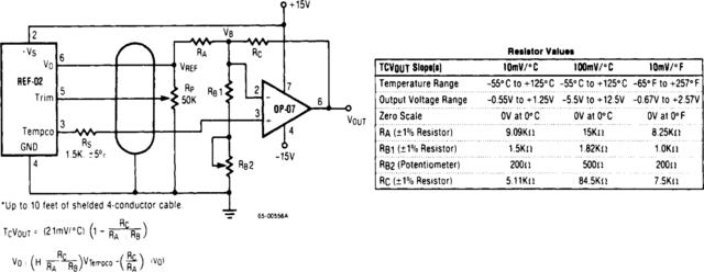
This circuit uses the + 5-V reference output and the op amp to level shift and amplify the 2.1-mV/°C Tempco output into a voltage signal dependent on the ambient temperature. Different scaling can be obtained by selecting appropriate resistors from the table giving output slopes calibrated in degrees Celsius or degrees Fahrenheit. To calibrate, first measure the voltage on the Tempco pin, VTEMPCO, and the ambient room temperature, TA in °C. Put those values into the following equation:
Where S = Scale factor for your circuit selected from the table in mV. Then, turn the circuit power off, short VOUTat pin 6 of the REF-02 to ground, and while applying exactly 100.00 mV to the op amp output, adjust RB2 so that VB = (X) (100 mV). Now remove the short and the 100-mV source, reapply circuit power and adjust RP so that the op-amp output voltage equals (TA) (S). The system is now exactly calibrated.


SIMPLE LINEAR THERMOMETER
The thermistor network specified eliminates the need for a linearity trim—at the expense of accuracy and operational range.
THERMOMETER ADAPTER
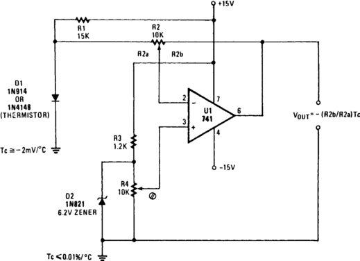
A simple op amp and silicon diode are the heart of the temperature-to-voltage converter that will permit you to use an ordinary voltmeter—either analog or digital—to measure temperature. User adjustments make it possible for a reading of either 10 mV or 100 mV to represent 1°F or C.
Temperature sensor D1 is a 1N4148 silicon diode. It has a temperature coefficient of −2 mV/°C. U1, a 741 op amp, is connected as a differential amplifier. A voltage divider consisting of R3 and Zener diode D2 provides a 6.2-V reference voltage. D2 is shunted by potentiometer R4, so that the offset can be adjusted to align the output voltage with either the Celsius or Fahrenheit scale, as desired.
Gain control R2 is adjusted so that the output of the op amp is in the scale or voltage range of the meter being used. R4, the offset-adjust control, is then adjusted so that the output voltage represents either degrees F or C. The thermometer adapter can be calibrated by adjusting R4 while the probe sensor is at a known temperature.

