Resistance and Continuity-Measuring Circuits
The sources of the following circuits are contained in the Sources section, which begins on page 217. The figure number in the box of each circuit correlates to the source entry in the Sources section.
SIMPLE RATIOMETRIC RESISTANCE MEASURER

The unknown resistance is put in series with a known standard and a current passed through the pair. The voltage developed across the unknown is applied to the input and the voltage across the known resistor applied to the reference input. If the unknown equals the standard, the display will read 1000. The displayed reading can be determined from the following expression:
AUDIO CONTINUITY TESTER

This low-current audio continuity tester indicates the unknown resistance value by the frequency of the audio tone. A high tone indicates a low resistance, and a tone of a few pulses per second indicates a resistance as high as 30 MΩ.
LINEAR-SCALE OHMMETER I

One preset resistor is used for all the ranges to simplify the setup. Diode clamping is included to prevent damage to the meter if the unknown resistor is higher than the range selected. When the meter has been assembled, a 10-kΩ precision resistor is placed in the test position, Rx; the meter is set to the 10-kΩ range and RV1 is adjusted for full-scale deflection.
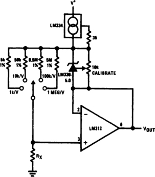
LINEAR-SCALE OHMMETER II
This circuit is designed to provide accurate measurement and a linear-resistance scale at the high end. The circuit has four ranges. Another meter with a current range of 10 μA to 10 mA and sensitivity of 10,000 Ω/V is needed for setting up.

OHMMETER
This circuit has a linear-reading scale, requires no calibration, and requires no zero adjustment. It can be made multirange by switching in different standard resistors.
CABLE TESTER

This compact tester checks cables for open-circuit or short-circuit conditions. A differential transistor pair at one end of each cable line remains balanced as long as the same clock pulse generated by timer IC appears at both ends of the line. A clock pulse, just at the clock end of the line, lights a green LED, and a clock pulse, only at the other end, lights a red LED.
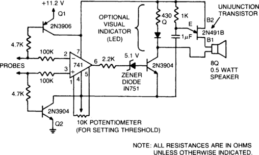
ADJUSTABLE, AUDIBLE CONTINUITY TESTER FOR DELICATE CIRCUITS

The tester gives an audible indication, making it unnecessary for the user to look directly at the instrument to observe a meter reading. In addition, the current and voltage of the tester are strictly limited. It can apply no more than 0.6 Vdc and no more than 3 mA through the probes. It can therefore be used safely on circuit boards in which semiconductor components have been installed, and on complementary metal oxide/semiconductor integrated circuits, which are highly susceptible to damage during testing. The tester can be adjusted to indicate continuity below any resistance value up to 35 Ω. For example, if the user sets the tester to 30 Ω, the unit will emit an audible tone whenever the resistance between the probes is 30 Ω or less; if, for example, the resistance is 30.2 Ω, the unit will remain silent.
CONTINUITY TESTER
The continuity tester feeds a voltage through the positive probe to the circuit under test, while the negative probe serves as the return line. Voltage that returns to the tester through the negative probe triggers the circuit, giving an audible indication of continuity.
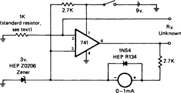
LOW-RESISTANCE CONTINUITY TESTER
This tester can be used to check IC PC boards. Two 4.7-kΩ resistors and the transistors connected to them prevent current flow through the operational amplifier until the probe circuit is completed. The zener diode in series with the operational-amplifier output prevents audio-oscillator operation until the positive output of the operational amplifier has sufficient amplitude.
“BUZZ-BOX” CONTINUITY AND COIL CHECKER
Differences between shorts, coils, and a few ohms of resistance can be heard.
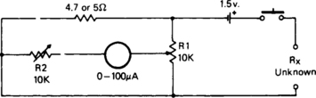
SIMPLE CONTINUITY TESTER FOR PCBs
This tester is for tracing wiring on PC boards. Resistors below 50 Ω act as a short circuit; above 100 Ω as an open circuit. The circuit is a simple multivibrator switched on by transistor T3. The components in the base of T3 are D1, R1, R2, and the test resistance. A 1.5-V supply, has insufficient voltage to turn on a semiconductor connected to the test terminals.
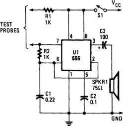
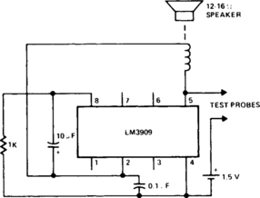
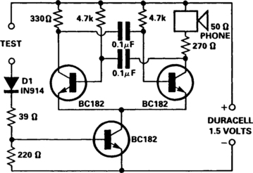
SIMPLE CONTINUITY TESTER
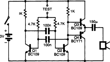
The pitch of the tone depends on the resistance under test. The tester will respond to resistance of hundreds of kilohms, yet it is possible to distinguish differences of just a few tens of ohms in low-resistance circuits. Q1 and Q2 form a multivibrator, the frequency of which is influenced by the resistance between the test points. The output stage (Q3 and Q4) will drive a small loudspeaker or an earphone.
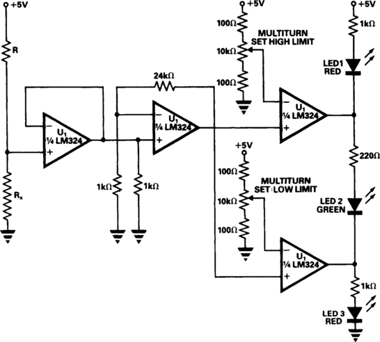
SINGLE-CHIP RESISTANCE CHECKER
A simple tester can be used for routine checks for resistance on production lines of relays, coils, or similar components, where frequent changes in resistance to be tested are not required. The tester is built around a single quad op amp chip, the LM324. R, which is chosen to be around 80 times the resistance to be checked, and the 5-V supply form the current source. The first op amp buffers the voltage generated across the resistance under test, Rx. The second op amp amplifies this voltage. The third and fourth op amps compare the amplified voltage with high and low limits. The high and low limits are set on multiturn presets with high and low limit resistors connected in place of Rx. LED 1 (red) lights when the resistance is high. LED 2 (green) shows that the resistance is within limits. LED 3 (red) indicates that the resistance is low.