Frequency-Measuring Circuits
The sources of the following circuits are contained in the Sources section, which begins on page 217. The figure number in the box of each circuit correlates to the source entry in the Sources section.
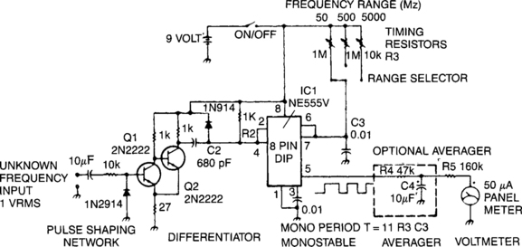
POWER-LINE FREQUENCY METER

The meter will indicate the frequency from a power generator. Incoming sine waves are converted to square waves by the 100 kΩ resistor and by the 6.8-V zener. The square wave is differentiated by the capacitor and the current is averaged by the diodes. The average current is almost exactly proportional to the frequency and can be read directly on a 100-mA meter. To calibrate, hook the circuit up to a 60Hz powerline and adjust the 5-KΩ pot to read 60mA.
AUDIO FREQUENCY METER
The meter uses time averaging to produce a direct current that is proportional to the frequency of the input signal.
INEXPENSIVE FREQUENCY COUNTER/TACHOMETER
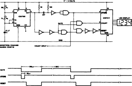
This circuit uses the low power ICM7555 (CMOS 555) to generate the gating, ![]() and
and ![]() signals. To provide the gating signal, the timer is configured as an astable multivibrator. The system is calibrated by using a 5-MΩ potentiometer for RA as a coarse control and a 1-kΩ potentiometer for RB as a fine control. CD40106Bs are used as a monostable multivibrator and reset time delay.
signals. To provide the gating signal, the timer is configured as an astable multivibrator. The system is calibrated by using a 5-MΩ potentiometer for RA as a coarse control and a 1-kΩ potentiometer for RB as a fine control. CD40106Bs are used as a monostable multivibrator and reset time delay.
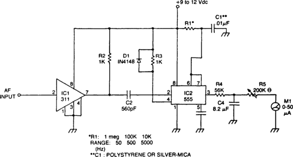
LINEAR FREQUENCY METER (AUDIO SPECTRUM)
The 555 is used in a monostable multivibrator circuit that puts out a fixed timewidth pulse, which is triggered by the unknown input frequency.
LOW-COST FREQUENCY INDICATOR

The circuit shows how two tone decoders set up with overlapping detection bands can be used for a go/no-go frequency meter. Unit 1 is set 6% above the desired sensing frequency and Unit 2 is set 6% below the desired frequency. Now, if the incoming frequency is within 13% of the desired frequency, either Unit 1 or Unit 2 will give an output. If both units are on, the incoming frequency is within 1% of the desired frequency. Three light bulbs and a transistor allow low-cost read-out. The IC is an EXAR 567.