Oscilloscope Circuits
The sources of the following circuits are contained in the Sources section, which begins on page 217. The figure number in the box of each circuit correlates to the source entry in the Sources section.
OSCILLOSCOPE CALIBRATOR
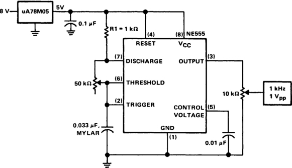
The calibrator can be used to check the accuracy of a time-base generator, as well as to calibrate the input level of amplifiers. The calibrator consists of an NE555 connected in the astable mode. The oscillator is set to exactly 1 kHz by adjusting potentiometer P1 while the output at pin 3 is being monitored against a known frequency standard or frequency counter. The output level, likewise, is monitored from potentiometer P2’s center arm to ground with a standard instrument. P2 is adjusted for 1 V pk-pk at the calibrator output terminal. During operation, the calibrator output terminal will produce a 1-kHz, square-wave signal at 1 V pk-pk with about 50% duty cycle. For long-term oscillator frequency stability, C1 should be a low-leakage mylar capacitor.
SCOPE SENSITIVITY AMPLIFIER
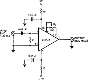
This circuit provides 20 ±0.1 dB voltage gain from 0.5 to 25 MHz and ± 3 dB from 70 kHz to 55 MHz. An LM733 video amplifier furnishes a low input-noise spec, 10-µV typical, measured over a 15.7-MHz bandwidth. The scale factor of the instrument can be preserved by using a trimmer R1 or a selected precision resistor, to set the circuit’s voltage gain to exactly 100.
SCOPE EXTENDER

The adapter allows four inputs to be displayed simultaneously on a single-trace scope. For low-frequency signals, less than 500 Hz, the adapter is used in the chop mode at a frequency of 50 kHz. The clock can be run faster, but switching glitches and the actual switching time of the DG201A limit the maximum frequency to 200 kHz. High frequencies are best viewed in the alternate mode, with a clock frequency of 200 Hz. When the clock is below 100 Hz, trace flicker becomes objectionable. One of the four inputs is used to trigger the horizontal trace of the scope.
EIGHT-CHANNEL VOLTAGE DISPLAY
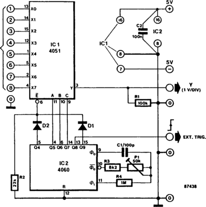
This circuit turns a common oscilloscope into a versatile eight-channel display for direct voltages. The trend of each of the eight input levels is readily observed, albeit that the attainable resolution is not very high.
The circuit diagram shows the use of an eight-channel analog multiplexer IC1, which is the electronic version of an eight-way rotary switch with contacts X0 through X7 and pole Y. The relevant channel is selected by applying a binary code to the A-B-C inputs. For example, binary code 011 (A-B-C) enables channel 7 (X6 Y). The A-B-C inputs of IC1 are driven from three successive outputs of binary counter IC2, which is set to oscillate at about 50 kHz with the aid of P1. Because the counter is not reset, the binary state of outputs Q5, Q6, and Q7 steps from 0 to 7 in a cyclic manner. Each of the direct voltages at input terminals 1 to 8 is therefore briefly connected to the Y input of the oscilloscope. All eight input levels can be seen simultaneously by setting the timebase of the scope, in accordance with the time it takes the counter to output states 0 through 7, on outputs Q5, Q6, and Q7.
The timebase on the scope should be set to 0.5 ms/div, and triggering should occur on the positive edge of the external signal. Set the vertical sensitivity to 1 V/div. The input range of this circuit is from −4 V to +4 V; connected channels are terminated in about 100 kΩ.
ANALOG MULTIPLEXER (CONVERTS SINGLE-TRACE SCOPE TO FOUR-TRACE)

This adapter circuit, based on a dual four-channel analog multiplexer, handles digital signals to at least 1 MHz, and analog signals at least through the audio range. The dual multiplexer’s upper half selects one input for display. The lower half generates a staircase to offset the baselines of each channel, keeping them separate on the screen. The emitter-follower buffers the staircase, which is then summed with the selected signal. A two-bit binary counter addresses the CMOS 4052 multiplexer.
OSCILLOSCOPE CONVERTER (PROVIDES FOUR-CHANNEL DISPLAYS)

The monolithic quad operational amplifier provides an inexpensive way to increase display capability of a standard oscilloscope. Binary inputs drive the IC op amp; a dual flip-flop divides the scope’s gate output to obtain channel-selection signals. All channels have centering controls for nulling offset voltage. A negative-going scope gate signal selects the next channel after each trace. The circuit operates out to 5 MHz.
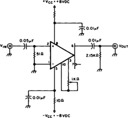
OSCILLOSCOPE/COUNTER PREAMPLIFIER

The circuit will provide a 20 ±0.1-dB voltage gain from 500 kHz to 50 MHz. The low-frequency response of the amplifier can be extended by increasing the value of the 0.05-µF capacitor connected in series with the input terminal. This circuit will yield an input-noise level of approximately 10 µV over a 15.7-MHz bandwidth. The gain can be calibrated by adjusting the potentiometer connected between pins 4 and 11. The 1-kΩ potentiometer can be adjusted for an exact voltage gain of 10. This preserves the scale factor of the instrument.
OSCILLOSCOPE-TRIGGERED SWEEP

The circuit’s input op amp triggers the timer, sets its flip-flop and cuts off its discharge transistor so that capacitor C can charge. When the capacitor’s voltage reaches the timer’s control voltage of 0.33 Vcc, the flip-flop resets and the transistor conducts, discharging the capacitor. Greater linearity can be achieved by substituting a constant-current source for frequency-adjust resistor R.

BEAM SPLITTER FOR OSCILLOSCOPE

The basis of the beam splitter is a 555 timer connected as an astable multivibrator. Signals at the two inputs are alternately displayed on the oscilloscope with a clear separation between them. The output is controlled by the tandem potentiometer RV1a/b, which also varies the amplitude of the traces.
ADD-ON SCOPE MULTIPLEXER
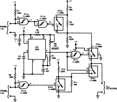
Fig. 14-11 Reprinted with permission of Radio-Electronics Magazine, October 1984. Copyright Gernsback Pulbications, Inc., 1984. Gernsback Pulbications, Inc.
The operation of the unit revolves around three ICs: a 4093 quad NAND Schmitt trigger, a 4066 quad analog switch, and a 7555 timer. When a high is fed to probe 1 in, it is inverted to IC1a and once again by IC1b so that the input to IC2a is high. That high causes the switch contacts in IC2a to close. With the contacts closed, a high-level output is presented to the input of IC2b. The high output is fed to probe 2 in. That signal is then inverted by IC1d and routed to IC2d, causing its contacts to open, and the unit to output a logic-level high. The output of IC2d is then fed to IC2c.
OSCILLOSCOPE PREAMPLIFIER
This circuit provides about 20-dB voltage gain with a frequency range from 0.5 to 50 MHz. You can extend the low-frequency response of this circuit by increasing the value of the 0.05-μF capacitor—or try removing the capacitor. This circuit delivers a particularly small level of input noise, measured at approximately 20 μV over a bandwidth range of 15 MHz.
Calibrate the gain by adjusting the gain potentiometer connected between pins 3 and 10, then adjust the 1-kΩ trimmer potentiometer for an exact voltage gain of 10; this helps preserve the scale factor of the oscilloscope.
FET DUAL-TRACE SCOPE SWITCH
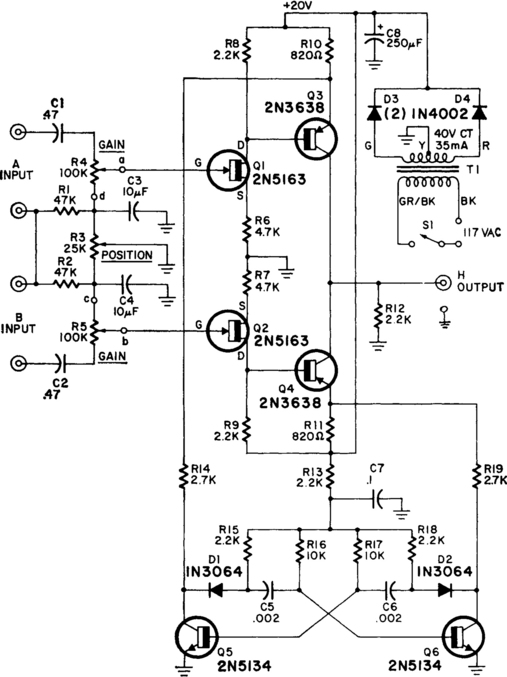
The switcher output goes to the single vertical input of the scope, and a sync line from one of the inputs is taken to the scope’s external-sync input. Frequency response of the input amplifiers is 300 kHz over the range of the gain controls. With the gain controls wide open so that no attenuation of the signal occurs, the frequency response is up to 1 MHz.
SCOPE CALIBRATOR
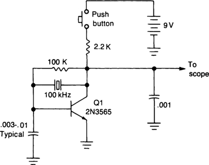
The calibrator operates on exactly 100 kHz, providing a reference for calibrating the variable time base oscillator of general-purpose scopes. For example, if the scope is set so that one cycle of the signal fills exactly 10 graticule divisions, then each division represents 1 MHz, or 1 µs. If the scope is adjusted for 10 cycles on 10 graticule divisions (1 cycle per division), then each division represents 100 kHz or 10 µs.
SCOPE CIRCLE DRAWER

The circuit is that of a quadrature sine and cosine oscillator. To generate circular displays, connect the two outputs to the X and Y inputs of the oscilloscope.
TRANSMITTER-OSCILLOSCOPE COUPLER FOR CB SIGNALS

To display an RF signal, connect L1 to the transmitter and points A and B to the vertical plates of the oscilloscope. Adjust L1 for minimum SWR and C3 for the desired trace height on the CRT. L2 = 4 turns #18 on ¾” slug tuned RF coil form, L1 = 3 turns #22 adjacent to grounded end of L2. C1, and C2 = 5pF, C3 = 75 pF trimmer.
CRO DOUBLER

IC1a, IC1b, and IC1c of the quad two-input NAND gate 4011 are connected as an astable multivibrator; IC1d is connected as an inverter. Terminals 3 and 11 of the 4011 produce square waves with opposite phases. The square waves, ep, at the output of IC1a, passing through differentiator C4R13, then form positive and negative pulses, et. The dual op amps of the LM358 are used as two gated amplifiers for singles e1 and e2 and fed through terminals 2 and 6, to be displayed simultaneously on the screen of the CRO.
The two opposite-phase square waves ![]() p and ep are used to gate IC2a and IC2b at terminals 3 and 5 of the LM358, respectively. Resistances R9 and R10 are preadjusted so that one op amp is driven to saturation while the other works normally as an amplifier. Thus, they will amplify signals e1 and e2 alternately, and two separate traces will be displayed on the screen. Resistance R12 can be varied to adjust the vertical separation of the two traces.
p and ep are used to gate IC2a and IC2b at terminals 3 and 5 of the LM358, respectively. Resistances R9 and R10 are preadjusted so that one op amp is driven to saturation while the other works normally as an amplifier. Thus, they will amplify signals e1 and e2 alternately, and two separate traces will be displayed on the screen. Resistance R12 can be varied to adjust the vertical separation of the two traces.
Select a suitable value for C1 with switch S, and adjust the pot of R1. The frequency of square waves can be varied from 1 to 106 Hz. This process is necessary to stablize the waveforms displayed on the screen. A common supply of 6 V is used in the circuit.
