Display Circuits
The sources of the following circuits are contained in the Sources section, which begins on page 217. The figure number in the box of each circuit correlates to the source entry in the Sources section.
VACUUM FLUORESCENT DISPLAY
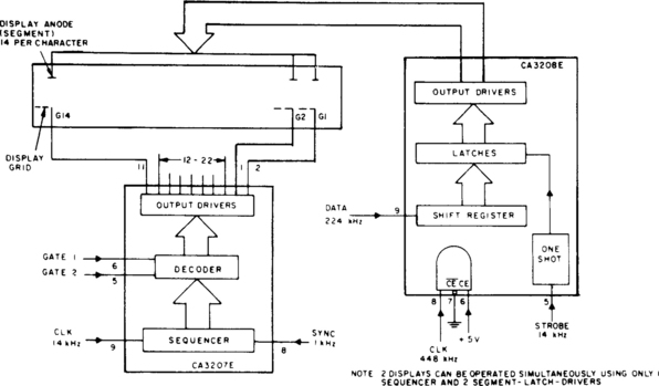
This circuit uses the CA3207 sequence driver and CA3208 segment latch-driver in combination to drive display devices of up to 14 segments with up to 14 characters of display. The CA3207 selects the digit or character to be displayed in sequence, CA3208 turns on the required alphanumeric segments.
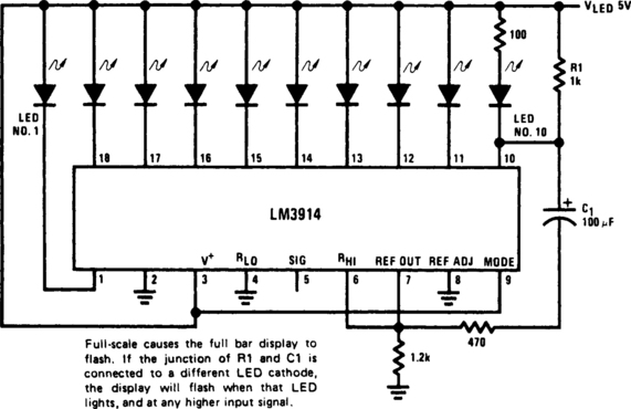
EXPANDED-SCALE METER

A bar-graph driver IC (LM314) drives an LED display. The LEDs might be separate or in a combined (integral) bar-graph display.

LED BAR PEAK METER DISPLAY
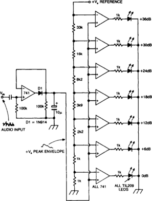
A bar column of LEDs is arranged so that as the audio signal level increases, more LEDs in the column light. The LEDs are arranged vertically in 6-dB steps. A fast response time and a 1 second decay time give an accurate response to transients and a low “flicker” decay characteristic. On each of the op amps inverting inputs is a dc reference voltage, which increases in 6-dB steps. All noninverting inputs are tied together and connected to the positive peak envelope of the audio signal. Thus, as this envelope exceeds a particular voltage reference, the op-amp output goes high and the LED lights. Also, all the LEDs below this are illuminated.
LED BRIGHTNESS CONTROL

This brightness of LED display is varied by using a photocell in place of one timing resistor in a 555 timer, and bypassing the other timing resistor to boost the timer’s maximum duty cycle. The result is a brighter display in sunlight and a fainter one in the dark.
10-MHz UNIVERSAL COUNTER

This is a minimum component complete Universal Counter. It can use input frequencies up to 10 MHz at input A and 2 MHz at input B. If the signal at input A has a very low duty cycle, it may be necessary to use a 74121 monostable multivibrator or similar circuit to stretch the input pulse width to be able to guarantee that it is at least 50 ns in duration.


LOW-COST BAR-GRAPH INDICATOR FOR ac SIGNALS

Indicator was designed to display the peak level of small ac signals from a variety of transducers including microphones, strain gauges, and photodiodes. The circuit responds to input signals contained within the audio frequency spectrum, i.e., 30 Hz to 20 kHz, although a reduced response extends up to 40 kHz. Maximum sensitivity, with VR1 fully clockwise, is 30 mV peak-to-peak. The indicator can be calibrated by setting VR1 when an appropriate input signal is applied.

LED-BAR/DOT-LEVEL METER

A simple level of power meter can be arranged to give a bar or dot display for a hi-fi system. Use green LEDs for 0 to 7; yellow for 8 and red for 9 to indicate peak power. The gain control is provided to enable calibration on the equipment with which the unit is used. Because the unit draws some 200 mA, a power supply is advisable instead of running the unit from batteries.
