Comparator Circuits
The sources of the following circuits are contained in the Sources section, which begins on page 217. The figure number in the box of each circuit correlates to the source entry in the Sources section.
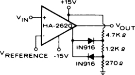
DIODE FEEDBACK COMPARATOR
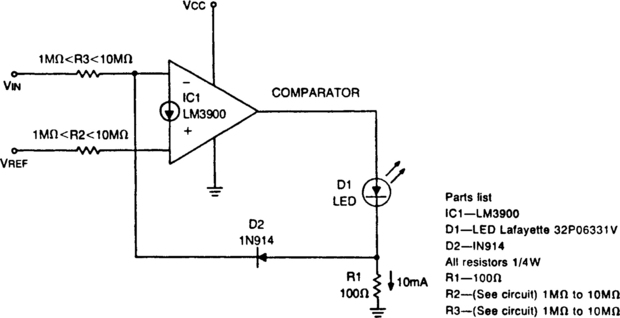
This circuit can drive an LED display with constant current independently of wide power-supply voltage changes. It can operate with a power supply range of at least 4 to 30 V. With 10 MΩ resistances for R2, R3, and the inverting input of the comparator grounded, the circuit becomes an LED driver with very high input impedance. The circuit can also be used in many other applications where a controllable constant-current source is needed.
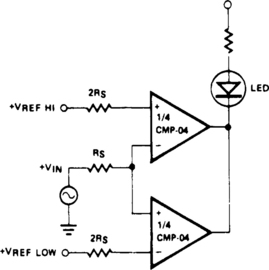
UNDERVOLTAGE/OVERVOLTAGE INDICATOR
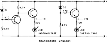
This circuit will make the appropriate LED glow if the monitored voltage goes below or above the value determined by zener diodes D1 and D2.
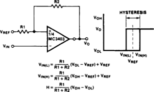
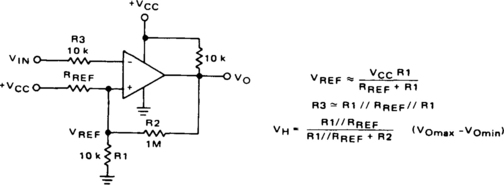
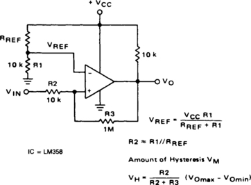
COMPARATOR WITH VARIABLE HYSTERESIS

An operational amplifier can be used as a convenient device for analog comparator applications that require two different trip points. The addition of a positive-feedback network introduces a precise variable hysteresis into the usual comparator switching action. Such feedback develops two comparator trip points that are centered about the initial trip point or reference point. The voltage difference, ΔV, between the trip points can be adjusted by varying resistor R2. When the output voltage is taken from the zener diode, as shown, it switches between zero and Vz, the zener voltage.


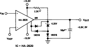
COMPARATOR WITH TIME OUT

The MC1422 is used as a comparator with the capability of timing output pulse when the inverting input (Pin 6) is ≥ the noninverting input (Pin 5). The frequency of the pulses for the values of R2 and C1 as shown is approximately 2.0 Hz, and the pulse width 0.3 ms.
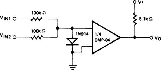
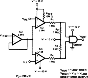
DUAL-LIMIT COMPARATOR

This circuit gives a positive output when the input voltage exceeds 8.5 V. Between these limits the output is negative. The positive limit point is determined by the ratio of R1, R2, and the negative point by R1 and R3. The forward voltage drop across the diodes must be allowed for. The output can be inverted by reversing the inputs to the op amp. The 709 is used without frequency compensation.