Signal-Injector Circuits
The sources of the following circuits are contained in the Sources section, which begins on page 217. The figure number in the box of each circuit correlates to the source entry in the Sources section.
SIGNAL INJECTOR I
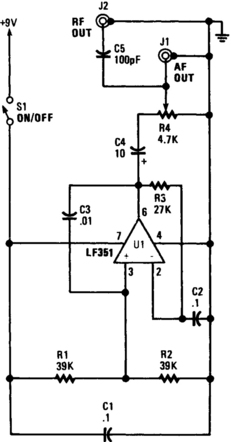
This unit is a single oscillator built around an LF351 JFET-input op amp. Resistors R1 and R2 bias the noninverting input, while R3 biases the inverting input from the output. This layout provides 100% negative feedback, but the decoupling caused by C2 gives reduced feedback and high-voltage gain when dealing with audio frequencies. The fundamental operating frequency is about 800 Hz. Potentiometer R4 is the output-level control. To use it start at the speaker. If no tone is heard, move back to the amplifier input, and listen for the tone. Still, if no tone is heard, continue backtracking from the output to the input, covering all stages in between. The stage where the signal is lost is the one that is not operating.
SIGNAL INJECTOR II

The unit provides a square-wave output that is rich in harmonic content. The circuit’s output frequency can be varied from 50 Hz to 15 kHz. The heart of the circuit is a 555 astable connected in its equal mark/space mode. The frequency is controlled by potentiometer R2 and capacitor C1. Resistor R3 controls the output level with the output ac-coupled through C3.