
Battery Monitoring Circuits
Voltage-Detector Relay for Battery Charger
Battery-Charge/Discharge Indicator
Precision Battery-Voltage Monitor for HTS
Undervoltage Indicator for Battery-Operated Equipment
Lithium Battery State-of-Charge Indicator
Step-Up Switching Regulator for 6-V Battery
Dynamic, Constant-Current Load for Fuel Cell/Battery Testing
The sources of the following circuits are contained in the Sources section, which begins on page 217. The figure number in the box of each circuit correlates to the source entry in the Sources section.
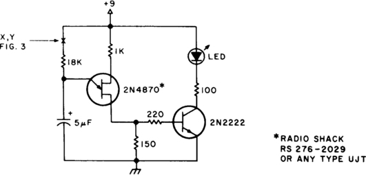
BATTERY STATUS INDICATOR
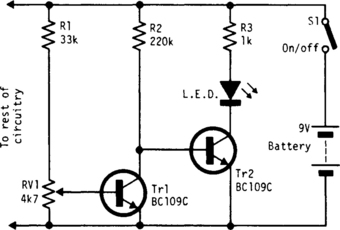
This indicator continually monitors the battery voltage during use and consumes only about 250 μA (until the end point is reached). Near the end point, Tr1 turns off, allowing Tr2 to illuminate the LED to increase current drain, which further leads to a distinct turn-off point.
LOW-BATTERY INDICATOR I

Under good battery conditions, the LED is off. As the battery voltage falls, the LED begins to flash until, in the low-battery condition, the LED lights continuously. Designed for a 9-V battery, with the values shown the LED flashes from 7.5 to 6.5 V.
LOW-BATTERY INDICATOR II
The indicator flashes an LED when the battery voltage drops below a certain threshold. The 2N4274 emitter-base junction serves as a zener, which establishes about 6 V on the L161’s positive input. As the battery drops, the L161 output goes high. This turns on the Darlington, which discharges C1 through the LED. The interval between flashes is roughly two seconds and gives a low-battery warning with only 10-μA average power drain.


VOLTAGE-DETECTOR RELAY FOR BATTERY CHARGER

While the battery is being charged, its voltage is measured at V. If the measured voltage is lower than the minimum, the relay will be energized, which will connect the charger circuit. When the battery voltage runs over the maximum set point, the relay is deenergized and it will be held that way until the voltage decreases below the minimum when it will be connected again. The voltage is lower than the threshold, VB (low breaking voltage); the relay will “assume” that such a low voltage is caused by one or several damaged battery components. Of course, VB is much lower than the minimum set point.
BATTERY-CHARGE/DISCHARGE INDICATOR

This circuit monitors car battery voltage. It provides an indication of nominal supply voltage as well as low or high voltage. RV1 and RV2 adjust the point at which the red/yellow and yellow/green LEDs are on or off. For example, the red LED comes on at 11 V, and the green LED at 12 V. The yellow LED is on between these values.
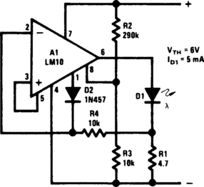
PRECISION BATTERY-VOLTAGE MONITOR FOR HTS

The precision voltage-monitor chip contains a temperature-compensated voltage reference. R1 divides down the battery voltage to match the built-in reference voltage of IC1 (1.15 V). When the voltage at pin 3 falls below 1.15 V, pin 4 supplies a constant current of 7 mA to drive a small LED. About 0.2 V of hysteresis is added with R2. Without hysteresis, the LED could flicker on and off when the monitored voltage varies around the set point, as might be the case on voice peaks during receive.
LOW-VOLTAGE MONITOR

This circuit monitors the voltage of a battery and warns the operator when the battery voltage is below a preset level by turning on an LED. The values are set for a 12-V automobile battery. The preset value is 10 V.
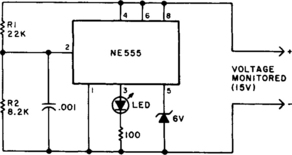
UNDERVOLTAGE INDICATOR FOR BATTERY-OPERATED EQUIPMENT
As a result of the low duty cycle of flashing LED, the average current drain is 1 mA or less. The NE555 will trigger the LED on when the monitored voltage falls to 12 V. The ratio of R1 to R2 only needs to be changed if you want to change the voltage point at which the LED is triggered.
BATTERY-CONDITION INDICATOR
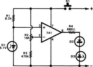
A 741 op amp is used as a voltage comparator. The noninverting input is connected to zener reference source. The reference voltage is 5.1 V. R2 is adjusted so that the voltage at the inverting input is half the supply voltage. When supply is higher than 10.2 V, the LED will not light. When the supply falls just fractionally below the 10.2-V level, the IC inverting input will be slightly negative of the noninverting input, and the output will swing fully positive. The LED will light and indicate that the supply voltage has fallen to the preset threshold level. The LED can be made to light at other voltages by adjusting R2.
EQUIPMENT-ON REMINDER
As a result of the low duty cycle of the flashing LED, the average current drain is 1 mA or less.
BATTERY-VOLTAGE MONITOR
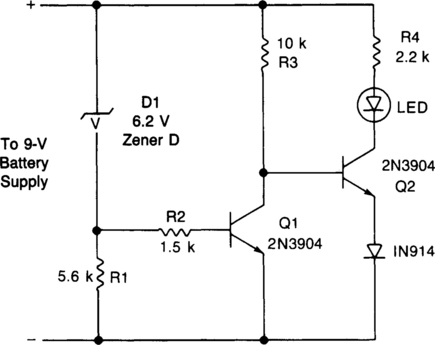
This circuit gives an early warning of the discharge of batteries. Zener diode D1 is chosen for the voltage below which an indication is required (9 V). Should the supply drop to below 7 V, D1 will cease conducting causing Q1 to shut off. Its collector voltage will now increase and cause Q2 to start conducting via LED1 and its limiting resistor R4.
BATTERY MONITOR

The circuit is quick and easy to put together and install, and tells you when battery voltage falls below the set limit as established by R1 (a 10,000-ohm potentiometer). It can indicate, via LED1, that the battery might be defective or in need of change if operating the starter causes the battery voltage to drop below the present limit.
LITHIUM BATTERY STATE-OF-CHARGE INDICATOR
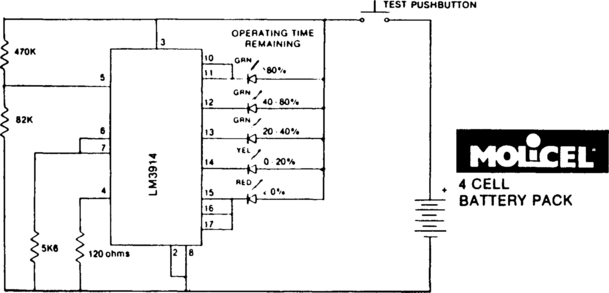
State-of-charge indication for a sloping-voltage discharge can be used as a state-of-charge indicator. A typical voltage comparator circuit that gives a visual indication of state-of-charge is shown. Components identified are for a 4-cell input voltage of 9.6 to 5.2 V.
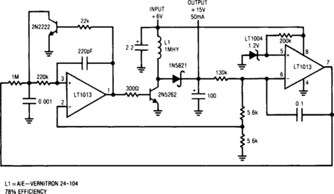
DYNAMIC, CONSTANT-CURRENT LOAD FOR FUEL CELL/BATTERY TESTING
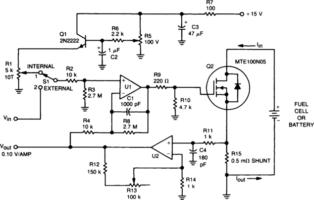
This circuit was designed for testing fuel cells, but it could also be used to test batteries under a constant-current load. It provides a dynamic, constant-current load, eliminating the need to manually adjust the load to maintain a constant load.
For fuel cell applications, the load must be able to absorb 20 to 40 A, and because a single cell develops only 0.5 to 1.0 V, bipolar power devices (such as a Darlington) are impractical. Therefore, this dynamic load was designed with a TMOS power FET (Q2).
With switch S1 in position 1, emitter-follower Q1 and R1 establish the current level for the load. In position 2, an external voltage can be applied to control the current level.
Operational amplifier U1 drives TMOS device Q1, which sets the load current seen by the fuel cell or battery. The voltage drop across R15, which is related to the load current, is then applied to U2, whose output is fed back to U1. Thus, if the voltage across R15 would tend to change, feedback to the minus input of U1 causes the voltage (and the load current) to remain constant. Adjustment of R13 controls the volts/amp of feedback. The Vout point is used to monitor the system.
CAR BATTERY-CONDITION CHECKER
This circuit uses an LED and a 4081 CMOS integrated circuit. The variable resistor sets the voltage at which the LED turns on. Set the control so that the LED lights when the voltage from the car’s ignition switch drops below 13.8 V. The LED normally will light every now and then for a short period of time. But, if it stays on for very long, your electrical system is in trouble.

