Light-Measuring Circuits
The sources of the following circuits are contained in the Sources section, which begins on page 217. The figure number in the box of each circuit correlates to the source entry in the Sources section.
LINEAR LIGHT-METER CIRCUIT
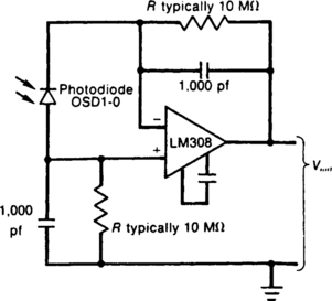
This circuit uses a low-input-bias op amp to give a steady dc indication of light level. To reduce circuit sensitivity to light, R1 can be reduced, but should not be less than 100 K. The capacitor values in the circuit are chosen to provide a time constant sufficient to filter high-frequency light variations that might arise, for example, from fluorescent lights.
LOGARITHMIC LIGHT-METER CIRCUIT
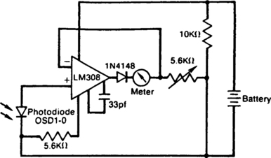
The meter reading is directly proportional to the logarithm of the input light power. The logarithmic circuit behavior arises from the nonlinear diode pn junction current/voltage relationship. The diode in the amplifier output prevents output voltage from becoming negative (thereby pegging the meter), which may happen at low lightlevels due to amplifier bias currents. R1 adjusts the meter full-scale deflection, enabling the meter to be calibrated.