
CHAPTER 33
Unwrapping UVs and Mapping Textures
Working with mapping modifiers
Applying decals with the UVW Map modifier
Using the Unwrap UVW modifier and the Edit UVW window
Creating seams
Using pelt mapping
Throughout the modeling chapter, as you created objects, the Generate Mapping Coordinates option appeared for almost all objects. Now you find out what mapping coordinates are and how to use them.
Mapping coordinates define how a texture map is aligned to an object. These coordinates are expressed using U, V, and W dimensions. U is a horizontal direction, V is a vertical direction, and W is depth.
When you enable the Generate Mapping Coordinates option for new objects, Max takes its best guess at where these coordinates should be located. For example, a Box primitive applies a texture map to each face. This works well in some cases, but you won't have to wait long until you'll want to change the coordinates.
Control over the mapping coordinates is accomplished using many different modifiers, including the granddaddy of them all—UVW Unwrap.
Peel and Pelt mapping are two additional mapping methods available within the Unwrap UVW modifier that let you stretch and smooth out mesh polygons onto a flat surface. You can access both from the Peel rollout.
Mapping Modifiers
Among the many modifiers found in the Modifiers menu are several that are specific to material maps. These modifiers are mainly found in the UV Coordinates submenu and are used to define the coordinates for positioning material maps. These modifiers include the UVW Map, UVW Mapping Add, UVW Mapping Clear, UVW XForm, MapScaler (WSM), Projection, Unwrap UVW, Camera Map (WSM), and Camera Map.
The Projection modifier is used to create normal maps and is covered in Chapter 34, “Creating Baked Textures and Normal Maps.”
UVW Map modifier
The UVW Map modifier lets you specify the mapping coordinates for an object. Primitives, Loft Objects, and NURBS can generate their own mapping coordinates, but you need to use this modifier to apply mapping coordinates to mesh objects and patches.
Note
Objects that create their own mapping coordinates apply them to Map Channel 1. If you apply the UVW Map modifier to Map Channel 1 of an object that already has mapping coordinates, then the applied coordinates overwrite the existing ones.
You can apply the UVW Map modifier to different map channels. Applying this modifier places a map gizmo on the object. You can move, scale, or rotate this gizmo. To transform a UVW Map gizmo, you must select it from the subobject list. Gizmos that are scaled smaller than the object can be tiled.
Many different types of mappings exist, and the parameter rollout for this modifier lets you select which one to use. The Length, Width, and Height values are the dimensions for the UVW Map gizmo. You can also set tiling values in all directions.
Note
It is better to adjust the tiling within the UVW Map modifier than in the Material Editor because changes in the Material Editor affect all objects that have that material applied, but changes to a modifier affect only the object.
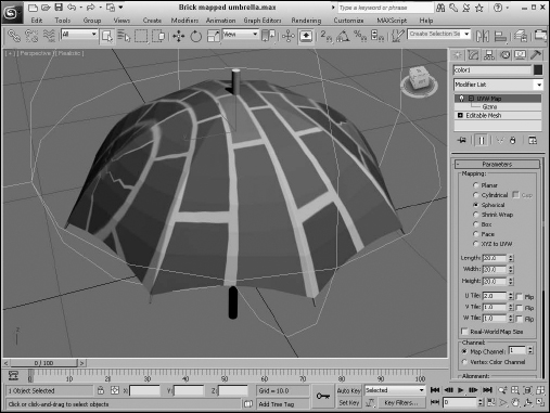
The Alignment section offers eight buttons for controlling the alignment of the gizmo. The Fit button fits the gizmo to the edges of the object. The Center button aligns the gizmo center with the object's center. The Bitmap Fit button opens a File dialog box where you can align the gizmo to the resolution of the selected bitmaps. The Normal Align button lets you drag on the surface of the object, and when you release the mouse button, the gizmo origin is aligned with the normal. The View Align button aligns the gizmo to match the current viewport. The Region Fit button lets you drag a region in the viewport and match the gizmo to this region. The Reset button moves the gizmo to its original location. The Acquire button aligns the gizmo with the same coordinates as another object.
Figure 33.1 displays a brick map applied to an umbrella using spherical mapping.
Tutorial: Using the UVW Map modifier to apply decals
After mapping coordinates have been applied either automatically or with the UVW Map modifier, you can use the UVW XForm modifier to move, rotate, and scale the mapping coordinates.
Most objects can automatically generate mapping coordinates—with the exception of meshes. For meshes, you need to use the UVW Map modifier. The UVW Map modifier includes seven different mapping options. Each mapping option wraps the map in a different way. The options include Planar, Cylindrical, Spherical, Shrink Wrap, Box, Face, and XYZ to UVW.
FIGURE 33.1 The UVW Map modifier lets you specify various mapping coordinates for material maps.
In this tutorial, you use the UVW Map modifier to apply a decal to a rocket model. Zygote Media created the rocket model.
To use the UVW Map modifier, follow these steps:
- Open the Nasa decal on rocket.max file from the Chap 33 directory on the CD.
This file includes a model of a rocket with the appropriate materials applied. The Chap 33 directory on the CD also includes a 300—600 image of the word NASA in black capital letters on a white background. The background color of this image was set to be transparent, and the image was saved as a .gif.
Note
The GIF format, typically used for Web pages, can easily make areas of the image transparent. These transparent areas become the alpha channel when loaded into Max.
- Open the Material Editor (or press the M key), and double-click on the Standard material in the Material/Map Browser. Name the material NASA Logo. Click the Diffuse color swatch, and select a white color. Then double-click on the Bitmap map button in the Material/Map Browser. Locate the NASA image from the Chap 33 directory on the CD, and click Open, then connect the Bitmap node to the Diffuse channel of the Standard material. The bitmap image loads, double-click the new node to view the Bitmap parameters display in the rollouts. In the Coordinates rollout, enter a value of –90 in the W Angle field. The letters rotate vertically. Then, in the Bitmap Parameters rollout, select the Image Alpha option.
- Select the lower white section of the rocket in the viewport, and open the Modify panel. At the top of the Modify panel, click the Modifier List and select the UVW Map modifier. Select the Cylindrical Mapping option, but don't select the Cap option in the Parameters rollout.
- With the cylinder section selected, open the Material Editor again, select the logo material, and click the Assign Material to Selection button or drag from the material's output socket to the rocket cylinder. To see the applied logo, make sure the Views
 Show Materials in Viewport As Shaded Materials with Maps or the Realistic Materials with Maps menus are enabled.
Tip
When a bitmap is applied to an object using the UVW Map modifier, you can change the length, width, and tiling of the bitmap by using the UVW Map manipulator. If you enable the Select and Manipulate button on the main toolbar, the manipulator appears as green lines. When you move the mouse over the top of these green lines, they turn red, and you can drag them to alter the map dimensions. Use the small green circles at the edges of the map to change the tiling values. As you use the manipulator, the map is updated in real time within the viewports if you have enabled the Show Map in Viewport option in the Material Editor.
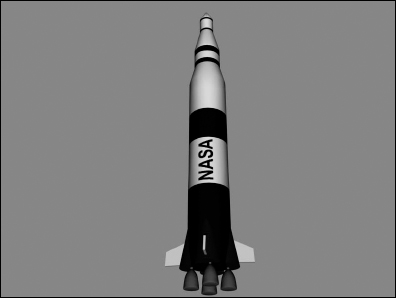
Figure 33.2 shows the resulting rendered image.
FIGURE 33.2 You can use the UVW Map modifier to apply decals to objects.
UVW Mapping Add and Clear modifiers
The UVW Mapping Add and the UVW Mapping Clear modifiers are added to the Modifier Stack when you add or clear a channel using the Channel Info utility. More on this utility is covered in Chapter 34, “Creating Baked Textures and Normal Maps.”
UVW XForm modifier
The UVW XForm modifier enables you to adjust mapping coordinates. It can be applied to mapping coordinates that are automatically created or to mapping coordinates created with the UVW Map modifier. The parameter rollout includes values for the UVW Tile and UVW Offsets. You can also select the Map Channel to use.
Map Scaler modifier
The Map Scaler modifier is available as both an Object-Space modifier and a World-Space modifier. The World-Space version of this modifier maintains the size of all maps applied to an object if the object itself is resized. The Object-Space version ties the map to the object, so the map scales along with the object. The Wrap Texture option wraps the texture around the object by placing it end to end until the whole object is covered.
Camera Map modifier
The Camera Map modifier creates planar mapping coordinates based on the camera's position. It comes in two flavors—one applied using Object-Space and another applied using World-Space.
The single parameter for this modifier is Pick Camera. To use this modifier, click the Pick Camera button and select a camera. The mapping coordinates are applied to the selected object.
Using the Unwrap UVW Modifier
The Unwrap UVW modifier lets you control how a map is applied to a subobject selection. It also can be used to unwrap the existing mapping coordinates of an object. You then can edit these coordinates as needed. This is accomplished by applying a texture map to an object. By selecting each face of the object, you then use the UVW Editor to move and orient the polygon in UVW space to determine how the polygon is set over the applied texture map. For example, imagine a bitmap texture that shows all the different sides of a die. In the UVW Editor, you could select and manipulate each face's UVs to align to the die sides included in the bitmap.
New Feature
The UVW Editor has been overhauled in 3ds Max 2012. Most of the common menu commands are now icon buttons, and several new features—such as the Peel toolset and the Grouping tools—are new.
You also can use the Unwrap UVW modifier to apply multiple planar maps to an object. You accomplish this task by creating planar maps for various sides of an object and then editing the mapping coordinates in the Edit UVWs interface.
Selecting UVW subobjects
The Unwrap UVW modifier lets you control precisely how a map is applied to an object. The Unwrap UVW modifier has Vertex, Edge, and Face subobject modes. In subobject mode, you can select a subobject, and the same selection is displayed in the Edit UVWs interface and vice versa. This synchronization between the Edit UVW window and the viewports helps to ensure that you're working on the same subobjects all the time.
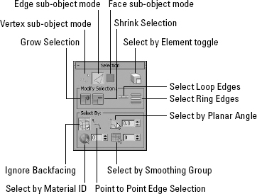
The Selection rollout, shown in Figure 33.3, includes a button with a plus sign and one with a minus sign. These buttons grow or shrink the current selected subobject selection. When Edge subobjects are selected, the Ring and Loop buttons and the Point-to-Point Edge Selection button become active. The Point-to-Point Edge Selection button is a great way to create seams. When you select two points, all the edges connecting those two points are selected.
In Face subobject mode, the Select by Material ID and Select by Smoothing Group buttons are active. The Select by Element button selects all the subobjects in the current element, which is an easier way to quickly select all subobjects of a defined element. You also can select to Ignore Backfacing and Select by Planar Angle.
FIGURE 33.3 The Selection panel for the UVW Unwrap modifier lets you work with Vertex, Edge, and Face subobjects.
The Select menu commands let you convert selections between vertices, edges, and faces. Additional options in the Select menu let you select all inverted and overlapped faces, allowing you to find potential problem areas.
Accessing the Edit UVWs interface
The Edit UVs rollout includes a button named Open UV Editor. This button opens the Edit UVWs interface. Within the UVW Editor, you have complete control over the various UVs, and the subobject selected in the viewport also is selected within the UVW Editor. The UVW Editor also can select and display the applied texture bitmap; the mapped bitmap also is shown in the viewport.
Tweaking vertices in the viewport
The Edit UVs rollout also includes a Tweak in View button. When this button is enabled, you can drag a single vertex in the viewports to move the texture mapping. This doesn't cause the vertex's actual position in the scene to move, only the mapping. The effects of this mode are apparent only in the viewport when the texture is visible. Texture maps can be made visible in the viewports using the Views ![]() Show Materials in Viewports As
Show Materials in Viewports As ![]() Shaded Materials with Maps or Realistic Materials with Maps.
Shaded Materials with Maps or Realistic Materials with Maps.
Using the Quick Planar Map
One of the easiest ways to isolate mapping surfaces is with the Quick Planar Map button found in the Edit UVs rollout under the Tweak in View button. If you select a set of faces either in the viewports or in the Edit UVW window and click this button, a planar map based on the X, Y, Z or an Averaged Normals is separated and the selected area is marked with a map seam. A button to Display Quick Planar Map shows the orientation of the mapping plan when enabled. Quick Planar Maps are one of the easiest ways to select, orient, and group mapping areas together.
Saving and loading mapping coordinates
You also can load and save the edited mapping coordinates using the Save and Load buttons in the Channel rollout, and the Reset UVWs button resets all the mapped coordinates. Saved mapping coordinate files have the .uvw extension and can be loaded for use on another object in another scene. For example, suppose you have a game level with multiple crates. If you create a texture that has all the different sides and correctly map the texture for one cube object, then all other crates in the scene could be correctly mapped by simply saving the mapping coordinates for the completed one and loading them into the others.
Each map can hold up to 99 mapping channels, and the Map Channel value lets you tell them apart. If a single object has multiple instances of the Unwrap UVW modifier applied, then each instance can have a different Map Channel value. Video game objects use these map channels to add wear and tear to a character as the game progresses. Also, the map channel can be a vertex color channel by enabling the Vertex Color Channel option.
The Configure rollout lets you set how the seams of the planar maps are displayed. The options include Map Seams, Peel Seams, and either Thick or Thin. Map seams show up as green lines, and peel seams show up as blue lines. By making the seams visible, you can easily tell where the textures don't match the object's creases.
Using the Edit UVWs Interface
Although several features for working with UVs are available in the various panels in the main interface, the main work is accomplished in the Edit UVWs interface. All changes made in the Edit UVWs window, shown in Figure 33.4, are automatically reflected in the viewports.
The Edit UVWs dialog box has multiple icons surrounding the main window. Along the top edge are buttons for selecting and transforming the selected subobjects. Table 33.1 shows and describes the buttons along the top edge.
FIGURE 33.4 The Edit UVWs interface lets you control how different planar maps line up with the model.
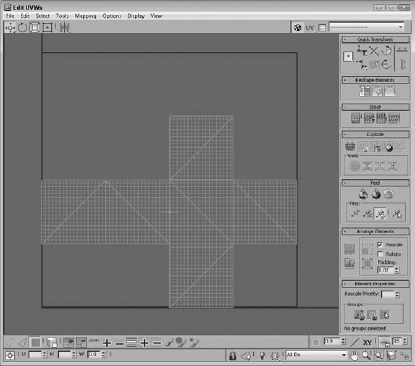
TABLE 33.1 Top Edit UVW Interface Buttons
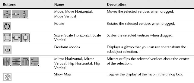
The gizmo is simply a rectangle gizmo that surrounds the current selection. Move the selection by clicking in the gizmo and dragging; Shift+dragging constrains the selection to move horizontally or vertically. The plus sign in the center marks the rotation and scale center point. Scale the selection by dragging one of its handles. Ctrl+dragging a handle maintains the aspect ratio of the selection. Click+dragging the middle handles rotates the selection. Ctrl+dragging snaps to 5-degree positions, and Alt+dragging snaps to 1-degree positions.
Within the Pick Texture drop-down list is a Checker Pattern option. This option applies a checker map to the mesh without having to assign a material. The checker pattern makes easy work of looking for stretching on the model. The drop-down list also includes any textures that are applied to the object. The selected texture appears in the background of the window.
Selecting subobjects within the dialog box
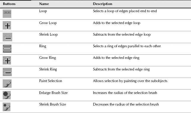
Under the main window in the Edit UVWs dialog box is a toolbar of icons for selecting different subobjects. Table 33.2 shows and describes these buttons.
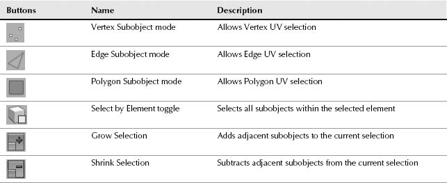
Within the Selection toolbar are the Selection modes with buttons for selecting Vertex, Edge, and Face subobjects. Selected subobjects in the Edit UVW interface are highlighted red. Using the + (plus) and – (minus) buttons, you can expand or contract the current selection. The paintbrush icon button is used to Paint Select subobjects, and the Expand and Shrink Brush buttons to its immediate right allow you to increase and decrease the brush size. The Select Element option selects all subobjects in the given cluster. This happens only when the Select Face subobject mode is enabled.
The Loop button automatically selects all edges that form a loop with the current selected edges. Edge loops are edges that run end to end. You also can use the Ring button to select adjacent edges that are parallel to each other. The Grow and Shrink buttons next to the Loop and Ring buttons are used to select the adjacent edges on either side of the current selection in the loop or ring direction.
Tip
The Loop and Ring buttons also can be used on vertices and faces if two or more are selected.
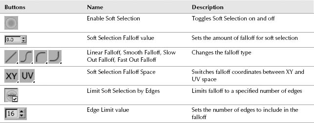
To the right of the selection buttons located under the main view in the Edit UVWs dialog box are several buttons for enabling and configuring soft selections. Table 33.3 shows and describes these buttons.
Using these controls, you can enable Soft Selection with a specified Falloff value. The UV and XY options let you switch between texture coordinates and object coordinates for the falloff. The Edge Distance lets you specify the Soft Selection falloff in terms of the number of edges from the selection instead of a falloff value. You also can choose the falloff profile as Smooth, Linear, Slow Out, or Fast Out.
TABLE 33.3 Soft Selection Buttons
Navigating the main view
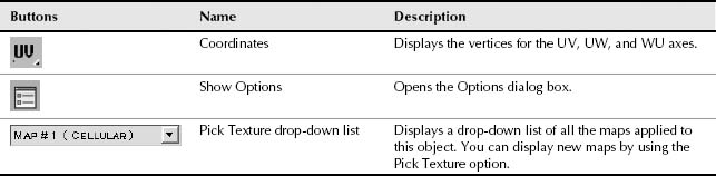
Along the bottom edge of the Edit UVWs dialog box are several more buttons for viewing the coordinate values, changing the display options and navigating the main view. Table 33.4 shows and describes these buttons.
TABLE 33.4 Lower Toolbar Buttons
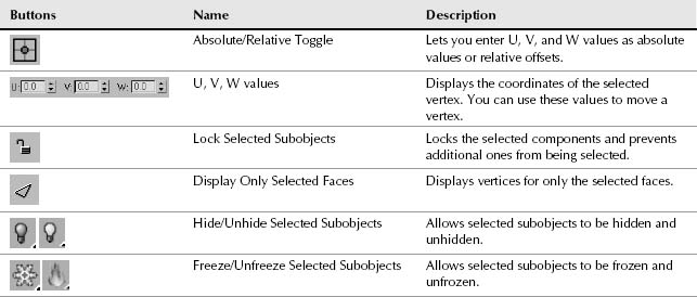
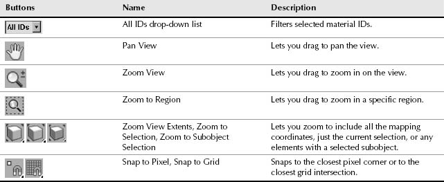
The buttons in the lower-right corner of the Edit UVWs dialog box work just like the Viewport Navigation buttons described in earlier chapters, including buttons to snap to grid and snap to pixel. You also can navigate about the Edit UVW window using the scroll wheel to zoom in and out of the window and dragging the scroll wheel to pan the view.
Using the Quick Transform buttons
One of the first tasks when unwrapping an object is to select and separate off different areas of polygons that have unique UVs. Each unique set of faces in the Edit UVW dialog box is called a cluster. For example, if you have a car with a matching texture, then the same texture can be mapped for each of the wheel hubs by placing each of the clusters for the wheel hub on top of each other over the bitmap section that shows the hub details. The same can be done for the side panels on the car, but one of the sides must be flipped horizontally. This is where the Quick Transform functions come in. They allow you to select and manipulate the different clusters.
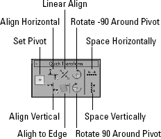
The Quick Transform rollout, shown in Figure 33.5, in the Edit UVWs dialog box includes buttons for aligning, rotating, and spacing subobjects.
The Set Pivot button includes options as flyouts to set the pivot at the center or at any of the four corners of the selection. You also can move the pivot to a precise location by dragging it when the Freeform Mode button on the top toolbar is selected. The pivot is marked by an orange set of crosshairs, and it is the point about which the selection is rotated and scaled.
The Align feature includes buttons to align the selected vertices or edges to the current pivot or to an average of the selected subobjects. The Align to Pivot option is the default, and the average align is available as a flyout. If you press and hold the Shift key, the entire edge loop is aligned. When used on an edge ring, all the individual edges are oriented to be perfectly parallel. The Linear Align button aligns the vertices or edges to a straight line that stretches between the two endpoints. The Align to Edge button is available only in Edge subobject mode. It rotates the entire cluster until the selected edge is either vertically or horizontally aligned.
FIGURE 33.5 The Quick Transform rollout includes buttons for aligning, rotating, and spacing subobjects.
Caution
The align features are to be used only on vertices and edges, but you can select and use them on faces. However, this only collapses the faces to a single line because it acts to align all vertices in the selection.
The Rotate +90 and Rotate –90 buttons rotate the selected subobjects 90 degrees in the Edit UVW interface. The rotation is about the set pivot. The Space Horizontal and Space Vertical buttons are used to equally space all the selected vertices or edges. The Shift key applies this to the entire edge loop.
New Feature
The Set Pivot, Align to Pivot, Linear Align, and Align to Edge buttons in the Quick Transform rollout of the Edit UVW dialog box are all new to 3ds Max 2012.
Straightening and Relaxing UV clusters
Within the Reshape Elements rollout are three buttons for reshaping the selected cluster of UVs. The Straighten Selection button is available only in Face subobject mode. It realigns the selected polygons into a rectangular grid with all polygons oriented vertically and horizontally.
If your mapping coordinates are too tight, and you're having a tough time moving them, you can use the Relax feature to space the vertices equally. The second button is Relax Until Flat. It causes all vertices within the cluster to move in order to remove any tension from the cluster. It also tries to make all faces in the cluster roughly the same size. Relaxing a cluster removes stretching that occurs across the surface of the area.
New Feature
The Straighten Selection and Relax Until Flat buttons in the Reshape rollout of the Edit UVW dialog box are new to 3ds Max 2012.
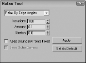
If the Relax Until Flat option pushes the cluster too far, the third button allows you to apply a custom set of relax settings. You can access the Relax Tool dialog box using the flyout button under the Relax:Custom button or using the Tools ![]() Relax menu command. This tool works like the Relax modifier, pushing close vertices away and pulling far vertices closer together. Selecting this menu option opens the Relax Tool dialog box, shown in Figure 33.6, which offers three relax methods: Relax by Face Angles, Relax by Edge Angles, and Relax by Centers. The Iterations value is the number of times to apply the relax algorithm. The Amount value is how aggressive the movements of the vertices are, and the Stretch value controls how much vertices are allowed to move. You also have options to Keep Boundary Points Fixed and Save Outer Corners.
Relax menu command. This tool works like the Relax modifier, pushing close vertices away and pulling far vertices closer together. Selecting this menu option opens the Relax Tool dialog box, shown in Figure 33.6, which offers three relax methods: Relax by Face Angles, Relax by Edge Angles, and Relax by Centers. The Iterations value is the number of times to apply the relax algorithm. The Amount value is how aggressive the movements of the vertices are, and the Stretch value controls how much vertices are allowed to move. You also have options to Keep Boundary Points Fixed and Save Outer Corners.
FIGURE 33.6 The Relax Tool dialog box includes custom settings for the Relax feature.
Stitching and welding
If you select some faces within the Edit UVWs dialog box and drag them away from the other faces, you notice that some edges connecting the selected faces with the non-selected faces remain. You can use the buttons in the Stitch and Explode rollouts, shown in Figure 33.7, to break these remaining edges and to stitch broken clusters back together again.
The Stitch button is used in Vertex mode to match the selected vertices along a border to their corresponding vertices. Clicking one of the Stitch buttons moves both faces to a new location, depending on the button you use. The Stitch to Target moves the selected subobjects to the location of their matching subobject. The Stitch to Average moves both to a location midway between each, and the Stitch to Source moves the matching subobjects to the location of the selected subobjects.
If you enable the Display ![]() Show Shared Sub-Objects menu command, the shared edges of the selected vertices are shown as blue lines. This indicates where the subobject face would be moved to when stitched.
Show Shared Sub-Objects menu command, the shared edges of the selected vertices are shown as blue lines. This indicates where the subobject face would be moved to when stitched.
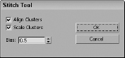
The Stitch Custom button moves the subobjects based on the Stitch Settings dialog box's configuration. You can access the Stitch Settings dialog box, shown in Figure 33.8, using the flyout button under the Stitch Custom button or using the Tools ![]() Stitch Selected menu command. The Stitch Tool dialog box includes options to align and scale the moved cluster, and the Bias value determines how close the selection moves to or away from the target subobject. A value of 0 moves the target to the source, and a value of 1 moves the source to the target.
Stitch Selected menu command. The Stitch Tool dialog box includes options to align and scale the moved cluster, and the Bias value determines how close the selection moves to or away from the target subobject. A value of 0 moves the target to the source, and a value of 1 moves the source to the target.
The Break button in the Explode rollout breaks the selected subobjects from their surrounding faces so they can be moved without stretching out the edges of the adjacent faces. This works best if the Break tool is used before moving the selected faces. When the Break tool is used on vertices or edges, two vertices or edges are created. This allows the independent vertices or edges to be moved away from each other. When Break is used on faces, a new cluster is created.
FIGURE 33.7 The Stitch and Explode rollouts include buttons for breaking, welding and stitching vertices.
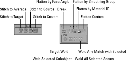
FIGURE 33.8 The Stitch Tool dialog box includes a Bias value to determine how far the selected subobjects move.
The opposite of Break is Weld, and the Explode rollout includes several ways to weld subobjects together. The Target Weld button enables a mode that lets you drag vertices or edges and drop them on their matching separated subobject. The cursor changes to a bold set of crosshairs when a matching subobject is under the cursor.
The Weld Selected Subobject button welds selected subobjects only if they are located within the Threshold value, which is found in the Unwrap Options dialog box. You can open the Unwrap Options dialog box using the Options ![]() Preferences menu command.
Preferences menu command.
If an edge is selected, its shared edge is highlighted in blue. Click the Weld All Selected Seams button once to automatically select the blue shared edges. If both shared edges are selected, then clicking the Weld All Selected Seams button again welds the two edges by moving both to an average location. The Weld Any Match with Selected button welds the selected subobject without requiring that both shared edges are selected, and it can be used on all vertices, edges, and faces.
The Edit menu also includes Copy, Paste, and Paste Weld commands. The Copy and Paste commands let you copy a mapping and paste it to another set of faces. The Paste Weld command welds vertices as it pastes the mapping.
Separating into clusters using flattening methods
The Explode rollout also includes several methods for automatically separating the object into clusters. This process is called flattening. The Flatten by Face Angle breaks the faces up using an angle threshold of 60 degrees. Any adjacent faces that have normals greater than this threshold are split along the edge they share. This breaks up a cube object into six separate faces.
You also can split up the UVs based on Smoothing Group values and Material IDs. Both of these are helpful if you've already applied smoothing groups or materials to the object. The Flatten Custom breaks the UVs into clusters based on the Flatten Mapping dialog box, which is accessed using the flyout button under the Flatten: Custom button or with the Mapping ![]() Flatten Mapping menu.
Flatten Mapping menu.
New Feature
The Flatten by Smoothing Group and the Weld Any Match with Selected buttons are both new to 3ds Max 2012.
The Flatten Mapping dialog box, shown in Figure 33.9, lets you break the mesh into clusters based on the angle between adjacent faces. This option is good for objects that have sharp angles like a robot or a machine. The Spacing value sets the distance between adjacent clusters.
FIGURE 33.9 The Flatten Mapping dialog box includes a Face Angle Threshold value for determining how clusters are separated.
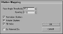
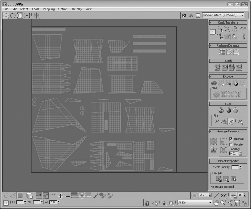
Figure 33.10 shows the UVs for a backhoe bucket that was separated into clusters using the Flatten Mapping method. All the clusters have been automatically aligned within the square texture area, and some smaller pieces have been placed within the holes created by the larger pieces. This makes the most of the available texture space.
In addition to the flattening options in the Explode rollout, the Mapping menu includes two additional auto-mapping options: Normal and Unfold Mapping.
The Normal Mapping option lets you select to map a mesh using only specific views, including Top/Bottom, Front/Back, Left/Right, Box, Box No Top, and Diamond. These views are based on the direction of the normals from the faces of the mesh. It is helpful for thin models like butterfly wings or coins.
FIGURE 33.10 The Flatten Mapping method was used to break this backhoe bucket object into several clusters.
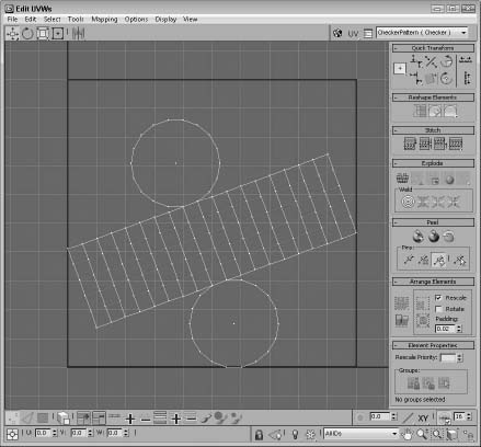
The Unfold Mapping option is unique because it starts at one face and slowly unwraps all the adjacent faces into a single segment if possible. Figure 33.11 shows a simple cylinder that has been unwrapped using this method. The advantage of this mapping is that it results in a map with no distortions. It includes two options: Walk to Closest Face and Walk to Farthest Face. You almost always want to use the Walk to Closest Face option.
Note
Within a single mesh, multiple different mapping methods can be used. For example, a car's wheel uses cylindrical mapping, but its hood might use planar mapping. Even a subobject selection can use different mapping methods.
FIGURE 33.11 The Unfold Mapping option splits the model and unfolds it by adjacent faces into a single segment.
Arranging and grouping clusters
Within the Edit UVW dialog box is a square area that represents the texture bitmap. The goal is to use as much of this texture space as possible to ensure that the maximum amount of detail from the texture is used on the model. The various buttons in the Arrange Elements rollout help with this task.
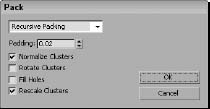
After all the various clusters are separated from each other, the Pack Custom button packs all the clusters to fit within the texture space using the settings in the Pack dialog box, shown in Figure 33.12. This dialog box is accessed using the flyout under the Pack Custom button or using the Tools ![]() Pack UVs menu command.
Pack UVs menu command.
The Pack UVs menu command lets you combine UVs into a smaller space. Packed UVs are easy to move and work with because they use a smaller resolution bitmap. Two packing algorithms are available in the Pack dialog box. The Linear Packing method is fast but not very efficient, and the Recursive Packing option is more efficient, although it takes longer. Within the Pack dialog box, the Spacing value sets the amount of space between each segment, and the Normalize Clusters option fits all clusters into the given space. The Rotate Clusters option allows segments to be rotated to fit better, and the Fill Holes option places smaller segments within open larger segments.
FIGURE 33.12 The Pack dialog box includes settings for crunching all clusters within the given texture space.
The Arrange Elements rollout also includes a Rescale Elements button that scales all clusters relative to each other. The Pack Together button fits all clusters within the texture space without normalizing. The Pack Normalize fits all clusters and allows scaling while fitting. You can select to enable or disable rescaling and rotating, and the padding value is the space between the clusters.
Within the Element Properties rollout are buttons to create, destroy, and select groups. For each group, you can set a Rescale Priority that determines which groups are rescaled during packing. To create a group of clusters, select two or more clusters using the Face subobject mode and click the Group Selected button. The Selected Groups label identifies each group with a number when selected.
New Feature
The ability to group clusters together is new to 3ds Max 2012.
Accessing the Unwrap Options
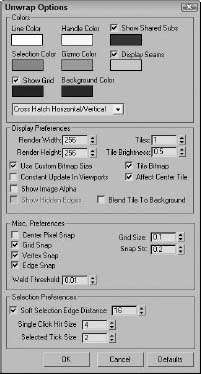
The Options ![]() Preferences menu command (Ctrl+O) opens the Unwrap Options dialog box, shown in Figure 33.13, and lets you set the Line and Selection Colors as well as the preferences for the Edit UVWs dialog box. You can load and tile background images at a specified map resolution or use the Use Custom Bitmap Size option. It also has a setting for the Weld Threshold and options to constantly update, show selected vertices in the viewport, and snap to the center pixel.
Preferences menu command (Ctrl+O) opens the Unwrap Options dialog box, shown in Figure 33.13, and lets you set the Line and Selection Colors as well as the preferences for the Edit UVWs dialog box. You can load and tile background images at a specified map resolution or use the Use Custom Bitmap Size option. It also has a setting for the Weld Threshold and options to constantly update, show selected vertices in the viewport, and snap to the center pixel.
The Bitmap Options section lets you specify the exact size of the loaded bitmap. This only affects how the bitmap is displayed in the interface and doesn't change the actual bitmap file dimensions. The Tile Bitmap option places the bitmap end to end for the specified number of tiles. The Constant Update option causes the viewport to update along with the texture map. The Show Hidden Edges option lets you make the hidden edges visible or invisible. The Center Pixel Snap causes the Pixel Snap button at the bottom right of the interface to snap to the center of the background pixels instead of to its edges.
Tutorial: Controlling the mapping of a covered wagon
The covered wagon model created by Viewpoint Datalabs is strong enough to carry the pioneers across the plains, but you can add a motivating slogan to the wagon using the Unwrap UVW modifier. In this tutorial, you add and edit the mapping coordinates for the covered wagon using the Unwrap UVW modifier.
FIGURE 33.13 In the Unwrap Options dialog box, you can set the preferences for the Edit UVWs dialog box.
To control how planar maps are applied to the side of a covered wagon, follow these steps:
- Open the Covered wagon.max file from the Chap 33 directory on the CD.
This file includes a covered wagon model. The Chap 33 directory also includes a 256×256 image, created in Photoshop, of the paint that you want to apply to its side. The file is saved as Oregon or bust.tif. (Note that the spelling in the image is rough.)
- With the covered section selected, choose Modifiers UV Coordinates Unwrap UVW. In the Parameters rollout, click the Edit button.
The Edit UVWs interface opens. In the Modifier Stack, select the Polygon subobject mode.
- In the Edit UVWs interface, choose Mapping Normal Mapping. In the Normal Mapping dialog box, select the Left/Right Mapping option from the drop-down list and click OK.
The left and right views of the wagon's top are displayed in the Edit UVWs interface.
- From the drop-down list at the top of the interface, select the Pick Texture option. The Material/Map Browser opens. Double-click on the Bitmap option, and select the Oregon or bust.tif image from the Chap 33 directory on the CD.
The texture appears in the window.
- Drag the mouse over all the faces for the lower half of the wagon's cover, and select the Tools Flip Horizontal menu command to flip the UVs so they match the top unselected UVs. Then drag and place the selected UVs on top of the unselected ones.
By matching these two UV sections together, you can apply the same texture to both sides of the covering.
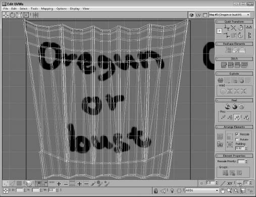
- Select all the UV faces, and with the Move tool, drag them to the center of the Edit UVWs window. Click and hold over the Scale tool, and select the Vertical Scale tool. Then drag in the window to vertically scale the vertices until they fit over the texture. Then horizontally scale the vertices slightly until the background texture is positioned within the wagon's top. When you're finished, click the X button in the upper-right corner to close the Edit UVW window.
Figure 33.14 shows the covered wagon with the mapped bitmap.
FIGURE 33.14 The Edit UVWs interface lets you transform the mapping coordinates by moving vertices.
- Open the Compact Material Editor. Click on the mapping button next to the Diffuse color, and double-click on the Bitmap type in the Material/Map Browser. Then select the Oregon or bust.tif file from the Chap 33 directory on the CD. Apply this material to the covered wagon top. Click the Show Map in Viewport button (the small checkerboard cube icon) to see the map on the covered wagon.
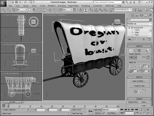
Figure 33.15 shows the results of the new mapping coordinates.
FIGURE 33.15 The position of the covered wagon's texture map has been set using the Unwrap UVW modifier.
Rendering UV templates
After all the UV coordinates are mapped onto a model, you can paint the desired textures in an external paint program like Photoshop and load the texture back into the Edit UVWs window, where they can be aligned to the correct UVs. Using the Tools ![]() Render UVs menu command, you can create a template that can be saved and loaded into Photoshop, showing you exactly where the UV boundaries are.
Render UVs menu command, you can create a template that can be saved and loaded into Photoshop, showing you exactly where the UV boundaries are.
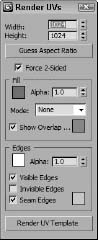
The Tools ![]() Render UVW Template menu command opens the Render UVs dialog box, shown in Figure 33.16. This dialog box lets you set the template's dimensions, set the template's Fill and Edges colors, and show overlaps and seams. The Fill mode can be set to None, Solid, Normals, and Shaded, providing more information about the object.
Render UVW Template menu command opens the Render UVs dialog box, shown in Figure 33.16. This dialog box lets you set the template's dimensions, set the template's Fill and Edges colors, and show overlaps and seams. The Fill mode can be set to None, Solid, Normals, and Shaded, providing more information about the object.
Clicking the Render UV Template button renders the template into the Render Frame Buffer window where it can be saved to the needed image format. Then within Photoshop, you can make the template layer a background layer that you can turn on and off to show the lines that you need to stay within when creating a texture.
FIGURE 33.16 The Render UVs dialog box lets you render and save a template for painting textures.
Mapping multiple objects
If your model is divided into several different pieces, you're in luck because Max allows you to apply the Unwrap UVW modifier to several pieces at once. When loaded into the Edit UVW window, the wireframe for each piece is displayed using its object color, which makes identifying the various separate pieces easy.
Tutorial: Creating a mapping for a fighter plane
As a final example of unwrapping, you add a Navy logo to a P-28 Trojan fighter plane. This plane was created by Viewpoint Datalabs. The logo was created and saved as a PNG file, which allowed the background to be saved as transparent. This allows the shiny metallic material to show through the applied logo.
For this tutorial, you add the logo to one of the wings. The tricky part of this tutorial, which you didn't have for the earlier rocket tutorial, is that the wing's ailerons are separated from the wing. This makes it possible to animate the ailerons.
Note
I realize that all you military aircraft enthusiasts out there know that the logo actually belongs on the fuselage and not on the wing, but the fuselage isn't divided into separate parts like the wing, so I'm taking creative license for the sake of the tutorial.
To add a texture map to several pieces of an airplane, follow these steps:
- Open the T-28 Trojan plane.max file from the Chap 33 directory on the CD.
- In the Perspective view, select the wing and the aileron and flaps. Don't select the molding between the wing and the ailerons.
- Select the Modifiers UV Coordinates Unwrap UVW menu to apply the modifier to all the selected pieces. Then click the Edit button in the Parameters rollout to open the Edit UVWs window.
- From the drop-down list at the top right of the Edit UVWs interface, select the Pick Texture option. The Material/Map Browser opens. In the Search by Name field, type Bitmap and double-click the Bitmap option, and select the T-28 Trojan logo.png image from the Chap 33 directory on the CD. To focus the bitmap, disable the Tile Bitmap option in the Options panel of the Edit UVWs window.
The texture appears in the window.
- Select Face subobject mode in the Modifier Stack and click in the viewport on the center of the right wing. Then click the Expand Selection button (the one with the plus sign) at the bottom of the Edit UVWs window to grow the selection. Keep clicking the Expand Selection button until the entire right half of the wing is selected. Then select the Tools Break command. Then zoom out in the Edit UVWs window, and move the separated wing to the top of the window so it doesn't overlap any other sections.
The selected wing UVs are separated from the rest of the wing object, which includes both wings.
Tip
Another way to select the faces is to use the Planar Angle value, which selects all the polygons on one side of the wing.
- Select the center of one of the right ailerons, and click the Expand Selection button until the entire part is selected. Then click the Planar button in the Projection rollout in the Command Panel to orient the part to match the wing. Then move the aileron up to the top of the Edit UVWs window near the wing UVs. Repeat this step for the other right aileron.
- Enable the Select Element option at the bottom of the Edit UVWs window so you can select the entire part by clicking it. Then use the Freeform mode button to move and scale the ailerons to fit next to the wing.
Tip
If you need to seamlessly fit two separate parts together, you can use the Welding feature in Vertex subobject mode to weld the vertices on each part.
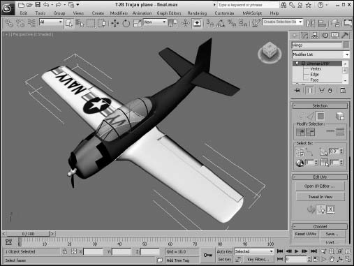
- Select all the remaining UVs, and move them to the bottom of the window where they don't overlap the logo. Then select the positioned wing and ailerons, and click the Rot −90 button to rotate the wing to align with the logo. Then scale and position the UVs over the logo, as shown in Figure 33.17. Then close the Edit UVWs window.
- Press the M key to open the Material Editor. Click the mapping button next to the Diffuse color, and double-click the Bitmap type in the Material/Map Browser. Then select the T-28 Trojan logo.png file from the Chap 33 directory on the CD. Apply this material to the selected wing and ailerons. Click the Show Map in Viewport button (the small checkerboard cube icon) to see the map on the plane.
FIGURE 33.17 The UVs are positioned to match the loaded bitmap.
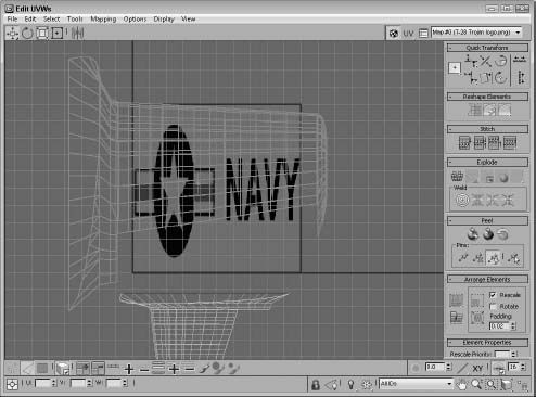
Figure 33.18 shows the results of the plane mapping. After the map is applied to the plane and visible in the viewports, you can open the Edit UVWs window again and tweak the mapping coordinates.
Using the Spline mapping
Spline mapping uses a spline and its cross sections to define the mapping coordinates. Tubular objects created with the Loft compound object or with the Sweep modifier are typically very difficult to correctly map given they don't fit in any of the existing mapping constructs. They can be unwrapped, but these objects usually have a lot of polygons, and this makes it difficult to unwrap or to pelt map.
The answer to this tricky object type is to use the Spline mapping method. With this mapping method, you can select to align the map to circular or planar cross sections. You can also add different cross sections if the lofted object uses different cross sections. Spline mapping is selected from the Wrap rollout in the Command Panel.
Tutorial: Spline mapping a snake
Spline mapping works well for objects like tentacles, arms, and ropes that have strong bends that cause mapping to be distorted. It also works well for simple snakes coiled and ready to strike.
FIGURE 33.18 The logo map is positioned on the wing and spreads over to the ailerons also, even though they are separate parts.
To add a texture map to a snake so it follows its length, follow these steps:
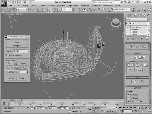
- Open the Snake.max file from the Chap 33 directory on the CD. This object was created using the Sweep modifier and includes a lot of polygons. Before converting to an Editable Poly and forming the head, I cloned the path used to create the snake, so a spline that runs along the snake's midline is also in the scene.
- With the snake objects selected, choose the Modifiers UV Coordinates Unwrap UVW menu to apply the modifier to the snake. Notice how the checkerboard texture is stretched along the snake's neck and head.
- In the Modify panel, select the Face subobject and drag over all the polygons in the viewport or use the Ctrl+A shortcut to select them all. Then click the Spline mapping button in the Wrap rollout. This opens a simple panel where you can choose the Pick Spline button. Then choose the midline spline in the viewport. Notice how the mapping is immediately updated and aligned to run along the length of the snake, as shown in Figure 33.19.
FIGURE 33.19 Spline mapping lets you align the mapped textures to follow the length of a selected spline.
Unfolding a loop strip
Another handy tool in the Wrap rollout is the Unfold Strip from Loop. This feature is enabled when Edge subobject mode is enabled and is best used with an edgeloop. Once an edgeloop is selected, clicking this button will separate the polygons adjacent to the selected edgeloop and stretch them out into a long straight set of rows, which makes it easy to paint a texture.
Note
When the Unfold Strip from Loop command is used, the scale of the strip will be made extra large. Use can use the Pack tool to fit the strip back in scale with the other UVs.
Figure 33.20 shows an edgeloop selected from the snake mesh in the previous example. Then with the Unfold Strip from Loop command, the polygons that run along the entire length of the snake have been pulled away as a separate strip.
FIGURE 33.20 Loop strips are easily separated from the rest of the mesh with the Unfold Strip from Loop button.
Using Peel and Pelt Mapping
In addition to the flatten, normal, and unfold mapping methods, the Unwrap UVW modifier includes nifty mapping methods for automatically unwrapping the UVs called Peel and Pelt mapping. But, before we dive into these methods, we need to understand and divide the mesh using seams. Seams are the borders between the various UV clusters. They can appear along smoothing groups, material boundaries, and hard edges.
Creating seams
Seams should be located in areas of the model that aren't clearly visible. For example, if you are unwrapping a head model, the back and top of the head are good choices because they probably will be covered with hair that will hide the seam. Locating a seam on the midline up the front of the face is a terrible choice, because lining up face details like the lips and the nose on opposite ends of the map is difficult. You also can define seam edges yourself using the buttons found in the bottom of the Peel rollout in the Command Panel.
Some seams are available when the Unwrap UVW modifier is first applied. These default seams follow the boundaries of the elements that make up the mesh. Seams are identified in the viewports as thick green lines. You can edit seams using the Edit Seams button in the Peel rollout. You also can create new seams using the Point to Point Seams and the Convert Edge Selections to Seams buttons.
Note
All open borders are automatically made into seams.
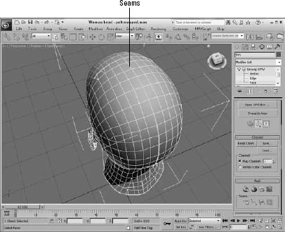
The Edit Seams button, at the bottom of the Peel rollout, lets you click edges to highlight them as seams. Press and hold the Alt key, and click an edge to remove it from the seam. This method can be time-consuming if you have a complex mesh. The Point to Point Seam button lets you click a starting point; a rubber band line then appears that lets you extend to an ending point. A seam is created between these two points using the shortest possible route. After an ending point is selected, the rubber band remains, letting you add to the seam. Right-click to exit the rubber band and to choose a new starting point. Figure 33.21 shows the seams added to the head model.
Tip
When placing pelt mapping seams, try to position the seams where they aren't readily visible, such as under the arms and legs or down the middle of the back.
FIGURE 33.21 Seams define where the mesh can be split.
The Convert Edge Selection to Seams button converts an existing edge selection to a pelt seam, and the Expand Face Selection to Seams button selects all faces that are next to the seams. This is an easy way to select all faces within a cluster.
The Configure rollout contains options to display Map and Peel Seams. If either of these options is enabled, the seams are clearly shown. You also can set the size of the seams to thin or thick.
Using the Peel tools
The Peel tools are a new method of unwrapping UVs based on the LSCM (Least Square Conformal Maps) algorithm. They provide a way to select and expand different areas of a cluster by pulling its vertices away from the center. The results are like stretching out some clay and having all the vertices stretch around the movement.
New Feature
The Peel tools are new to 3ds Max 2012.
It is best to define the seams to use before using the Peel tools, but you also can break, weld, and work with the cluster while toggling Peel mode on and off. After a cluster that you want to work with is selected using the Faces subobject mode, select all the faces in the cluster using the Expand Face Selection to Seams button in the Peel rollout of the main interface or by enabling the Select by Element toggle in the Edit UVW dialog box.
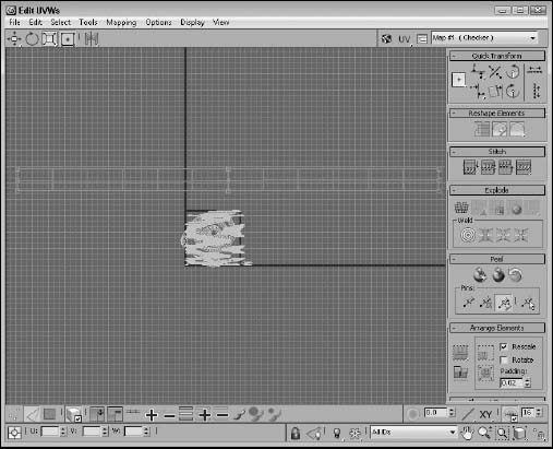
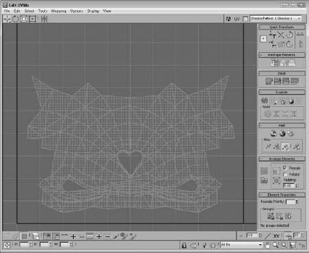
Then either click the Quick Peel Map button or enable the Peel mode button in the Peel rollout. The Quick Peel Map button makes its best guess and unwraps the cluster, but Peel mode lets you select and drag individual vertices around to spread out the cluster after you switch to Vertex subobject mode. Figure 33.22 shows the UVs of a lion toy's face after using the Quick Peel Map button.
FIGURE 33.22 The lion toy face cluster is displayed after using the Quick Peel Map.
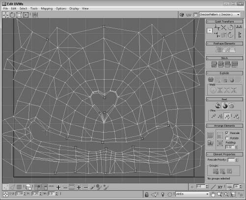
When the Quick Peel Map button gets fairly close, enable the Peel mode button, switch to the Vertex subobject mode, and then select and drag the vertices toward the top of the cluster away from the center to spread out the vertices. As you move each vertex, the rest of the cluster moves with it.
After the moved vertices are in place, you can pin them so they stay put. This allows the rest of the cluster to stretch out as other vertices are moved. Within the Peel rollout in the Edit UVWs window are several buttons for pinning the selected vertex, removing a pin, automatically pinning any moved vertices, and selecting all pinned vertices. Figure 33.23 shows the same cluster after pulling and pinning several vertices. Notice how the cluster makes much better use of the available texture space and how crowded areas have opened up.
FIGURE 33.23 The lion toy face cluster is displayed after moving and pinning vertices.
If you find that moving the vertices isn't helping, you can always click the Reset Peel button to start over. This automatically removes all pins and resets the cluster layout.
Using Pelt mapping
Pelts remind me of early turn-of-the-century explorers and trappers who captured and skinned critters such as foxes and wolves and preserved their fur pelts on a circular rack. These furs were valuable commodities that could be traded for whatever the trapper needed. The market for such furs has diminished significantly, but the concept works well for the virtual world as a mapping method for applying textures to 3D objects.
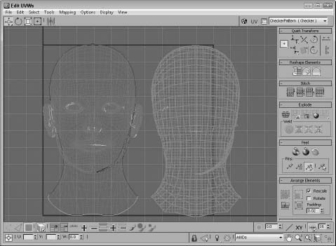
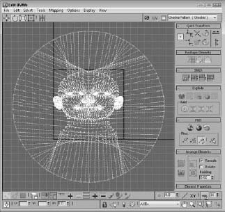
Another automatic mapping method available in the Peel rollout of the Command Panel is Pelt mapping. Consider mapping a complex mesh like the human head. Using traditional mapping methods, you would divide the head into sections based on planar projections like those in Figure 33.24. The UVs for this head include planar views of the front and back of the head. These provide good UV coordinates for features that are straight on with the projection, but the ears and the sides of the nose are all wrong using this method. You could divide the mesh into more projections, including one for each side of the head and for under the chin, but then you need to deal with matching the seams between the different parts, which is a tough challenge.
FIGURE 33.24 Planar mapping isn't a good solution for a complex head mesh.
Pelt mapping overcomes these difficulties by allowing the user to define the seams for the mesh. These seams can be located along material boundaries or along mesh borders. The vertices along these defined seams are then positioned around the edges of a circle called the Stretcher and pulled until the mesh UVs are pulled flat. This results in clearly displaying and flattening all the UVs for the selected part, allowing you to easily paint and apply a texture map.
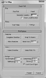
After the seams are defined, select all the faces that are to be mapped and click the Pelt button in the Peel rollout in the Command Panel. This opens the Edit UVW window along with the Pelt Map panel, shown in Figure 33.25.
FIGURE 33.25 The Pelt Map dialog box includes commands for stretching the pelt mapping.
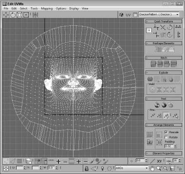
The Edit UVWs window opens with the front projection displayed, and all seam points are positioned in a circle around the selected faces, as shown in Figure 33.26. The circle of seam points is called the Stretcher, and the lines connecting the Stretcher points to the selected faces are springs.
FIGURE 33.26 Pelt mapping positions all seam points in a circle around the selected faces.
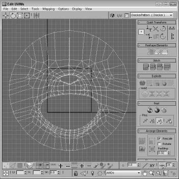
The Start Pelt button causes the springs to pull at the selected UV faces, causing them to stretch toward the Stretcher using the defined spring properties. The stretching continues until you click the Stop Pelt button. If you enable the Show Local Distortion option, all UVs that are severely distorted appear in red. Figure 33.27 shows the UV faces after being stretched.
FIGURE 33.27 After being stretched, the UV faces are lined up quite well.
In the Pelt Options rollout are settings for altering the stretcher locations. The Select Stretcher and Select Pelt UVs buttons let you select and manipulate both the selected faces and the Stretcher points. You also can straighten and mirror the stretcher or have the UVs snap to seams. The Snap to Seams button is especially helpful if you have an object like a hand that curves back in on itself. If you Snap to Seams before stretching, the stretcher assumes the shape of the seams.
If you get confused, the Reset Stretcher button returns the mapping to its starting positions. The Relax buttons can be used to further move the UVs to eliminate any tension in the mapping.
Tip
To create an efficient pelt map, you should rotate the stretcher so the spring distance is at a minimum.
Tutorial: Using pelt mapping
Pelt mapping is especially helpful on characters because they have irregular seams and surfaces. The Pelt mapping method works well for smoothing out character textures.
To use pelt mapping on a character's face, follow these steps:
- Open the Lion toy face.max file from the Chap 33 directory on the CD.
This file includes just the face of a lion toy model.
- With the face mesh selected, choose Modifiers UV Coordinates Unwrap UVW. Choose the Face subobject mode, and select all the face subobjects in the face mesh.
- In the Peel rollout, click the Pelt Map button.
A planar gizmo appears in the center of the viewport. Rotate and move the gizmo so it's parallel to the face mesh and in front of it (or press the Align Y button).
- The Edit UVWs dialog box appears with each seam positioned along the Stretcher. Select all the stretcher points with the Select Stretcher button and rotate the Stretcher points about 10 degrees clockwise so the pelt is stretched out straight. Then click the Start Pelt button until the face is stretched out, as shown in Figure 33.28.
FIGURE 33.28 Using pelt mapping, you can stretch the UVs for a mesh object.
Summary
I covered lots of ground in this chapter because there are lots of different maps. Learning to use these maps will make a big difference in the realism of your materials.
In this chapter, you learned about the following:
- Understanding the basics of mapping coordinates
- Using mapping modifiers
- Applying labels with the UVW Map modifier
- Controlling mapping coordinates with the Unwrap UVW modifier
- Rendering a UV template
- Editing seams
- Using the Peel and Pelt mapping methods
In the next chapter, you learn how to use the Render to Texture interface to bake textures into an object. Creating normal maps is also covered.