CHAPTER 12
TERRAINS
Many games take place exclusively inside buildings or structures, like tunnels. And many other games involve exclusive outdoor game play. Then there are some games that have a mix of each.
When your game has an outdoor component, you need to represent the terrain, which in game terms is the combination of the topography (hilliness, for example) and the surface (grass, gravel, sand, and so on). The topography is modeled using a 3D model, and the terrain surface appearance is represented by textures.
In addition to representing the ground, you also need to represent the sky, if you want to have interesting outdoor game play. Typically, a construct called a skybox is used to represent all of the sky, from horizon to horizon.
TERRAINS EXPLAINED
To understand terrains in a game development context, we need to look at the characteristics of the terrain we want to model. These characteristics will drive our need for the data that defines the terrain we want to make and therefore will heavily influence how and where we obtain that data.
Terrain Characteristics
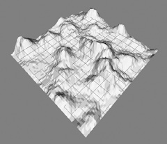
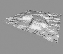
A basic unit of terrain is the tile. Essentially, a terrain tile is a collection of polygons that form a 3D model that represents the terrain, as depicted in Figure 12.1. Terrain tiles are also called terrain blocks, and this latter term is seeing more usage these days.
Figure 12.1
An untextured terrain tile.
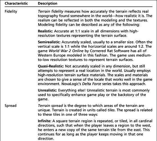
When we model terrain in a game, we have to make a number of choices. We need to decide the level of terrain fidelity we want to achieve. Another choice is to figure out the spread of the terrain. Finally, we need to decide what sort of freedom the terrain embodies. Table 12.1 lists these characteristics and the ramifications of each choice.
There are practical considerations that direct our terrain design choices. Many game engines simply aren’t capable of handling the distances involved in large-scale terrains or the number of objects required to appropriately populate them. Some game genres aren’t suited to open terrains—the player needs to be confined in order to advance the game story as required.
Terrain Data
When you want to create a high-fidelity terrain model of a real place in the world, you are going to need to get the data from somewhere. If the area in question is small enough, you may be able to go out and gather the information yourself if you’re handy with a theodolite (a surveyor’s tool). You might be able to glean the necessary information from topographic maps. In either case there is a lot of work involved in the data-gathering phase alone. You will need accurate distance measurements and altitudes, as well as photos of the terrain surface.
But don’t despair! There are sources for high-resolution terrain information available on the Internet. If you go to http://edcwww.cr.usgs.gov, the web portal for the United States Geological Survey’s research center (USGS; part of the U.S. government), you can find a wealth of terrain data.
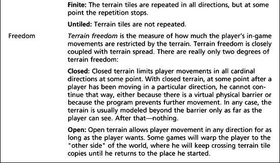
Table 12.1 Terrain Characteristics
The data is available in several forms, but the standard form is the Digital Elevation Model (DEM). DEM-formatted data files have the .dem file extension. Another format in use is the Digital Terrain Model (DTM), which uses the .dtm file extension. Finally, a powerful and complex format called Spatial Data Transfer Standard (SDTS) also exists but is not in wide use outside of scientific niches. SDTS files are denoted by the .ddf file extension.
In any event, the terrain surface information is not included in these various model formats, so you’ll need to gather that as well. Again, the USGS comes in handy with its satellite imagery—some of it taken down to a resolution of less than a meter per image pixel.
DEM files provide elevation information for specific coordinates of places on Earth. DEM files can be converted to a format used by game engines called a height map. We won’t go into detail about how to use DEM data for your game, but you can use several of the resources listed in the appendixes to locate the data and tools needed.
TERRAIN MODELING
There are basically two approaches that Torque 3D uses to model terrain in a 3D world. In both cases 3D polygon models represent terrains.
We can import terrain data from one of the formats described earlier, providing it has been converted into height map format, or we can directly build the terrain ourselves. For realistic terrains, we will want to use the former approach. If we intend to make it up as we go along, or are just working from rough sketches or mental images, we can use the latter direct approach.
Height Maps
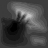
Figure 12.2 depicts a height map. As you can see, it’s a grayscale image. The 2D coordinates of the height map image map directly to surface coordinates in the game world. The brightness of each of the pixels in the image represents the altitude at that pixel’s location—the brighter the pixel, the higher the elevation. These examples use an 8-bit-per-pixel format, which means that 256 discrete elevations can be represented.
Figure 12.2
A terrain height map.

The concept is an elegant one and not difficult to grasp. If you are familiar with viewing topographic charts and maps, you’ll find that height maps have a familiar flavor to them, even though the contour lines are missing. One of the deficiencies of height maps is the resolution (as you can see in Figure 12.2). To represent a geographic locale that is 1 kilometer square, a height map that represents 1 square meter as a pixel needs 1,000 pixels per side, for a total of 1 million pixels—big, but not too large. If I want to increase the terrain area to cover 16 square kilometers (4 kilometers per side), then I need to store 16 million pixels. At 8 bits (or one byte) per pixel, that equals about 16MB of data. If we want to model the terrain for an area that is 10 kilometers per side, we are looking at almost 100MB of storage!
We can, of course, reduce the terrain resolution—let’s say, have a pixel equal 4 square meters in the game world. This would chop those 100MB back to 6.25MB. However, that gain is offset by the fact that our terrain will now be blockier and less realistic.
Going the other way, if we want that same pixel to represent half of a square meter, doubling the “resolution,” then that same 100MB of storage will only represent a terrain area of four square kilometers, one-quarter of the 16 square klicks we were just looking at! That’s right, I said “klicks” ! I grew up partly in Europe, and that’s how we always said “kilometers,” back in the day—too long ago for you to worry about.
Anyway, back on topic, Figure 12.3 shows a terrain model generated from the height map shown in Figure 12.2. In this case MilkShape 3D was used to import the height map and create the terrain object.
Figure 12.3
A terrain created from a height map.
Terrain Surface
In the simplest sense, terrain surface refers to all the stuff that you find on the ground, including:
![]() grass
grass
![]() flowers
flowers
![]() dirt
dirt
![]() pebbles
pebbles
![]() rocks
rocks
![]() trash
trash
![]() litter
litter
![]() pavement
pavement
![]() concrete
concrete
![]() moss
moss
![]() sand
sand
![]() stone
stone
Obviously this is not a comprehensive list, but it does demonstrate the point. These features drive the appearance of the terrain surface, and can obviously be represented by textures and bump and detail maps. But the representation does have its limits.
It’s important to not confuse the terrain surface with ground cover. There is a paucity of terms available to describe what terrain looks like in a broad sense as well as in a close-in sense.
In earlier editions of this book, the term “ground cover” was used to categorize those things I now call “terrain surface.” However Torque co-opted my use of that term with their new Torque 3D feature called Ground Cover available in the World Editor Library, in the Level Environment section that is used to add 3D-ish things like tufts of grass, small rocks, paper, etc., that protrude above the level of the terrain surface. Combined with judicious and careful application of terrain surface materials, you can make extremely realistic-appearing terrain.
We represent the terrain surface with textures. Our options for creating these textures are much like those we considered when we created textures for structures in Chapter 11—and the factors that dictate which way to choose are also similar. It boils down to the terrain characteristics in the game that matter to you.
We can also mix terrain surface materials in adjacent areas to portray a particular locale. It’s a good idea to develop your own library of generic terrain surface materials for use in various situations.
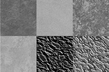
Figure 12.4 illustrates some of the possible varieties of terrain surface materials. From left to right in the top row you can see grass, sand, and an intermixed sand and grass texture. In the bottom row from left to right is dirt, a muddy track, and eroded wet sand.
Figure 12.4
Some example terrain textures.
Tiling
Unless you are going to create specific terrain surface materials for every square inch of terrain (not impossible), you will end up tiling your terrain surface at some point. All the issues brought up with tiling in other contexts apply here, such as matching texture edges to get seamless transitions and ensuring lighting in the textures is both appropriate and uniform. Additionally, you should ensure that there are no patterns or marks in the texture that will stand out too much when the texture is repeated.
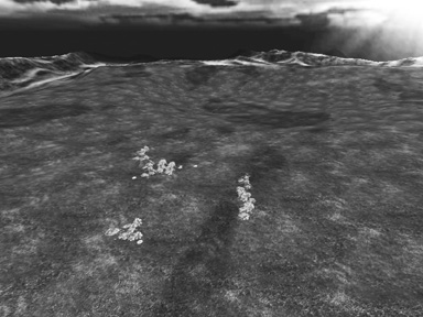
In Figure 12.5 you can see a repeating light pattern that tends to overpower the otherwise pleasing pastoral scene. (Okay, okay, it would be pastoral if a storm wasn’t brewing beyond the, um… Mountains of Pure Evil in the distance. But besides that….)
The culprit in this case is the grass texture used, which is shown in Figure 12.6.
Figure 12.5
A terrain with tiling artifacts.
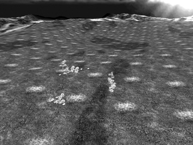
Figure 12.6
A texture with an undesirable feature.
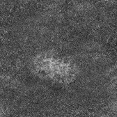
Notice the area of lighter grass, which is quite noticeably different from the rest of the image. When repeated over and over across large swaths of terrain, that feature detracts from the intended overall effect. We can enhance the image to minimize the problem, perhaps with something like that shown in Figure 12.7.
Figure 12.7
A texture without the undesirable feature.
The result is dramatic and the difference is quite obvious, as you can see in Figure 12.8. Now I confess that the texture could be better, but you have to admit that it is light-years ahead of the first version, shown in Figures 12.5 and 12.6.
Figure 12.8
The terrain with improved tiled texture.
CREATING TERRAINS
Okay, enough talk. Time for some action—let’s create some terrain. We’ll use the Torque 3D engine’s height map method using the in-game World Editor. There is another method, direct manipulation using the Terrain Editor, which we’ll use later in Chapter 18.
The Height Map Method
For this section, you will need to fire up Gimp. You should be fairly familiar with the basics by now, so I won’t hold your hand too much with respect to Gimp operations.
Note
Torque has traditionally used an in-game unit for length called a world unit (WU).
One WU in Torque 3D is equal to one unit in most third-party map editors. A WU is equivalent to one scaled meter (1 WU = 1 meter). You would not cause yourself psychological scarring if you used “meter” and WU interchangeably. After all, I do it, and I’m still perfectly norbal after years of interchanging.
1. Start with a drawing of the contours to create the height map image. If you have a source for colored contour drawings for a section of land drawn at full scale (1:1), such as shown in Figure 12.9, get one that suits your needs. If not, you can use the images shown here, but in their colored format, which you will find at 3D3ERESOURCESCH12. Use the files contour1.jpg and contour2.jpg as applicable.
2. Clip out the portion you want, and save it as a PNG image, as shown in Figure 12.10.
Figure 12.10
Cropped and resized contour map.
3. Now you need to do a little noodling over scale and unit numbers. As mentioned elsewhere, the terrain squareSize property in a Torque 3D mission file equals 1 by default. The terrain we are going to make will have 256 of these squares per side. I’ve chosen this number because this makes a tidy match with the number of pixels on a side of the images we will be working with.
4. Resize your image to 256 pixels by 256 pixels, if necessary. Set the X and Y resolutions in Gimp to 72 pixels/in. by choosing Image, Scale Image, and adjusting the X and Y Resolution values.
Caution
You must ensure that the dots-per-inch (DPI) or pixels-per-inch (PPI) setting for the image is a known value. I use 72 DPI. It’s important because later on you are going to use an opacity map. The resolution and the DPI of the opacity map must be the same as the height map you use.
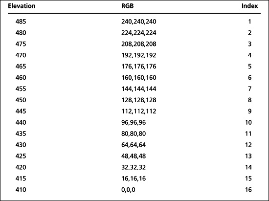
5. Save the image as a PNG file to preserve the original colors for the contours. In a moment you will paint over this contour image using gray color values representing the heights of the contour lines. In this case the contours range from an elevation of 410 feet to 485 feet. This information is available from the source of the contour maps. The grayscale can be any sequence of gray RGB values within the 256 colors ranging from 0,0,0 (black) to 255,255,255 (white).
6. Establish your scale keeping in mind that it’s best to have some separation between the indexed values so they can be easily seen as you paint the contours.
Examination reveals that there are 16 discrete elevations in the contour range of 410 to 485. Divide the 256 colors for the grayscale range by 16, and you will get the values in Table 12.2, which starts at the color (0,0,0) and works up.
Now that we have the values, we need to create what is commonly called an indexed color palette. We need to make a different color entry for each index.
7. With your candidate contour image file open, make sure it is configured to use an indexed color palette by choosing Image, Mode, Indexed. In the dialog box that comes up, just make sure that the Generate optimum palette radio button is checked, that the maximum number of colors is set to 256, and that Color dithering is set to None.
8. Click Convert to close the dialog box.
9. Choose Windows, Dockable Dialogs, Palettes to get the Palettes dialog box up.
Table 12.2 Elevation RGB Values
10. In the Palettes dialog box, click the New palette button, which is the second button from the left at the bottom of the dialog box. This brings up the Palette Editor.
11. Give your new palette a name by typing it in the edit box at the top of the Palette Editor dialog box.
12. Click the Save button, the first button on the left at the bottom of the Palette Editor. It’s a good idea to click this button after you create each new entry, just in case.
Now, for the next little while we will be working in the Palette Editor. To start out, we will create a new entry for our first index.
1. Open the Palette Editor menu by clicking the menu button—that’s the leftward-pointing arrow at the upper-right corner of the Palette Editor, to the left of the Close button (the little x).
2. Choose Palette Editor Menu, New Color from FG. It doesn’t matter what color the FG (Foreground Color) is at the moment, as long as it contrasts with black. We just want to create a new entry. After doing this, you will see a long thin horizontal rectangle filled with black. This is where our colors will be displayed for each index.
Also notice back in the Palettes window the new entry at the top with the name that you gave the new entry in the previous procedure. In the upper-left corner is a small square. This square bears the color that has been assigned from the Palette Editor. At the moment there is only one and it has been assigned the default color.
3. Click on the far left end of the rectangle and you will see a small square appear. If it is not at the very end of the rectangle, try again until you see the outline of a square at the extreme left end of the rectangle. This smaller rectangle is your first index.
4. Click the first index, and drag and drop it immediately to the right of its position. Another copy of the color will be deposited in the new spot. Keep doing this until you have 16 copies. By happy coincidence, this is exactly how many color entries will fit in that line. If you had made more than 16 copies, then a new line of entries would have been started. But you only need 16, so if you have too many entries, select one, and then click the trash can icon at the bottom to delete it (or right-click it, and select Delete Color).
5. Click the first entry (far left), and click the Edit Color button (third from left at bottom) or right-click the entry and choose Edit Color from the pop-up menu. You will get the (by now) familiar Color dialog box, this time called the Edit Palette Color dialog box.
6. Enter the RGB (240,240,240) values from Table 12.2 for index 1 into the appropriate edit boxes in the dialog box, and then click OK.
7. Repeat steps 1, 2, 3, and 4 for each of the other 15 indices in the table and then save your new palette.
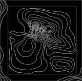
8. Now fill in your image following the contour lines as shown in Figure 12.11. Use a combination of the Brush and Fill tools, at your discretion, to complete the task.
Notice that in Figure 12.11 the grayscale value is the same at all the edges. This is because we want the edges to match when the terrain repeats itself, if it is tiled—and in this case that’s what we will be dealing with. The edges could be different values; you would then just match them at the top and bottom or left and right sides.
Figure 12.11
Contour map with grayscale values.
You can select the new palette we created by choosing the paint brush in the Toolbox and then clicking the foreground color. In the Change Foreground Color dialog choose the button on the right of the palette display. Then in the Palettes dialog, choose a palette and you’ll see the color selections available change depending on which palette you have chosen. We want to choose a color bar in the new grayscaled palette we’ve just created and then click OK.
9. When you have finished the “paint-by-number” process, convert the image to grayscale by choosing Image, Mode, Grayscale.
10. Save your image as a PNG file. I suggest myHeightmap256.png for the filename—you can use whatever name you like, just make sure you can remember the name, or at least recognize it as yours when you trip over it later when browsing for it.
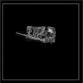
11. Flip the image around its X-axis—this flips the top with the bottom—by choosing Image, Transform, Flip Vertically. You should get an image like that in Figure 12.12. Make sure you save your work.
Notice the terrace effect in Figure 12.12. If you import this into Torque as is, you will have a set of terraced, or stepped, surfaces. If this is what you want, then you’re good to go. However, let’s go a bit further.
12. Make a copy of the image you just created and continue working now with the copy.
13. Select the entire image.
Figure 12.12
Terraced height map.

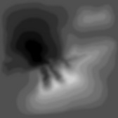
14. Choose Filters, Blur, Gaussian Blur to smooth out the edges a bit. Use a radius of about 7 for both horizontal and vertical, and then save your changes to this new image as a PNG file. You should get an image much like the one shown in Figure 12.13.
Figure 12.13
Blurred height map.
15. You don’t need to convert the image back to indexed mode after blurring, because Torque will do the interpolation for you when you import the image to create the terrain.
It can be more difficult to locate your original contour features after smoothing with Gaussian Blur. A quick work-around is to try reducing the radius or use the original image unblurred and smooth the terrain in Torque using the Terrain Editor (covered later).
A more time-consuming technique (but much more accurate and rewarding) is to create the terrain image at a much larger scale and reduce it to 256 by 256. For example, you might try constructing the image at around 2,048 by 2,048 or 4,096 by 4,096; this means much more painting time, but after reducing the image size again, the blending information is retained (although somewhat smoothed) by the resize algorithms. The resulting terrain is much more accurate than the Gaussian Blur process.
This last height map image is the one you will work with to create the terrain. Next, we will import this image into Torque 3D, using it to build a terrain block.
Note
For this chapter, as I’ve also indicated elsewhere, your Torque 3D root folder will be 3D3EDEMOExamples FPS Examplegame. All of the folders you will use, unless otherwise noted, will be inside that path.
16. Save your new heightmap image as art errainsmyHeightmapsmyHeightmap.png. If the art errainsmyHeightmaps folder does not already exist, create it.
17. Open the FPS Example, Blank Room with the World Editor button in the Torque Toolbox.
18. Look through your Scene tree (right-hand side, under the Scene tab), and if you have an object called GroundPlane, click on it, then press the Delete key to remove it.
19. Switch to the world camera, or what used to be called camera-fly mode, by pressing Alt-C to switch from player camera to world camera.
Tip
When you are in the game, but not in the World Editor, you can change to the world camera from the player camera by pressing F7. Once in world camera, you can fly anywhere you like, then spawn your player at the camera’s location by pressing F7—this also switches your view to the player camera. You can switch back and forth between the two cameras using Alt-C as a toggle.
HOWEVER, when you are in the World Editor, although the Alt-C command to toggle between the modes is unchanged, the player and world cameras are invoked with different key commands. Use Control-Q to switch to the world camera and Control-W to spawn the player at the camera, while switching to the player camera.
20. Choose File, Import Terrain Heightmap. You will get the Import Terrain Height Map dialog, as shown in Figure 12.14. In the figure, you will notice that I widened the dialog by grabbing the right-hand edge of the dialog and dragging to the right. I did this in order to display the full filename and path of the height map file. You don’t have to do this, if you don’t want to.
Figure 12.14
Import Terrain Height Map dialog.
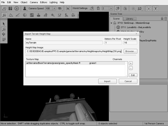
21. Type a name in for your terrain. Don’t use “Terrain”—that’s a reserved word. You can, however, use “myTerrain”, or “testTerrain”, or even “planetXenon”, for that matter. The default is “theTerrain”, but you should use your own name as a means of recognizing which files are your own creations.
22. Set the Meters Per Pixel to 1.
23. Set the Height Scale to 16. We are using this value because it is the number of discrete elevations we had in the earlier calculations, remember. You can fiddle with this number later to adjust the appearance of the elevations. I recommend also trying out 32 for the scale—see if it pleases.
24. Next we want to select our height map image. Use the image file you recently created, which should be a 256 pixel square image at 72 pixels/in. resolution. You can click on the Browse button to go look for the file. It should be in art errainsheightmaps.
25. After the height map, we need to specify an opacity mask. This is done by using an opacity map file. I have supplied general-purpose opacity masks in three different opacity map files in the grass folder inside the BookTerrains folder, which you can find in the chapter 12 folder in RESOURCES, all at 72 pixels/in. Copy this folder (it needs to be copied, we can’t properly use it from where it is) into the art errains folder of the example game. Then, to the right side of the box labeled Text Map, you will see a small plus (+) sign. Click on it, and you will be prompted to browse for and open an Opacity Map file. Browse your way to art errainsBookTerrains (the folder you copied earlier), then dig inside the grass folder to find the file grass_opacityMask256.png. Open it. You will now have an entry in the Texture Map box. Double-click on this entry to open the Terrain Materials Editor dialog shown in Figure 12.15.
Figure 12.15
Terrain Materials Editor dialog box.
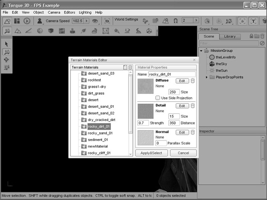
An opacity mask is a bitmap image that tells the terrain manager how to apply materials to the terrain. A white pixel in the opacity mask tells Torque to allow the corresponding pixel in the material to be rendered onto the terrain geometry. A black pixel tells Torque to not render the material at that location. Gray values indicate varying degrees of allowance of the material. You can have many opacity masks assigned to a terrain, each controlling the application of different materials. The image that contains an opacity mask is called an opacity map.
26. Choose a Material for the basic terrain coloring from the list on the left side. I used rocky_dirt_01, but you can choose any of them. We’ll learn how to create new ones later.
27. Click the Appy&Select button to exit the Terrain Materials Editor and then click Import at the lower-right of the Import Terrain Height Map dialog. There will be a pause of several seconds, and then you might see the terrain appear, depending on which way you are facing. If it seems a little drab in the terrain surface material department, fret not! We will add some surfaces later in the chapter.
After you’ve imported your terrain, you might find that you have trouble actually locating it. If this happens, switch to the world camera, and then look up or down. Most likely it will be above you. You can grab it by selecting it in the Scene tree on the right side, and then pull it down (or up) to your level by dragging the blue Z-axis control line. You need to make sure that your player spawn point and other object spawns are located above the terrain as well.
A Long-Winded Tip
As you may or may not be aware, after I’ve written or re-written each chapter of this book, a person called a Technical Editor (TE) runs through it, checks it for obvious (and sometimes not-so-obvious) technical goofs, and also performs every single procedure, following my instructions, just as you, the gentle reader, would.
When a problem is encountered, the TE puts a note in the body of the text. When the chapter comes back to me (after further copyediting by other editors) for Author Review (AR) I go through it looking for these comments, and then correct the problem in some way. Ninety-nine percent of the time I take the TE’s suggestion about how to fix a problem, and use it. Every once in a while, I take a vastly different, or maybe only slightly different approach to correcting the error. This tip is one of those approaches.
Here is a note from the TE:
See that? Simple, succinct description of the problem, with some mild hyperbole tossed in to ensure that the sense of the problem is communicated. And, as with all constructive criticism, steps for a correction are offered.
So, without further ado:
If you find yourself falling through space after spawning there are two methods you can use to recover.
In the first method, first look up. If you have fallen through the terrain, you should see it receding from you, upward. You might only see edges of hills and so on, but it will be obvious that something is up there, and you are moving away from it, rapidly.
The next thing you need to do is separate yourself from your falling body. You can do this by pressing F8, which switches you to the world camera, or puts you in what I call camera fly mode. Then look up, and “fly” up toward the terrain, until you are well above it. Then press F7 to spawn your body at the location where the camera is.
You should find yourself falling toward the ground in short order.
The second method (providing you’re running the FPS Example—other demos or your own game may not have the correct code or key binding for this) is to kill your character using the Ctrl-K key combo, which invokes the “Self Kill” or “Suicide” command. Your player will die, while falling, and respawn after you hit the spacebar or press the mouse button. As long as the next randomly chosen spawn point is above ground, you should be fine. If all of your spawn points have somehow ended up underground, then you should use the first method instead.
Once your falling problem is fixed, you can correct the spawnspheres by invoking the World Editor (F11), making sure you are in the Object Sub-Editor (F1), and putting the editor into translate mode (the 2 key). Then you can then select a spawnsphere by looking around until you see one, grabbing it, and dragging it upward by the blue arrow that sprouts from the top of spawnsphere object. Keep dragging it up until it is visible above the terrain. You can also select the spawnspheres by looking through the Scene tree on the right side of the screen.
You can select all of the spawnspheres by holding the Shift key down while clicking each one in turn. Then you can drag them all up to an appropriate location in one shot.
Oh yeah, and if you want to know who the TE is, look in the front of the book!
When you save your mission, the terrain data is also saved as a TER file in the levels folder. If you want, you can also import previously saved TER files rather than recreating height maps.
Note the reference to the newly created terrain file that is stored in the mission file in a TerrainBlock named “myTerrain”:
new TerrainBlock(myTerrain) {
   terrainFile = "levels/myTerrain.ter";
   castShadows = "1";
   squareSize = "1";
   baseTexSize = "1024";
   lightMapSize = "256";
   screenError = "16";
   position = "-127.957 -17.9646 -370.536";
   rotation = "1 0 0 0";
   canSave = "1";
   canSaveDynamicFields = "1";
};
Establishing Terrain Sizes
The height map we imported was created in Gimp, at 256 pixels square for the image size. When we imported it, we used a value of 1 for the “Meters per pixel” setting. This means that the resulting terrain block would be 256 meters by 256 meters in the game world. After years of being squishy on this issue, GG finally committed themselves to one World Unit (WU) being the same as one meter. Golf clap.
Changing the terrain squareSize in the mission file also affects the “resolution” in the Terrain Editor and the Terrain Painter; you will have more precision at smaller sizes, less “resolution” at larger sizes. The square size value is the same value you set when importing the terrain that was called “Meters per pixel”. Be sure to change the position values of the terrain if you change the square size. For example, if you want coarser features in your terrains, set the squareSize to 4 and the position to −1024, −1024,0:
   new TerrainBlock(myTerrain) {
      terrainFile = "levels/myTerrain.ter";
      squareSize = "4";
      tile = "1";
      position = "-1024 -1024 0";
      rotation = "1 0 0 0";
      scale = "1 1 1";
      canSaveDynamicFields = "1";
   };
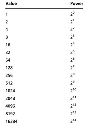
So if we want our terrain to represent a larger area, we can simply change to a larger squareSize value. Another way to make a larger terrain is to use the same squareSize, but to make the heightMap image larger, say 512 by 512 pixels (four times the terrain area) or 1024 by 1024 pixels (16 times the original terrain area). The sizes do not have to be square (although that is best), but they do have to be in powers of two.
The useful powers-of-two up to 16384 are shown in Table 12.3.
Using powers-of-two for image sizes should always be your default choice when dealing with images involved in real-time rendering, such as 3D modeling. This is because computer chips and graphics coprocessors can very quickly multiply and divide these values using a technique called register shifting, without needing to invoke a math coprocessor. A good book on computer chip design can tell you more, if you are curious.
“Painting” Terrains
Textures that will be used to create surface materials for terrains should be placed in a subdirectory in your game folder; you should probably put them in the terrains folder that lurks inside the art folder, but it isn’t strictly required. Just remember that good organization is always helpful and boosts productivity.
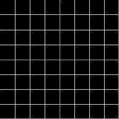
And although not a requirement, terrain surface textures will look best when they are created to be tiled, as discussed earlier; opposite edges should match so that when they are tiled you won’t be able to see the edges. The images in Figures 12.16 and 12.17 are test textures that are 256 pixels by 256 pixels. The checkerboard pattern in Figure 12.16 has each white or black section sized at 128 pixels by 128 pixels.
The grid texture in Figure 12.17 has white lines every 32 pixels and red lines at 128 pixels. You can use these images to calculate the total terrain size with respect to the dimensions of objects created in a map editor as well as to calculate the terrain square size with respect to terrain textures. In addition, you can use the image in Figure 12.17 to create sight lines when manually adjusting terrain heights. Torque 3D now includes its own textures with dimensions marked into the texture to help with sizing issues.
Figure 12.16
Checkerboard texture.

To paint the terrain surface, follow these steps:
1. Open the FPS Example, Blank Room with the World Editor button in the Torque Toolbox.
2. Use the File, Open menu to locate and open the mission file you saved after you created the terrain from the height map.
3. Press Control-Q to switch to the world camera.
4. Fly up above the terrain a bit using the arrow keys to move and the mouse to aim and look down. You can use Control-W or Alt-C to switch out of the world camera whenever you want.
5. Locate the Terrain Painter toolbox button as shown in Figure 12.18 and click it.
Figure 12.18
World Editor Window menu with Terrain Painter selected.
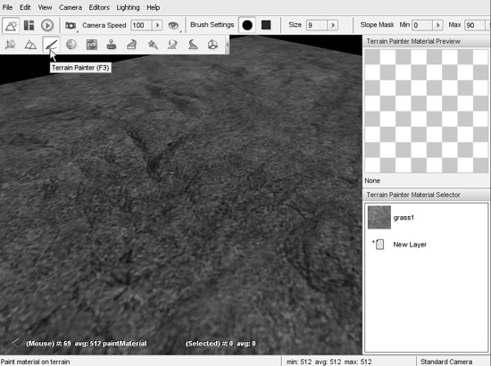
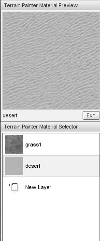
You will now see the Material Selection panel (as shown in Figure 12.19) to the right. You can highlight the material you want to paint with, or you can change or add new textures here. Note that each material is assigned a layer of its own. The topmost layer in the list is the layer at the “bottom” of the layer stack. New material layers are added at the bottom of the list in the panel, but are rendered “on top of” the previous layers, obscuring or blending with them as needed.
6. To add a new material layer, click on the New Layer button, and you will see the same Terrain Materials Editor we saw earlier, in Figure 12.15. You can choose an existing material from the list on the left, or create a new one. Let’s create a new one.
Figure 12.19
Material Selection panel.
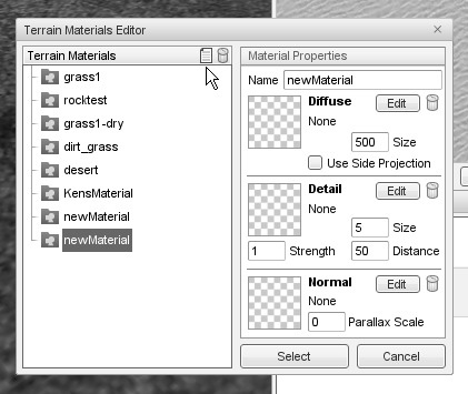
7. In the Terrain Materials Editor dialog, click on the New Material button—it looks like a small document icon to the left of the Trash Can icon, just left of center near the top of the dialog as shown by the arrow cursor in Figure 12.20.
8. This will create a new empty material entry with the default name new Material. On the right side in the Name field, type in a unique name for your material, like “myFirstMaterial”, or something.
9. Next, we need either a diffuse map texture or a detail map texture. Ideally, we will have both, sometimes accompanied by a normal map. Generally, the diffuse map will be used to provide color for our material, and the detail map will be used to provide definition, lines, details, marks, what-have-you—in other words, details. Let’s find a diffuse map to use. In the Diffuse pane, click on the Edit button. This will create an Open dialog in which we can find our desired texture.
Figure 12.20
New Material button in the Terrain Materials Editor.
10. Browse your way to art errainsBookTerrains ock and select the file rock_diffuseMap1024.png. Notice that none of the textures used within this material (diffuse, detail, normal) need to match either the height map or the opacity map, even though they often do.
11. Repeat steps 9 and 10 for the detail map texture pane and the normal map texture pane, locating the files rock_detailMap1024.png and rock_normalMap1024.png, situated in the same folder as the diffuse map.
12. After you have chosen all three textures for the material, click the Appy&Select button.
13. The new material is now in your selection set, similar to Figure 12.21, on the right side.
14. Now go up to the Size control, visible at the top in Figure 12.21, click the arrow to the right of the size box, and move the slider to obtain your desired brush size. You can also type the size into the Size field. After choosing your size, click on the word Size to commit to that selection.
Figure 12.22 depicts a texture applied with the brush size set to 1 (using the grid texture as a background for illustration purposes), and Figure 12.23 is a depiction of the corresponding terrain grid geometry.
Figure 12.21
Brush options and Terrain Materials selector.
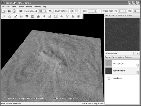
Figure 12.22
Painting terrain with a brush size set to 1.
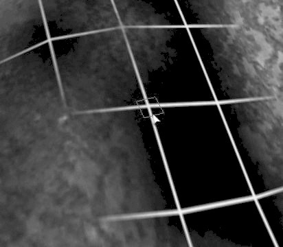
Figure 12.23
Depiction of terrain grid with a brush size set to 1.
So now take your trusty Terrain Paint Brush and go nuts!
MOVING RIGHT ALONG
So, now we understand why terrains need to be modeled and what our options are for obtaining real-world terrain data. If we aren’t modeling a real location, we’ve seen how we can create our own imaginary terrain using Gimp, so that we can satisfy the needs of our game. We also looked at terrain surface materials and how to create images for use as terrain surfaces.
Furthermore, we learned about some of the visual anomalies, like terrain tiling seams, which might make our terrains less pleasing, and how we can go about fixing those issues.
Earlier in the chapter, Figure 12.8 showed an example of a finished terrain, with some hills in the distance and terrain surfaces applied.
In the next chapter we’ll learn a pair of new tools, MilkShape and UVMapper.