Day 29 Network Data Flow from End-to-End
CCNA 640-802 Exam Topics
![]() Use the OSI and TCP/IP models and their associated protocols to explain how data flows in a network.
Use the OSI and TCP/IP models and their associated protocols to explain how data flows in a network.
![]() Determine the path between two hosts across a network.
Determine the path between two hosts across a network.
![]() Identify and correct common network problems at Layers 1, 2, 3 and 7 using a layered model approach.
Identify and correct common network problems at Layers 1, 2, 3 and 7 using a layered model approach.
Key Points
The exam topics for this day cover a wide range of content. Much of today’s review is a quick summary of the TCP/IP layers and their operations as data is sent from source to destination. Many of the key points will be fleshed out more fully in coming days. However, this is the only day we will discuss the operation of the transport layer. So we will spend quite a bit of time on the Transmission Control Protocol (TCP) and the User Datagram Protocol (UDP). We will also review basic troubleshooting methodologies.
The TCP/IP Application Layer
The application layer of the TCP/IP model provides an interface between software, like a web browser, and the network itself. The process of requesting and receiving a web page works like this:
-
HTTP request sent including an instruction to “get” a file—which is often a website’s home page.
-
HTTP response sent from the web server with a code in the header—usually either 200 (request succeeded and information is returned in response) or 404 (page not found).
The HTTP request and the HTTP response are encapsulated in headers. The content of headers allows the application layers on each end device to communicate. Regardless of the application layer protocol (HTTP, FTP, DNS, and so on), all use the same general process for communicating between application layers on the end devices.
The TCP/IP Transport Layer
The transport layer, through TCP, provides a mechanism to guarantee delivery of data across the network. TCP supports error recovery to the application layer through the use of basic acknowledgment logic. Adding to the process for requesting a web page, TCP operation works like this:
-
Web client sends an HTTP request for a specific web server down to the transport layer.
-
TCP encapsulates the HTTP request with a TCP header.
-
Lower layers process and send the request to the web server.
-
Web server receives HTTP requests and sends a TCP acknowledgement back to the requesting web client.
-
Web server sends the HTTP response down to the transport layer.
-
TCP encapsulates the HTTP data with a TCP header.
-
Lower layers process and send the response to the requesting web client.
-
Requesting web client sends acknowledgement back to the web server.
If data is lost at any point during this process, it is TCP’s job to recover the data. HTTP at the application layer does not get involved in error recovery.
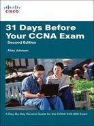
In addition to TCP, the transport layer provides UDP—a connectionless, unreliable protocol for sending data that does not require nor need error recovery. Table 29-1 lists the main features supported by the transport protocols. The first item is supported by TCP and UDP. The remaining items are supported only by TCP.
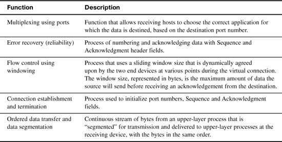
TCP provides error recovery, but to do so, it consumes more bandwidth and uses more processing cycles than UDP. TCP and UDP relies on IP for end-to-end delivery. TCP is concerned with providing services to the applications of the sending and receiving computers. To provide all these services, TCP uses a variety of fields in its header. Figure 29-1 shows the fields of the TCP header.

Port Numbers
The first two fields of the TCP header—source and destination ports—are also part of the UDP header shown later in Figure 29-6. Port numbers provide TCP (and UDP) a way to multiplex multiple applications on the same computer. Web browsers now support multiple tabs or pages. Each time you open a new tab and request another web page, TCP assigns a different source port number and sometimes multiple port numbers. For example, you might have five web pages open. TCP will almost always assign destination port 80 for all five sessions. However, the source port for each will be different. This is how TCP (and UDP) multiplexes the conversation so that the web browser knows in which tab to display the data.
Source ports are usually dynamically assigned by TCP and UDP from the range starting 1024. Port numbers below 1024 are reserved for well-known applications. Table 29-2 lists several popular applications and their well-known port numbers.

Error Recovery
Also known as reliability, TCP provides error recovery during data transfer sessions between two end devices who have established a connection. The sequence and acknowledgment fields in the TCP header are used to track every byte of data transfer and ensure that missing bytes are retransmitted.
In Figure 29-2, the Acknowledgment field sent by the web client (4000) implies the next byte to be received; this is called forward acknowledgment.

Figure 29-3 depicts the same scenario, except that now we have some errors. The second TCP segment was lost in transmission. Therefore, the web client replies with an ACK field set to 2000. The web server will now resend data starting at segment 2000. In this way, lost data is recovered.

Although not shown, the web server also sets a retransmission timer, awaiting acknowledgment, just in case the acknowledgment is lost or all transmitted segments are lost. If that timer expires, the web server sends all segments again.
Flow Control
Flow control is handled by TCP through a process called windowing. The two end devices negotiate the window size when initially establishing the connection; then they dynamically renegotiate window size during the life of the connection, increasing its size until it reaches the maximum window size of 65,535 bytes or until errors occur. Window size is specified in the window field of the TCP header. After sending the amount of data specified in the window size, the source must receive an acknowledgment before sending the next window size of data.
Connection Establishment and Termination
Connection establishment is the process of initializing sequence and acknowledgment fields and agreeing on port numbers and window size. The three-way connection establishment phase shown in Figure 29-4 must occur before data transfer can proceed.

In the figure, DPORT and SPORT are the destination and source ports. SEQ is the sequence number. In bold are SYN and ACK, which each represent a 1-bit flag in the TCP header used to signal connection establishment. TCP initializes the Sequence Number and Acknowledgment Number fields to any number that fits into the 4-byte fields.
After data transfer is complete, a four-way termination sequence occurs that uses an additional flag, called the FIN bit, as shown in Figure 29-5.

UDP
TCP establishes and terminates connections between endpoints, whereas UDP does not. Therefore, UDP is called a connectionless protocol. It provides no reliability, no windowing, no reordering of the data, and no segmentation of large chunks of data into the right size for transmission. However, UDP does provide data transfer and multiplexing using port numbers, and it does so with fewer bytes of overhead and less processing than TCP. Applications that use UDP are ones that can trade the possibility of some data loss for less delay, such as VoIP. Figure 29-6 compares the two headers.
The TCP/IP Internet Layer
The Internet layer of the TCP/IP model and its Internet Protocol (IP) defines addresses so that each host computer can have a different IP address. In addition, the Internet layer defines the process of routing so that routers can determine the best path to send packets to the destination. Continuing with the web page example, IP addresses the data as it passes from the transport layer to the Internet layer:
-
Web client sends an HTTP request.
-
TCP encapsulates the HTTP request.
-
IP encapsulates the transport segment into a packet, adding source and destination addresses.
-
Lower layers process and send the request to the web server.
-
Web server receives HTTP requests and sends a TCP acknowledgement back to the requesting web client.
-
Web server sends the HTTP response down to the transport layer.
-
TCP encapsulates the HTTP data.
-
IP encapsulates the transport segment into a packet, adding source and destination addresses.
-
Lower layers process and send the response to the requesting web client.
-
Requesting web client sends acknowledgement back to the web server.
The operation of IP not only includes addressing, but also the process of routing the data from source to destination. IP will be further discussed and reviewed in the upcoming days.
The TCP/IP Network Access Layer
IP depends on the network access layer to deliver IP packets across a physical network. Therefore, the network access layer defines the protocols and hardware required to deliver data across some physical network by specifying exactly how to physically connect a networked device to the physical media over which data can be transmitted.
The network access layer includes a large number of protocols to deal with the different types of media that data can cross on its way from source device to destination device. For example, data might need to travel first on an Ethernet link, then cross a Point-to-Point (PPP) link, then a Frame Relay link, then an Asynchronous Transfer Mode (ATM) link, and then finally an Ethernet link to the destination. At each transition from one media type to another, the network access layer provides the protocols, cabling standards, headers, and trailers to send data across the physical network.
Many times, a local link address is needed to transfer data from one hop to the next. For example, in an Ethernet LAN, Media Access Control (MAC) addresses are used between the sending device and its local gateway router. At the gateway router—depending on the needs of the outbound interface—the Ethernet header might be replaced with a Frame Relay header that will include data-link connection identifier (DLCI) addresses. In Frame Relay, DLCI addresses serve the same purpose as MAC addresses in Ethernet—to get the data across the link from one hop to the next so that the data can continue its journey to the destination. Some protocols, such as Point-to-Point Protocol (PPP), do not need a link address because only one other device is on the link that can receive the data.
With the network access layer, we can now finalize our web page example. The following greatly simplifies and summarizes the process of requesting and sending a web page:
-
Web client sends an HTTP request.
-
TCP encapsulates the HTTP request.
-
IP encapsulates the transport segment into a packet, adding source and destination addresses.
-
Network access layer encapsulates packet in a frame, addressing it for the local link.
-
Network access layer sends the frame out as bits on the media.
-
Intermediary devices process the bits at the network access and Internet layers, and then forward the data toward the destination.
-
Web server receives the bits on the physical interface and sends up through the network access and Internet layers.
-
Web server sends a TCP acknowledgement back to the requesting web client.
-
Web server sends the HTTP response down to the transport layer.
-
TCP encapsulates the HTTP data.
-
IP encapsulates the transport segment into a packet, adding source and destination addresses.
-
Network access layer encapsulates packet in a frame, addressing it for the local link.
-
Network access layer sends the frame out as bits on the media.
-
Lower layers process and send the response to the requesting web client.
-
Response travels back to the source over multiple data links.
-
Requesting web client receives response on the physical interface and sends the data up through the network access and Internet layers.
-
Requesting web client sends a TCP acknowledgement back to the web server.
-
Web page is displayed in requesting device’s browser.
Data Encapsulation Summary
Each layer of the TCP/IP model adds its own header information. As the data travels down through the layers, it is encapsulated with a new header. At the network access layer, a trailer is also added. This encapsulation process can be described in five steps:
Step 1 Create and encapsulate the application data with any required application layer headers. For example, the HTTP OK message can be returned in an HTTP header, followed by part of the contents of a web page.
Step 2 Encapsulate the data supplied by the application layer inside a transport layer header. For end-user applications, a TCP or UDP header is typically used.
Step 3 Encapsulate the data supplied by the transport layer inside an Internet layer (IP) header. IP is the only protocol available in the TCP/IP network model.
Step 4 Encapsulate the data supplied by the Internet layer inside a network access layer header and trailer. This is the only layer that uses both a header and a trailer.
Step 5 Transmit the bits. The physical layer encodes a signal onto the medium to transmit the frame.
The numbers in Figure 29-7 correspond to the five steps in the list, graphically showing the same encapsulation process.

Note The letters LH and LT stand for link header and link trailer, respectively, and refer to the data link layer header and trailer.
Using Layers to Troubleshoot
You should already have extensive experience troubleshooting network problems—whether in an actual work environment, in a lab environment, or a combination of both. By now, you have developed your own troubleshooting methodology. Maybe you like to check the physical layer first. Is the cabling correct? Are all interface status lights green? Maybe you like to ping everything to gather information about where connectivity is lacking. Then you use the results of your connectivity tests to isolate problems and drill down deeper. Maybe you just intuitively search for solutions, using your past experience to guide.
Regardless of your method, a systematic troubleshooting methodology can help you troubleshoot problems more efficiently and with better success. There are three main methods for troubleshooting networks using the layers of the OSI model:
![]() Bottom up: Start with the physical components and move up through the layers until the problem is isolated. Use this approach when the problem is suspected to be a physical one. Most networking problems reside at the lower levels, so implementing the bottom-up approach often results in effective results.
Bottom up: Start with the physical components and move up through the layers until the problem is isolated. Use this approach when the problem is suspected to be a physical one. Most networking problems reside at the lower levels, so implementing the bottom-up approach often results in effective results.
![]() Top down: Start with the end-user application and move down through the layers until the problem is isolated. Use this approach for simpler problems or when you think the problem is with a piece of software.
Top down: Start with the end-user application and move down through the layers until the problem is isolated. Use this approach for simpler problems or when you think the problem is with a piece of software.
![]() Divide and conquer: Start by collecting user experience, documenting the symptoms, and then, using that information, make an informed guess at which OSI layer to start your investigation. After you verify that a layer is functioning properly, assume that the layers below it are functioning, and work up the OSI layers. If an OSI layer is not functioning properly, work your way down the OSI layer model.
Divide and conquer: Start by collecting user experience, documenting the symptoms, and then, using that information, make an informed guess at which OSI layer to start your investigation. After you verify that a layer is functioning properly, assume that the layers below it are functioning, and work up the OSI layers. If an OSI layer is not functioning properly, work your way down the OSI layer model.
To effectively troubleshoot network problems, take the time to select the most effective network troubleshooting method. Today we are just reviewing the general methods used to troubleshoot network problems. In the coming days, we discuss troubleshooting in more detail as we explore implementation-specific situations in switching and routing technologies.