Day 17 Connecting and Booting Routers
CCNA 640-802 Exam Topics
![]() Select the appropriate media, cables, ports, and connectors to connect routers to other network devices and hosts.
Select the appropriate media, cables, ports, and connectors to connect routers to other network devices and hosts.
![]() Describe the operation of Cisco routers (including router bootup process, POST, router components).
Describe the operation of Cisco routers (including router bootup process, POST, router components).
Key Topics
Today we review basic router components, the router bootup process, router interfaces, and connecting to routers. The content for today’s review is rather light. Take this opportunity to review more difficult material from previous days or move on to the next day when you’re done here. You might also simply take a break.
Router Internal Components
Similar to a PC, a router also includes the following internal components:
![]() CPU: Executes the operating system instructions, such as system initialization, routing functions, and network interface control.
CPU: Executes the operating system instructions, such as system initialization, routing functions, and network interface control.
![]() RAM: Volatile memory that stores data structures needed by the CPU while the router is powered, including
RAM: Volatile memory that stores data structures needed by the CPU while the router is powered, including
— Operating system: Cisco IOS Software is copied into RAM during bootup.
— Running configuration file: Stores the configuration commands that the router’s IOS is currently using.
— IP routing table: Stores information about directly connected and remote networks.
— ARP cache: Similar to the ARP cache on a PC.
— Packet buffering: Packets are temporarily stored in a buffer when received on an interface or before they exit an interface.
![]() ROM: A form of permanent storage used to store
ROM: A form of permanent storage used to store
— Bootstrap instructions
— Basic diagnostic software
— Scaled-down version of IOS
![]() Flash memory: Flash memory is nonvolatile computer memory that can be electrically erased and reprogrammed. Flash is used as permanent storage for the Cisco IOS.
Flash memory: Flash memory is nonvolatile computer memory that can be electrically erased and reprogrammed. Flash is used as permanent storage for the Cisco IOS.
![]() NVRAM: Nonvolatile random-access memory, which does not lose its information when the power is turned off. NVRAM is used by Cisco IOS Software as permanent storage for the startup configuration file.
NVRAM: Nonvolatile random-access memory, which does not lose its information when the power is turned off. NVRAM is used by Cisco IOS Software as permanent storage for the startup configuration file.
IOS
The operating system software used in Cisco routers is known as Cisco Internetwork Operating System (IOS). Like any operating system on any other computer, Cisco IOS Software is responsible for managing the hardware and software resources of the router, including allocating memory, managing processes and security, and managing file systems. Cisco IOS is a multitasking operating system that is integrated with routing, switching, internetworking, and telecommunications functions. Although Cisco IOS Software might appear to be the same on many routers, there are many different IOS images. Cisco creates many IOS images, depending on the model and the features within IOS. Typically, additional features require more flash and RAM to store and load IOS.
As with other operating systems, Cisco IOS has its own user interface. Although some routers provide a graphical user interface (GUI), the command-line interface (CLI) is a much more common method of configuring Cisco routers.
Router Bootup Process
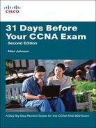
Like all computers, a router uses a systematic process to boot. This involves testing the hardware, loading the operating system software, and performing any saved configuration commands in the saved startup configuration file. Some of the details of this process have been excluded and are examined more completely in a later course.
Figure 17-1 shows the six major phases in the bootup process:
-
Power-On Self Test (POST): Testing the router hardware
-
Loading the bootstrap program
-
Locating Cisco IOS
-
Loading Cisco IOS
-
Locating the configuration file
-
Loading the startup configuration file or entering setup mode
Use the show version command to verify and troubleshoot some of the basic hardware and software components of a router. The show version command in Example 17-1 displays information about the version of Cisco IOS Software currently running on the router, the version of the bootstrap program, and information about the hardware configuration, including the amount of system memory.
Example 17-1 show version Command Output
Router#show version
Cisco Internetwork Operating System Software
IOS (tm) C2600 Software (C2600-I-M), Version 12.2(28), RELEASE SOFTWARE (fc5)
Technical Support: http://www.cisco.com/techsupport
Copyright (c) 1986-2005 by cisco Systems, Inc.
Compiled Wed 27-Apr-04 19:01 by miwang
Image text-base: 0x8000808C, data-base: 0x80A1FECC
ROM: System Bootstrap, Version 12.1(3r)T2, RELEASE SOFTWARE (fc1)
Copyright (c) 2000 by cisco Systems, Inc.
ROM: C2600 Software (C2600-I-M), Version 12.2(28), RELEASE SOFTWARE (fc5)
System returned to ROM by reload
System image file is "flash:c2600-i-mz.122-28.bin"
cisco 2621 (MPC860) processor (revision 0x200) with 60416K/5120K bytes of memory.
Processor board ID JAD05190MTZ (4292891495)
M860 processor: part number 0, mask 49
Bridging software.
X.25 software, Version 3.0.0.
2 FastEthernet/IEEE 802.3 interface(s)
2 Low-speed serial(sync/async) network interface(s)
32K bytes of non-volatile configuration memory.
16384K bytes of processor board System flash (Read/Write)
Configuration register is 0x2102
Router Ports and Interfaces
Figure 17-2 shows the back side of a 2621 router with management ports and interfaces labeled.

Management ports are not used for packet forwarding like Ethernet and serial interfaces, but are used to connect a terminal to the router and configure it without network access. The console port must be used during initial configuration of the router. The auxiliary port can provide remote management if a modem is attached.
Routers have multiple interfaces used to connect to multiple networks. For example, a router will most likely have Fast Ethernet interfaces for connections to different LANs and also have different types of WAN interfaces used to connect a variety of serial links, including T1, DSL, and ISDN.
Router Connections
Connecting a router to a network requires a router interface connector to be coupled with a cable connector. As you can see in Figure 17-3, Cisco routers support many serial connectors including EIA/TIA-232, EIA/TIA-449, V.35, X.21, and EIA/TIA-530 standards.

For Ethernet-based LAN connections, an RJ-45 connector for the unshielded twisted-pair (UTP) cable is most commonly used.
Two types of cables can be used with Ethernet LAN interfaces:
![]() A straight-through, or patch, cable, with the order of the colored pins the same on each end of the cable
A straight-through, or patch, cable, with the order of the colored pins the same on each end of the cable
![]() A crossover cable, with pin 1 connected to pin 3 and pin 2 connected to pin 6
A crossover cable, with pin 1 connected to pin 3 and pin 2 connected to pin 6
Straight-through cables are used for the following connections:
![]() Switch-to-router
Switch-to-router
![]() Hub-to-router
Hub-to-router
![]() Switch-to-PC/server
Switch-to-PC/server
![]() Hub-to-PC/server
Hub-to-PC/server
Crossover cables are used for the following connections:
![]() Switch-to-switch
Switch-to-switch
![]() PC/server-to-PC/server
PC/server-to-PC/server
![]() Switch-to-hub
Switch-to-hub
![]() Hub-to-hub
Hub-to-hub
![]() Router-to-router
Router-to-router
![]() Router-to-PC/server
Router-to-PC/server
Connecting to a router through its wireless interface will be reviewed on Day 9, “Configuring and Troubleshooting Wireless Networks.”