
Let's now have a look at the types of rendering pipeline in Android.
In the case of the 2D Android drawing system through Canvas, all the assets are first drawn on the canvas, and the canvas is rendered on screen. The graphic engine maps all the assets within the finite Canvas according to the given position.
Often, developers use small assets separately that cause a mapping instruction to execute for each asset. It is always recommended that you use sprite sheets to merge as many small assets as possible. A single draw call can then be applied to draw every object on the Canvas.
Now, the question is how to create the sprite and what the other consequences are. Previously, Android could not support images or sprites of a size more than 1024 x 1024 pixels. Since Android 2.3, the developer can use a 4096 x 4096 sprite. However, using such sprites can cause permanent memory occupancy during the scopes of all the small assets. Many low-configuration Android devices do not support such large images to be loaded during an application. It is a best practice that developers limit themselves to 2048 x 2048 pixels. This will reduce memory usage peak, as well as significant amounts of draw calls to the canvas.
Android uses OpenGL to render assets on the screen. So, the rendering pipeline for Android 3D is basically the OpenGL pipeline.
Let's have look at the OpenGL rendering system:
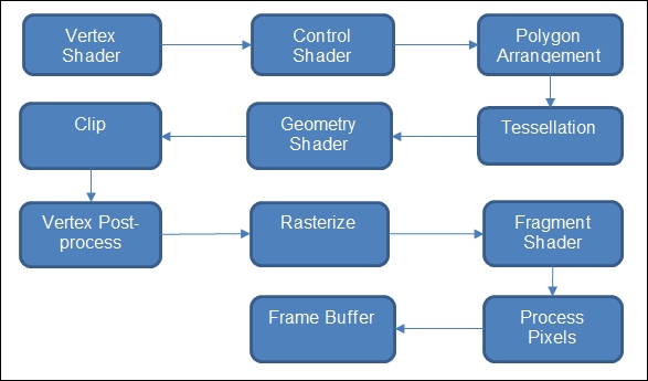
Now, let's have a detailed look at each step of the preceding rendering flow diagram:
- The vertex shader processes individual vertices with vertex data.
- The control shader is responsible for controlling vertex data and patches for the tessellation.
- The polygon arrangement system arranges the polygon with each pair of intersecting lines created by vertices. Thus, it creates the edges without repeating vertices.
- Tessellation is the process of tiling the polygons in a shape without overlap or any gaps.
- The geometry shader is responsible for optimizing the primitive shape. Thus triangles are generated.
- After constructing the polygons and shapes, the model is clipped for optimization.
- Vertex post processing is used to filter out unnecessary data.
- The mesh is then rasterized.
- The fragment shader is used to process fragments generated from rasterization.
- All the pixels are mapped after fragmentation and processed with the processed data.
- The mesh is added to the frame buffer for final rendering.