
Reactive Power Plant and FACTS Controllers
Variations of voltage with load 41.3
The flow of power and vars 41.3.1
Var balancing for steady state conditions 41.3.3
Power transmission over long distances 41.3.4
The development of FACTS controllers 41.5
Synchronous compensators 41.5.1
Sign convention for vars and reactive current 41.5.2
Basic features of static compensation 41.5.3
Mechanically switched reactors and capacitors 41.6.2
Synchronous compensators 41.6.3
Controllers with shunt and series components 41.8
41.1 Introduction
When designing a transmission or distribution system or studying its operation, the engineer must take into account not only the power requirement of the loads, but also the fact that they consume reactive power and, equally important, that the networks include inductive and capacitive elements which themselves absorb or generate reactive power. In contrast to power, which is generated and consumed in a controlled manner only at specific points in the networks (ignoring losses), reactive power is generated and absorbed throughout the network in significant quantities which vary with the system loading and configuration.
Growth in the demand for energy, the development of competition for the production and supply of this energy, together with increasing opposition to the construction of new overhead power lines, make it increasingly important to improve the utilisation of existing assets. However, there are constraints on the operation of power systems that often result in under-utilisation of their assets.
For a power system to operate efficiently and securely, the importance of the correct and co-ordinated provision and control of reactive power cannot be overemphasised. It is necessary to examine reactive power requirements under both steady-state and dynamic conditions. Although it has been normal in the past to consider these requirements separately, it is preferable that they should be dealt with in a well-co-ordinated way.
‘FACTS’ is an acronym for ‘Flexible AC Transmission Systems’, which is defined as ‘alternating current transmission systems incorporating power electronic-based and other static controllers to enhance controllability and increase power transfer capability’. Many of the reactive power plant items described in this chapter are covered by this definition. FACTS equipment that provides control of one or more of the parameters of an electrical network is often referred to as a FACTS controller.
The International Electro technical Commission, IEC, has defined the unit for reactive power as the ‘var’ (volt-ampere reactive) and uses the name ‘vars’ for reactive power. For brevity, the IEC terminology will generally be used within this chapter.
41.2 Basic concepts
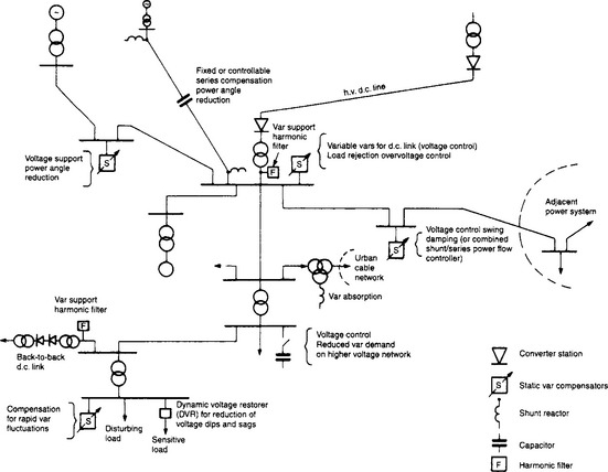
In electrical power systems, electrical energy is produced by generators, transferred by means of transformers into a transmission system by which it is conveyed to distribution systems and supplied, again via transformers, to the users of the energy. Figure 41.1 shows a system where different components and reactive power devices have been combined to illustrate the main features of var supply and demand in such a power system. The characteristics of individual components and the methods of network analysis are covered in other chapters. The following sections outline the characteristics and parameters relevant to the management and supply of vars, network voltage control and reactive compensation.
41.2.1 Characteristics of system components
The main generator parameters relevant to the var balance in a system are the transient reactance and the short-circuit ratio (SCR, which is approximately the reciprocal of the synchronous reactance). Where transient stability is to be examined, or where var control is required to be used for the damping of system oscillations, the inertia of the turbine-generator combination also needs to be known.
To obtain economies from standardisation, many manufacturers of turbogenerators will offer a machine from a standard range of frame sizes; different combinations of megawatts, rated power factor and short-circuit ratio are possible with each design of the range. The characteristics and capabilities of each generator must be allowed for in considering the overall var balance for a particular system.
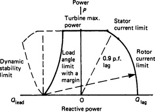
The frame size of a generator depends upon its megavolt-ampere (MVA) rating; hence, the cheapest design for a given megawatt output would be one rated to operate at unity power factor (pf). However, unity pf operation may not be acceptable for stability and optimum operation of the network. Operation of a generator at a lagging power factor, i.e. when generating vars, requires a higher level of field excitation than at unity pf; this reduces the generator load angle for a given power output. To prevent a generator losing synchronism during angular swings following a system disturbance, it is desirable to operate it in steady state with an adequate margin of load angle from its stability limit. A typical cylindrical-rotor turbogenerator will have an SCR in the range 0.45–0.6; this would require operation at around 0.9–0.95 lagging pf, as shown in the capability chart in Figure 41.2, if the generator is feeding into a reasonably strong system. Under these conditions the generator will be supplying a significant amount of vars to the system, amounting to 0.48–0.33 Mvar/MW of output.
When it is necessary for a generator to absorb vars (i.e. to operate at a leading pf), as occurs during light load conditions for generating stations supplying remote load centres through long high-voltage lines, the field excitation must be lower than that at unity pf. The generator must then be designed to maintain stability, which requires that positive excitation is needed under all conditions. This gives a design with an SCR of, say, 1.0–1.5. Such high values are common in salient-pole low-speed generators in hydroelectric stations, which account for most such applications. Such a high value is unusual in round-rotor turbogenerators and would require an unusually large machine for the MW output. It may be more appropriate to provide var absorption equipment within the transmission network in these circumstances.
The proportion of the system var requirements supplied by generators varies from system to system. In many systems, the high-voltage transmission network has a surplus of vars, i.e. its shunt capacitance generates more vars than are absorbed by the I2X losses in its series reactance—even under maximum-demand conditions. This allows the generators to operate at high power factors, even if the system loads themselves have low power factors. The operating pf may, in practice, be dictated more by stability than load requirements and it is quite usual for generators to be operated at a lagging pf higher than their rated value.
41.2.1.2 Transformers
Although generators are now becoming available which are suitable for connection directly to system voltages of 145 kV and higher, in most cases it is necessary to couple the generator to the transmission system by means of a transformer. Similarly, transformers are used to reduce the voltage level at the points of connection of the distribution companies and again for the supply of individual customers or groups of customers. They are also used between the different voltage levels used by the transmission company, or companies.
The transformer leakage reactances have great significance for the operation of the transmission system. Although the power loss and magnetising current of a transformer can be neglected when considering var flows, the var absorption in its leakage reactance (given by I2X) is important. During temporary network overvoltages, transformer cores may become saturated, resulting in abnormally high magnetising currents. Although the increased var consumption will assist in reducing the overvoltages, harmonic currents will be generated. In flowing through the network, these currents may excite undesired resonances which themselves can cause overvoltages.
On-load tap-changing of transformers is a useful function in the co-ordination of var control between various voltage levels within a system and for balancing var flows within a single voltage level. Two distinct practices occur with transformers used to interconnect different transmission voltage levels in a single system; a number of authorities, with a view to using transformers having the highest reliability, install fixed ratio transformers, whereas others use on-load tap-changers having a typical total range of 20–30%. For the interconnection of transmission networks to sub-transmission or distribution networks, the use of tap-changing transformers is almost universal.
41.2.1.3 Transmission lines and cables
Transmission lines and cables absorb vars in their series inductance. They also have an inherent capability to generate vars by their shunt capacitance, which causes a reactive ‘charging current’ to flow into the line. Both the series inductance and the shunt capacitance are distributed along the length of the line.
From the analytical point of view, cables are indistinguishable from overhead lines except that the ratio between shunt capacitance and series reactance is considerably higher. The use of cables in high-voltage networks is increasing because of the difficulties of building new overhead lines for electrical power transmission into urban areas and, to a more limited extent, for a.c. underwater links; the use of cables is still very small compared with overhead lines because of the cost disadvantages. Where cables are used in any quantity, their high shunt capacitance reduces the need for additional var generation at peak demand periods but increases the need for var absorption during low loading conditions.
When there is no load current flowing through a line or cable, it is found that the voltage at the receiving end of the line is higher than that at the sending end; this is caused by the flow of the capacitive charging current through the series inductance and is known as the Ferranti Effect. The magnitude of the voltage rise increases very rapidly with increasing length of the line, from only about 3% for 200 km to about 50% for 800 km. The magnitude of such a voltage rise within a transmission system must be limited (generally to either 5 or 10% above rated voltage), in order to avoid exceeding the safe limits of operation for the insulation of the line or cable itself as well as the safe limits for the various equipment connected to the transmission system. Very long lines are normally split into sections 200 to 300 km long; voltage or var control measures can then be applied at the intervening substations, if required.
As the power flowing through the line is increased, the var absorption in the series reactance also increases. There is a critical current at which the magnitude of ‘series vars’ absorbed in the line is just enough to balance the ‘shunt vars’ generated by the shunt capacitance of the line. With this level of power flow, the line voltage will have the same value all along the line (neglecting resistive losses). When there is a further increase in power flowing through the line, the vars absorbed will outweigh the vars generated and the voltage at the receiving end of the line will start to fall very rapidly with increasing load and may reach the point of complete collapse.
The surge impedance of a transmission line having series inductance L and shunt capacitance C, is a resistance equal to (L/C). If a load that has this value of resistance is connected to the end of the line, the power that flows into the load is called the surge-impedance load or SIL. This is the load, mentioned above, at which the var absorption in the series reactance equals the var generation in the shunt capacitance, and for which the voltage along the line is constant. For a given surge impedance, the SIL increases in proportion to the square of the line voltage.
The value of surge impedance for a 132 kV line is about 400 Ω. For higher voltage systems, multiple conductors are normally used, in part to reduce corona effects, and the series inductance is also somewhat lower, giving a surge impedance of about 250 to 300 Ω for a 400 kV line. One effect of choosing an increased transmission voltage is to reduce transmission losses at a given power flow, but another effect is to enable an improved power transmission capability per right of way. In selecting a transmission voltage, therefore, a balance must be struck between equipment costs, operating costs and future capacity.
The SIL of typical cables usually exceeds their rating, so that cables generate more vars than they absorb and compensation is often required. This imposes a limit to the uninterrupted length of cable that can be used; for example, for submarine cables the limit is typically 50–75 km before the capacitive charging current reaches the current rating of the cable.
Cables that use cross-linked polyethylene (XLPE) insulation are now available for transmission voltages of 400–500 kV; for a 400 kV, 1100 MVA XLPE cable design, the SIL is about 2500 MW, which is still much higher than the rating. Nevertheless, these cables generate rather less charging current than the earlier types and allow uninterrupted lengths of up to about 100 km. Where longer distances are required, another solution becomes necessary, for example, h.v.d.c. or a gas-insulated transmission line (GIL).
Most countries have two or three transmission voltage levels within their systems, the highest normally being in the 400-500 kV range, with a few countries in North and South America and the USSR operating or installing networks in the 750 kV range. Although the use of u.h.v at 1000–1500 kV is technically feasible, the expense is high and its commercial application seems likely to be limited for the foreseeable future.
41.2.1.4 Loads
In general, loads are inductive and their power factor can vary widely, dependent on type, from industrial through commercial to domestic loads, and on location (for example, commercial and domestic loads in hot climates have an increasing proportion of motors for air conditioning). For most studies, load representation as constant impedances (or constant P and Q) is adequate but, when studying dynamic conditions involving wide variations in voltage, a more detailed representation that allows for changing power factors will be required. Power-factor-correction (pfc) capacitor banks located in load and distribution networks should also be taken into account in any studies.
Air-conditioning and many industrial loads use induction motors; when these comprise a substantial proportion of the total load on a network they display a typical voltage stability challenge. A short interruption due to a fault causes each motor to slow down. When the fault is removed and the voltage re-established the motor tries to regain full speed but, because of the increased slip, there is an increased var demand. The effect of many such loads is to depress the system voltage so much that recovery from a fault is slow and, in extreme cases, voltage collapse stability may be threatened and all load motors may stall.
Loads that can produce network disturbances or distortions require special attention. These are, in the main, found in the metal and mining industries and in a.c. traction systems; the large and rapid fluctuations in the load currents of arc furnaces and large thyristor drives, particularly their fluctuating var demands, can cause annoyance to other customers. These loads often also cause problems due to the generation of harmonics.
41.3 Variations of voltage with load
For each part of a power system it is necessary to define a nominal operating voltage and also a maximum operating voltage, which is usually 5% or 10% higher than the nominal voltage; these voltages are used in establishing the rated voltages of circuits and components. The rated MVA capacity of each circuit or component is then determined on the basis of its rated current and rated voltage. When an item is required to operate at its rated capacity but at less than its rated voltage, the current will exceed its rated value; this overload condition may only be acceptable for limited periods when the ambient temperature is less than the defined maximum value.
It is therefore usual to try to operate a system in steady state so that the voltage is constrained, throughout the system, to be within a very few per cent above or below its nominal value. Wider deviations of voltage are inevitable during and following faults and other disturbances. The most severe transient and switching overvoltages are usually limited by means of surge arresters; slower, dynamic or long-term, overvoltages and undervoltages may require var compensation equipment to reduce their magnitudes and durations to acceptable levels.
41.3.1 The flow of power and vars
Electricity supply networks have predominantly inductive series impedances. Figure 41.3(a) shows an elementary circuit in which a load is supplied from a generator via inductance, X. The generator output voltage, Vs, is constant; the voltage at the load is VR. When there is no load, the voltages Vs and VR are equal in magnitude and phase. When a load is connected it will draw a current, I, through X.
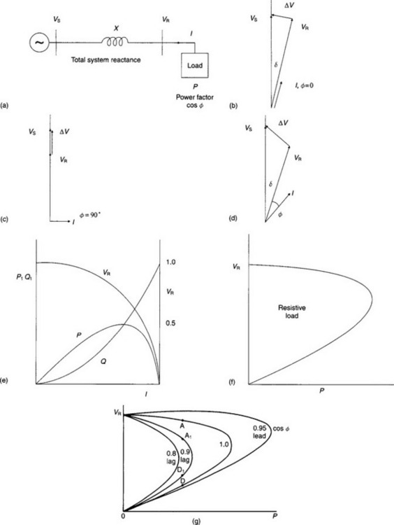
Figure 41.3(b) shows the vector diagram for a resistive load; I is in phase with VR and φ = 0. If the value of the load resistance is R, the power is P = VR · I = I2·R = VR2/R. The voltage drop through the reactance X, is ΔV = I · X and is in quadrature with VR. It causes a phase angle difference, δ, between Vs and VR. Also, VR is smaller than Vs because of the vars (Q = I2X) consumed in X.
Figure 41.3(c) shows the vector diagram for a purely inductive load, with I lagging by φ = 90° behind VR. The voltage drop through X is in now in phase with VR, which therefore remains in phase with Vs but is appreciably smaller. Figure 41.3(d) is the general case, with a lagging power factor load that causes differences both of phase angle and magnitude between Vs and VR.
These examples illustrate that, when power flows through inductive impedance from one point to another, it is accompanied by a difference in the phase angles of the voltage at those points. Var flow between two points is accompanied by a difference in the voltage magnitudes at those points. It is important to bear in mind that these features may be expressed in the converse way. Thus, when a difference in phase angle is enforced between the voltage vectors at two points in a network, power will be transmitted from one point to the other; by enforcing a difference between the voltage magnitudes at the two points; var flow will take place. Put simply, differences in phase angle control the flow of power and differences in voltage magnitude control the flow of vars. This is a highly simplified, but crucial, description of the principles of a.c. power transmission; reference should be made to Chapters 3 and 35 for the theoretical background.
41.3.2 Voltage instability
Figure 41.3(e) plots the relationships between power, vars and current supplied by the generator, together with the load voltage, VR for the purely resistive load illustrated by Figure 41.3(b). As the magnitude of load resistance, R, is reduced, the current, power and vars each increase at different rates, but VR decreases. When R is equal to X, P = Q, ![]() and δ = 45°. For this load resistance, the power has its maximum value, given by
and δ = 45°. For this load resistance, the power has its maximum value, given by ![]() . Any further reduction of resistance will cause a further reduction of VR and also of P whereas Q continues to increase. Figure 41.3(f) plots the relationship between voltage VR and power P and shows how important it is, for the stable operation of a system, that voltages at load points should not be allowed to drop below certain limits. If the load voltage falls too far, the condition can become progressively worse, leading to a complete collapse of voltage. Such voltage instability is more prone to occur in systems with large inductive impedances and can be exacerbated by loads that tend to consume constant power and vars irrespective of the magnitude of their supply voltage. Loads of this kind include those that are supplied by transformers with on-load tap-changers, when the tap-changers have an automatic control which attempts to maintain a constant secondary voltage.
. Any further reduction of resistance will cause a further reduction of VR and also of P whereas Q continues to increase. Figure 41.3(f) plots the relationship between voltage VR and power P and shows how important it is, for the stable operation of a system, that voltages at load points should not be allowed to drop below certain limits. If the load voltage falls too far, the condition can become progressively worse, leading to a complete collapse of voltage. Such voltage instability is more prone to occur in systems with large inductive impedances and can be exacerbated by loads that tend to consume constant power and vars irrespective of the magnitude of their supply voltage. Loads of this kind include those that are supplied by transformers with on-load tap-changers, when the tap-changers have an automatic control which attempts to maintain a constant secondary voltage.
Figure 41.3(g) shows a family of voltage-load curves for different power factor loads, including the unity pf case of Figure 41.3(f). When the load current has a lagging component, i.e. is at less than unity pf, the maximum power capability will be smaller and the voltage for a given load will be reduced compared with Figure 41.3(f). For a particular power factor curve and for any power less than the maximum there are two operating points; points A, A1, etc., are stable (i.e. dVR/dP is negative) and points D, D1, etc., are unstable. The upper, stable, values represent possible system operating conditions; however, if the load is increased, or the load pf is decreased, the operating point moves towards the ‘nose’ of the curve, accompanied by a progressive reduction in voltage, which tends towards a complete collapse of the system.
Figure 41.3(g) includes the interesting result for a load with a leading pf. This increases both the load voltage and the maximum load that may be transferred.
The phenomenon of voltage instability has been the cause of, or a contributory factor in, a number of major system failures. The adequate provision and the correct control of the network var resources can play a vital role in preventing voltage instability.
41.3.3 Var balancing for steady state conditions
It is clear from the previous sections that there are significant benefits in local balancing of load vars by power factor correction. In addition to the improvement in load voltage conditions, the magnitude of the load current is reduced, which reduces transmission losses and releases circuit capacity for increased power transfer. Capacitors draw a reactive current that leads the voltage across their terminals and shunt capacitor banks provide a relatively economic means of improving the power factors of loads connected to a power supply system especially if the load is constant, or almost constant. When there is a slow variation of the load, shunt capacitors may be switched into or out of service to provide an approximate balance of the load vars. When the load varies quickly, it can no longer be regarded as ‘steady state’ and a compensating system that can be quickly controlled to counteract the load fluctuations must be used, as will be described later.
It is also clear that, if the vars absorbed in the supply inductance were to be reduced by series var balancing, the effective inductance of the supply would be reduced. The adverse effects of both active and reactive currents would then be lessened and the stability margin could be increased.
41.3.4 Power transmission over long distances
The use of reactive compensation to improve transient stability and so increase the amount of power that can be transmitted over given transmission lines is discussed next. In contrast to the example of a simple load discussed above, it is usual for machines to be present and to provide voltage sources within the systems at each end of the line.
41.3.5 Transmission characteristics
A number of performance features are associated with long distance transmission.
At light loads which are only a small fraction of SIL, or at energisation of the line from one end only, the distributed inductance and capacitance of the line can cause a large over-voltage due to the Ferranti effect; this must be countered by either (a) reducing the vars from the line capacitance by shunt reactive compensation, or (b) cancelling part of the line inductance by series reactive compensation.
The maximum power that can be transmitted down a long uncompensated line is limited by its series inductance and by the line surge impedance. Increase in transmitted power can be achieved by series or shunt reactive compensation.
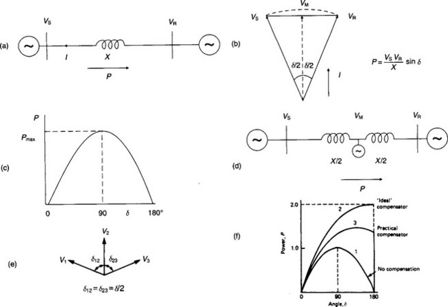
Figure 41.4(a) represents a long transmission line, with a total series inductive impedance X; to simplify this illustration, the effect of the line shunt capacitance is ignored. In Figure 41.4(b) the voltages Vs and VR at the two ends of the line are assumed to be maintained constant and equal for all values of current, I. As the current increases, so does the angle, δ, between the voltages. The voltage at the midpoint of the line will be
and, with Vs = VR, will be in phase with the line current.
The power flowing through the line will be
As shown in Figure 41.4(c) the transferred power rises to a maximum (given by ![]() ) as the angle δ reaches 90°. The power decreases as δ increases beyond 90°. It may be noted that control of the load voltage has doubled the power obtainable in the simple case illustrated in Section 41.3.2 where VR is not controlled.
) as the angle δ reaches 90°. The power decreases as δ increases beyond 90°. It may be noted that control of the load voltage has doubled the power obtainable in the simple case illustrated in Section 41.3.2 where VR is not controlled.
The shunt capacitance of a practical line will have the effect of increasing the voltage at all intermediate points along the line, including the mid-point, and consequently will give a corresponding increase in the maximum power. However, the voltage rise must not be allowed to exceed the maximum operating voltage of the system under no load or light load conditions.
Owing to the inertia of the rotating machines connected within the networks at either end of transmission lines, any system operating near its steady-state stability limit (corresponding to the phase angle of 90°) is bound to become unstable following a major disturbance, due to the ensuing increase of phase angles. It is therefore necessary to design a line to be able to transmit more than pre-fault power up to the point of maximum angular swing. Consequently, sufficient var generation must be available to compensate for the increased var consumption by the line current at increased phase angles. Thus, for transient stability to be secured, some excess var generation must be available. This can be achieved either by operating the line sufficiently below its surge impedance power before the fault or by adding var generation transiently for the period in which the line phase angle will be abnormally increased. However, without adequately fast voltage control along the line, either solution can lead to dangerous overvoltages, particularly under the condition of a severe ‘back-swing’ (i.e. a transient phase condition when the power transmitted is much less than the pre-fault level) or during a load rejection situation consequent to loss of stability.
Then the total vars Q to be absorbed from the line when operating at a voltage V and power P approximates to Q = Q0 [V2-(P/V)2] where Q0 is the vars generated by the line shunt capacitance, C, at rated voltage V1. Here P, Q, and Q0 are expressed in per-unit of the SIL, Ps, and V is expressed in per-unit of V1.
For V = 1 p.u., Q is equal to go at P = 0, and falls to zero for P = 1, i.e. for a power equal to PS. Power can be increased above PS, if Q can be made negative, i.e. if var generation is added.
41.3.6 Transient instability
There has been a tendency to increase the distance over which power is transmitted for the following typical requirements:
(a) the supply of large amounts of power to conurbations and industrial centres from economic, but distant, energy sources—e.g. hydroelectric or mine-mouth thermal stations;
(b) the supply of moderate amounts of power to areas remote from the power grid of the central region—i.e. by radial sub-transmission lines, having loads tapped at one or several locations along each line.
Transient instability can occur in a transmission system following a sudden disturbance such as a short-circuit. The power output of a generator located near a fault may be greatly reduced, thereby allowing its speed to increase, while the output of a remote generator may be hardly affected by the event. As the acceleration of the two generators will differ, the phase angle between their internal emfs will change. In a simple system the two generators will drop out of synchronism if the fault persists long enough to allow the phase angle between their emfs to swing too far above 90°. The loss of synchronism takes place usually within 1 s of the disturbance. It is clear that the larger the series inductive reactance of the transmission lines and system transformers in the network interconnecting the generators, the greater attention must be paid to the possibility of phase-angle instability. In a well-interconnected system that does not have long distances between generators, transient and dynamic instability is rarely a difficult problem because fast clearance times can be obtained by using modern relays and circuit breakers.
On the other hand, slow swings or oscillations may develop between two parts of the system (or perhaps between one remote generator and the rest of the system), possibly initiated by minor disturbances, and these may build up to unacceptable levels after perhaps 20 or 30 seconds. Modern automatic controllers for generator excitation, with auxiliary stabilising signals, can exert some damping on such oscillations. Shunt or series dynamic compensation may be used alternatively or in addition to generator excitation control.
41.3.7 Var balancing for dynamic conditions
Figure 41.4(d) represents the same transmission line as Figure 41.4(a) but with the assumption that the mid-point is connected to a virtual infinite bus-bar, which will always keep the magnitude of VM constant and equal to the voltages at the ends of the line. In this context, the ‘infinite busbar’ is not required to supply active power, (i.e. it will not control the phase angle of VM) but must behave as an ‘ideal’ FACTS controller to supply the vars required to control the voltage at the mid-point.
Figure 41.4(e) shows that this additional voltage support effectively divides the line into two equal sections, each with a reactance of X/2 and operating at an angle, δ/2. Each line section now has an independent stability limit which is reached when δ/2 = 90°. Thus the theoretical total angle between VS and VR can now be 180°, i.e. double the conventional critical value of 90°, with a resultant increase in power transfer capability.
Without any voltage support at the mid-point the power will be as in curve 1 of Figure 41.4(f) (repeated from Figure 41.4(c)).
With voltage support at the mid-point, the condition will be as in curves 2 and 3. If the vars were to be supplied instantaneously, the power transfer would be doubled (curve 2),
In practice it is not possible for the theoretical maximum to be achieved, owing to losses and the response delay of a practical controller (curve 3). However, it is possible to provide voltage support at several places along the line and so make up, to some extent, for the lack of the ‘ideal controller’.
Figure 41.5 illustrates an example of conditions to be expected on a very long high-voltage transmission line with voltage support, provided for example by SVCs (static var compensators) at two intermediate substations, Figure 41.5(a).
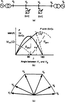
For each of the three sections there are two conditions that can be responsible for limiting the maximum power that is reached.
Assume that the controllers can hold the voltage rigidly constant irrespective of load. In this case the stability limit will theoretically be reached if the phase angle between two adjacent voltage controlled bus-bars reaches 90°. In practice, even with controllers, the resistance of the line and the controller response delays limit the total angle at maximum power to less than the theoretical maximum of 3 × 90°, e.g. to 175° in Figure 41.5(b). Figure 41.5(c) illustrates the phase angles of the line at this steady-state power limit.
The second limiting condition might be that any one of the controllers reaches the limit of its var generation capacity; the required vars from the controller are illustrated in Figure 41.5(b) by the curve Q (generation or absorption). When the power P and angle δ reach the condition of this limit, as for point ‘a’ in Figure 41.5(b), the controller ceases to be effective in controlling the line voltage at its point of connection and the stability limit is reached even if the total angle has not reached the expected limit (e.g. 175°).
The action of a shunt controller in improving the transmission capacity of a line can be thought of in terms of its effect on the natural surge impedance of the line; the shunt C is controlled so that the effective surge impedance matches the load being transferred. For heavy loads the shunt C is increased and the surge impedance is decreased, thereby increasing the value of SIL.
An alternative way of reducing the surge impedance in order to provide extra margin for a long transmission line is to reduce the series inductive reactance; this can be done by inserting a controller with a negative inductive reactance (usually in the form of capacitive reactance). Series compensation inserted in one or two locations along a transmission line has the following important characteristics.
(1) By reducing the effective series inductive reactance of a transmission line, series compensation allows a higher power transfer capability. This enhancement may provide a higher power over a given distance or enable a given power to be transmitted over a greater distance; alternatively, series compensation may be used to reduce the steady-state phase angle for a given power and distance.
(2) By increasing the (capacitive) vars generated as the load current increases, the series compensation improves the var balance in a line and hence reduces its voltage regulation, thereby reducing shunt var generation requirements at the line terminals.
Even when a long h.v. or e.h.v. line is series compensated, shunt reactors are normally needed to absorb part of the shunt vars of the line. Typically between 40% and 100% of line shunt capacitive power may be compensated at light load to prevent overvoltages on the line. To restrict insulation stresses caused by overvoltages following sudden load rejection, a substantial part of the shunt reactive compensation is usually left permanently connected; clearly, this reduces the maximum power limit of the line.
Figure 41.6(a) shows an illustrative theoretical example of the power–angle characteristic of a line including its terminal impedances; the line is represented as three π sections of about 200 km length each, with shunt reactors (R) at each line section terminal and series capacitors (C) at two intermediate locations. The curves in Figure 41.6(b) were calculated neglecting power losses, and the values are given in per-unit terms on the base of the surge impedance load (PS).
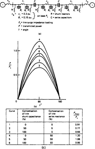
As the degree of shunt compensation is increased, the line requires a greater amount of series compensation to maintain the power–angle characteristics of the line. A comparison of curves 1 and 6 and the table in Figure 41.6(c) shows that with 100% shunt-reactor compensation the line requires almost 50% series compensation to reach the same maximum stable power limit as for the case without any shunt or series compensation. The maximum allowable limit of series capacitor compensation and choice of its location are governed not only by economic considerations, but also by various practical aspects, such as subsynchronous resonance (SSR, described later) and by the series capacitor short-circuit overcurrent protection needs. The latter requires spark gaps or non-linear resistors. The line distance protection relaying must be co-ordinated with these features.
41.4 The management of vars
Traditionally, a single organisation was responsible for all aspects of generation, transmission and distribution but, increasingly, these functions are being separated and allocated to organisations that are independent of each other. This subdivision of responsibilities usually results in competition between generating companies to supply power to the transmission network and often between distribution companies to supply power to customers, but the responsibility for transmission sometimes rests with a single organisation. The transmission company must then ensure that an adequate supply of energy is called up from the generators and that satisfactory levels of voltage exist throughout the transmission system in order to satisfy the moment by moment demands of the distribution companies; this requires the effective management of vars at the points where the energy is received and delivered, as well as within the transmission system itself. Adequate provision of vars at all times can be crucial for the security of a system.
It is necessary to balance various factors to arrive at an optimum solution for the management of vars. The objectives in such management must be both economic and technical.
(1) to optimise the capital investment in, and location of, plant for the generation and absorption of vars;
(2) to minimise system losses;
(3) to optimise plant utilisation, so postponing the need for system reinforcement;
(4) to obtain adequate system security;
41.4.2 Tools for var management
To attain the above objectives of efficient var management, system designers, operators and consumers can use some or all of the following types of plant or procedures: generators; on-load tap-changing transformers; switching of transmission circuits; various types of FACTS controller. Later sections provide information on the development and application of these controllers, which include shunt reactors and capacitor banks, switched or unswitched; series compensation; synchronous compensators; static var compensators; STATCOM; other FACTS controllers.
41.4.3 Var management by the supply authorities
The benefit of good var management by the supply authority can be significant. Three areas of management can be identified.
The first is in the system planning and design stage, where a choice must be made on the rating and type of any reactive compensation equipment to be used, where it should be connected in the network, and when is the optimum time for installation. The characteristics of any power system, particularly the proportion of generation connected at the different transmission voltage levels and the ratio between the system maximum and minimum loading, greatly influence the decisions to be made.
Most transmission networks, even at peak demand, operate below their surge impedance load and hence generate more vars than they absorb, i.e. they have a positive var balance. However, under emergency conditions following a loss of one or more lines, the positive balance may turn into a deficit which under extreme conditions can give problems of voltage instability as well as possible loss of synchronism due to the network’s low power-transfer capability.
A var planning study involves the balancing of the vars in the complete network. Then, after allocating an amount of var production to generating plant, it is necessary to decide on the best method to deal with the resultant surplus or deficit. For a large system this can require a protracted and major design exercise, and over the last two decades much effort has gone into the development of mathematical and computational techniques to aid system designers in this task.
The second area of var management is in system operation, where the facilities provided must be used in the most efficient manner to maximise system operational security and minimise system losses. Again much work has been done on the development of both off-line and on-line computer programs. Various studies have shown that, in general, minimising network losses also gives maximum security and minimum unnecessary circulation of vars in the network.
The third area is the commercial one of tariff policy, in which financial incentives are adopted to persuade consumers to maintain a power factor close to unity.
41.4.4 Var management by consumers
The induction motor is by far the most common driving machine and, in consequence, the natural power factor of most industrial loads is in the 0.7–0.8 lagging region in the absence of reactive compensation. Such a load requires a var supply of between 75 and 100% of its power, increasing the loading on the plant (e.g. transformers and cables) and causing significant losses and voltage drops. By generating the required vars close to the loads, these disadvantages can be largely overcome and for this reason supply authorities impose tariffs on industrial consumers to encourage them to install power-factor correction plant within their systems. This can often be achieved in a relatively inexpensive way by shunt capacitors, either direct on the motor terminals or as larger banks on supply voltage bus-bars. Often a combination is the optimum solution.
Fixed capacitors or switched banks may not always be adequate where the var requirements fluctuate widely and rapidly and cause greater voltage variations at a point of common coupling with other consumers than the supply authority allows. Such loads are found, for example, in the steel industry where, with thyristor driven rolling mills, the sudden impact of the billet meeting the rolls produces a rapid increase in low-power-factor current; and with electric arc furnaces, where frequent and random short-circuits occur between electrodes, producing short bursts of high current, again at a very low power factor.
Most supply authorities have regulations covering allowable limits for voltage fluctuations, particularly in respect of lamp flicker; as the human eye is most sensitive to fluctuation frequencies in the region of 8–10 Hz, these limits vary with frequency. Typically they might allow only 0.25% voltage dips at 10 Hz but 1–2% at 1 Hz. To compensate for such conditions requires a fast and continuously variable reactive source such as some types of static var compensator.
Thyristor power conversion equipment (which is increasingly being used in large ratings) and electric arc furnaces generate harmonic currents that flow into the supply network. These can affect other plants, causing losses, possible overheating or interference with electronic and telecommunication circuits. Supply authorities must therefore limit the harmonic distortion on their networks and many authorities stipulate maximum permissible values. To avoid exceeding these, it may be necessary to prevent a proportion of the harmonic currents generated by the consumer from penetrating the supply system. It is common to bypass these currents into harmonic filters. It is often possible to convert capacitor banks for power-factor correction into harmonic filters, giving significant cost savings. In any case the harmonic filters will generate vars at the power supply frequency and these must be accounted for in the system var balance.
41.5 The development of FACTS controllers
Earlier sections have pointed to the important part that reactors and capacitors play in improving the steady state characteristics and capacity of a.c. power systems. Although the application of reactors and capacitors can often be enhanced for slowly varying conditions by means of mechanical switching, faster changes of compensating vars are needed to provide dynamic improvements. At one time, the synchronous compensator was the only tool available for dynamic compensation; it acted as the benchmark for the early development of static FACTS controllers, which now provide a wide range of functions and characteristics for both shunt and series application. The following sections provide a simple outline of the components that have been developed to provide variable var output for FACTS controllers.
41.5.1 Synchronous compensators
All synchronous machines can give continuously variable var compensation and, in industrial systems where large synchronous motors are installed, they are frequently used in this way to provide power factor correction of the local load in addition to their main driving duty. Self-driven synchronous machines not connected to any mechanical load (synchronous compensators) can be used anywhere in a system either to generate or to absorb vars on a balanced three-phase basis. The synchronous compensator directly generates a voltage at its terminals. The magnitude of this voltage is controlled by a high-speed excitation system, which is often arranged to provide control of the voltage at another point, usually at the high voltage side of the compensator transformer. When overexcited, the machine generates vars and operates in a stable condition; when underexcited, it absorbs vars but its stability decreases as the excitation falls towards zero. Because of this tendency towards unstable operation, the var absorption rating of a synchronous compensator is typically only 50% of its var generation rating. Most machines operate with an automatic excitation control that needs to have a rapid response to assist the machine in maintaining stability through system disturbances or to follow rapid reactive load changes. The control time constant is normally in the range from 5–10 cycles.
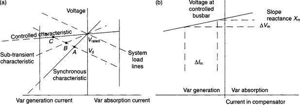
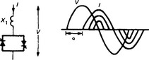
Figure 41.7(a) illustrates the voltage–current characteristics of a synchronous compensator. The rated excitation voltage corresponds to the rated voltage of the system. If the system voltage falls below its rated value to Vd and the field current remains unchanged, the var generation will initially follow the sub-transient characteristic to point B but it will finally settle to point A on the synchronous reactance characteristic. In practical applications of synchronous compensators, the machine excitation will usually be controlled either to maintain a nominally constant Mvar output or to maintain a nominally constant ‘target voltage’ on the system, subject to a defined ‘droop’, or slope characteristic. Thus, for 5% droop, and starting from the float condition with zero output, a reduction of 5% of terminal voltage will provoke an increase in excitation sufficient to generate rated leading current. Conversely, a voltage rise of about 2.5% will cause the synchronous compensator to absorb its rated lagging current. When there is a sudden disturbance, the output will initially follow the sub-transient characteristic as before, but after a few cycles the fast excitation control will cause the output to settle at the appropriate point C on the controlled characteristic. As shown in Figure 41.7(b) the slope of this characteristic is equivalent to a reactive impedance, Xm, such that a voltage change, ΔVm, at the controlled bus-bar will cause a reactive current change ΔIm in the synchronous compensator, i.e.
Synchronous compensators have several limiting or disadvantageous features; costs are relatively high and losses significant; they need good foundations, buildings, complex auxiliary systems and regular maintenance and refurbishment that detracts from availability. These drawbacks prompted the development of alternative types of equipment, using static components, with the synchronous compensator acting as the initial benchmark for dynamic response.
41.5.2 Sign convention for vars and reactive current
There are standard sign conventions for power and vars when current flows from a system bus-bar into a load. Power is positive for the component of current that is in phase with the voltage; vars are positive for a load operating at lagging power factor, i.e. when the current flowing into the load lags the voltage on the bus-bar. By this convention, when treated as loads as in Figure 41.7, shunt reactors will draw positive vars from the system, shunt capacitors will draw negative vars and generators will draw negative power. However, a reversed sign convention has been adopted to define the ratings of var compensation equipment for the following reason.
Generators supply both the power and the vars to satisfy the demands of the system and its loads. The sign convention for generators is that both power and vars are positive when current is flowing from the generator into the system bus-bar to supply a lagging power factor load. A synchronous compensator behaves in the same way as a generator operating at zero power and therefore it uses the same sign convention for vars. Thus, vars are positive when the synchronous compensator is over-excited, acting as a shunt capacitor and supplying an inductive (positive var) load and negative when it is under-excited, supplying a capacitive (negative var) load.
The same sign convention has become the norm for defining and specifying the var duties and output ratings of shunt static var plant and is thus consistent with that for rotating plant, i.e. shunt capacitive vars are designated as positive and shunt inductive vars are designated as negative. Note, however, that as shown in Figure 41.7, which treats the compensating plant as a load, the corresponding currents have opposite signs to those for vars.
41.5.3 Basic features of static compensation
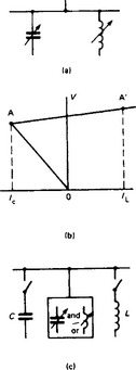
The main elements of the traditional type of static var compensator (SVC) are a capacitor to generate vars and an inductor to absorb vars. To provide operation in both the generation and absorption modes, both elements must be used; at least one of them must be rapidly variable, Figure 41.8(a), in order to replicate the dynamic characteristic of a synchronous compensator shown in Figure 41.7(b). A capacitor element cannot give a stepless variation: therefore, if a smooth continuous variation is needed over the whole range A-A′ in Figure 41.8(b), a capacitor bank having a rating to give at least the current IC must be connected and the variable element must be inductive, with a rating to give a current at least equal to IC + IL.
Although a SVC does not generate a real voltage, its dynamic voltage–current (V–I) characteristic enables it to be represented in studies of the system behaviour as if it were a synchronous compensator. The reference parameters for the SVC’s characteristic are a target voltage, Vref, equivalent to the excitation voltage of a synchronous compensator, and an equivalent slope reactance, X. The SVC inductive current, I, (or capacitive current if I is negative) at an actual system voltage, V, is given by the function
The equivalent machine can be controlled to generate and absorb vars over a defined range of system voltage variation, but has no inertia. At the limits of the linear range, the SVC representation is changed to that of a simple shunt capacitor or reactor, as appropriate.
In some system applications the SVC must be capable of operating under different system conditions at the extremes of its range (i.e. at A and A′), but it need not be capable of swinging in a continuous manner from one extreme to the other. Its ‘dynamic’ or ‘swing’ range, which is the range over which it can give a very fast response, may be only a proportion of its total range. In such a design the size of the variable element, which is the most expensive item in per unit of rating, can be reduced to deal only with the required swing; mechanically switchable L and/or C elements, Figure 41.8(c), can then be controlled automatically to adjust the position of the dynamic range within the total range. The overall cost of the SVC is then reduced. Sometimes the total range of a SVC is extended by using its control system to control the switching of shunt capacitors or reactors connected elsewhere in the substation.
The first commercial application of a SVC was in 1964. It used a self-saturated reactor to reduce the lamp flicker caused by an electric arc furnace. The first static var compensator for a transmission system was installed in 1967, followed by another in 1969: both used saturated reactors (SRs) as the continuously variable inductive component, the first was a d.c.-controlled transductor and the second a self-saturated reactor with harmonic-compensation and slope correction.
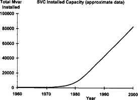
During the next decade many SVCs were commissioned, particularly on industrial systems where SVCs were installed to reduce voltage disturbances and to suppress disturbing lamp flicker caused by the var fluctuations of loads such as arc furnaces, large converter-fed drives in rolling mills and, in some cases, particle accelerators. The first thyristor-controlled reactor (TCR) for a transmission system entered service in 1978 and this coincided with a rapid growth in such applications of both thyristor and SR types of compensator, Figure 41.9. This growth resulted mainly from two factors. First, the rapid increase in the cost of power made utilities more conscious of the need to minimise transmission losses. Second, the growing opposition in industrialised countries to the construction of new transmission lines encouraged the maximisation of power transfer down existing rights of way. The 1990s saw the advent of a completely new type of static controller, the ‘STATCOM’, which uses voltage sourced converter technology.
41.5.4 Harmonic-compensated self-saturated reactor
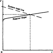
The saturated reactor (SR) is the original type of SVC; it gives an inherent variation of reactive current with voltage and its response does not depend on an imposed control system. The variable element comprises an iron-cored inductor whose core becomes saturated during each half cycle of the supply voltage and this core saturation results in a r.m.s. voltage–current characteristic as shown in Figure 41.10. This voltage–current characteristic resembles the controlled characteristic of a synchronous compensator. A saturated reactor can only absorb vars from the system but not generate vars; its saturation voltage is the ‘excitation voltage’ of an equivalent machine and its slope reactance is the ‘droop’. The operating current of the saturated reactor automatically adjusts itself to the point at which its characteristic intersects the system load line. If the terminal voltage falls below the saturation voltage, the SR current becomes negligibly small. Shunt capacitor banks are used to enable a SR type of SVC to generate vars.
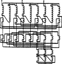
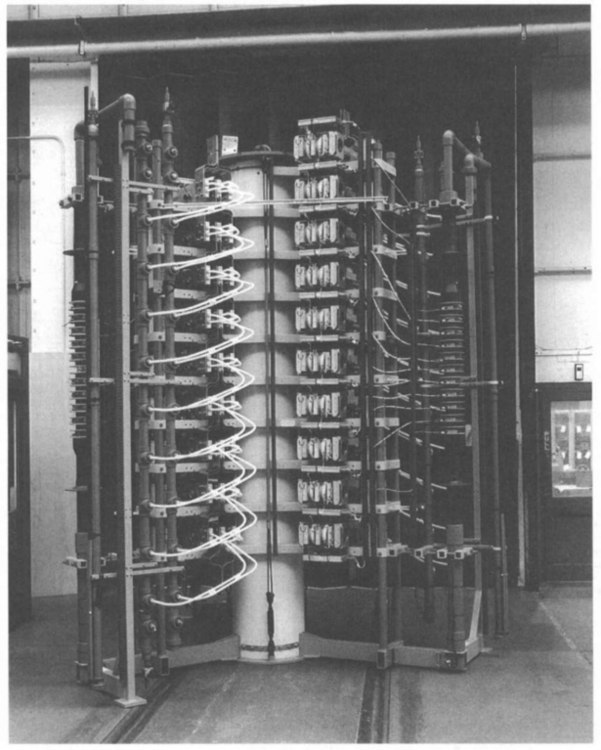
An iron-cored inductor with a simple winding is rarely used on a power network, as it generates large magnitudes of odd harmonic currents. However, by interconnecting sections of all three-phase windings it is possible to cancel out most of these harmonics in normal operation. The twin-tripler and treble-tripler harmonic compensated SRs (invented and developed by Dr E. Friedlander of the former General Electric Company, England) use this principle and have, respectively, six and nine active iron-cored limbs with inter-star connected windings and ratings up to 170 MVA for a treble-tripler saturated reactor, Figure 41.11. In addition to reducing the harmonic content of the reactor current to negligible proportions the designs give a voltage-current characteristic with a sharp knee point and a slope that remains linear to within about 1%, for currents from about 10% to more than 300% of rated load. The slope reactance is normally within the range 8–15% on the basis of nominal full-load rating.
41.5.5 Thyristor switches
In the 1960s, the demand for thyristors in industrial applications led to the very rapid development of devices with high withstand voltages and also capable of operating at high currents. Thyristor pairs with inverse-parallel connection Figure 41.12(a) are suitable for use as static switches, capable of extremely fast and frequent switching operation without the time delays, wear and tear and maintenance requirements of mechanical switchgear. A.c. thyristor switches were at the heart of most of the SVCs supplied during the 1980s and 1990s.
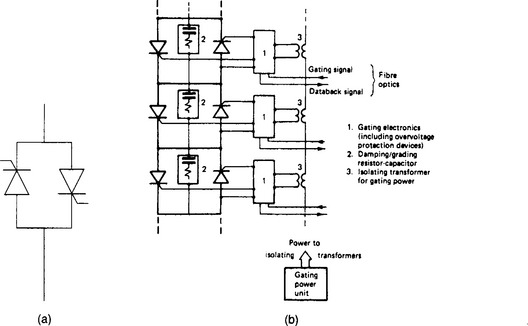
For a practical application, thyristors are assembled in a modular way into an ‘a.c. thyristor valve’. An a.c. valve is made up of inverse-parallel connected thyristors, which are themselves connected in series (and occasionally in parallel) to obtain the necessary rating, with voltages up to 40 kV and currents up to about 6kA. The cost of a thyristor valve is influenced not only by the ratings of the thyristors, but also by the number of voltage levels in series. Thyristors are available with voltage ratings up to about 8 kV (peak), although derating factors of 2 or more need to be applied in a series string of thyristors to determine the actual rms operating voltage of each thyristor.
Differences in the thyristor leakage currents, stray capacitances and stored charge all tend to cause an uneven voltage distribution between series-connected thyristors. A resistor–capacitor a.c. grading network is used in parallel with a d.c. grading resistor across each thyristor level, Figure 41.12(b). These grading networks reduce the voltage unbalance, and the R–C network also serves to damp the transient overshoots in the reverse voltage that occur when thyristors come out of conduction (twice per cycle per valve). Individual thyristor levels within a module are protected against overvoltage by breakover diodes or similar devices, which provide a gate pulse for forward firing of the thyristors above a pre-set overvoltage level. Special care must be taken in the design of the gating electronics and the signal transmission circuits to ensure coherent (simultaneous) firing of all the series-connected thyristors.
Most thyristor valves are indoor installations, with air insulation and water cooling. Only pure demineralised water having very high resistivity is allowed to flow through the thyristor heat sinks, which are at high voltage with respect to ground. The water cooling plant is mounted separately at ground potential and the pipework from ground to the thyristor stacks includes some sections made of insulating material. Air cooling is much simpler than water cooling, but it limits utilisation of the current capability of the thyristors and is rarely used for SVC applications. Figure 41.13 shows one type of thyristor valve used in a SVC installation in a transmission network.
The thyristor-controlled reactor (TCR) comprises an a.c. thyristor valve connected in series with a linear reactor. One phase of a TCR is shown in Figure 41.14. Variation of the current in the TCR is obtained by control of the thyristor conduction duration in each half-cycle, from a 90° firing angle delay (as measured from the applied voltage zero) for full conduction to 180° delay for no conduction.
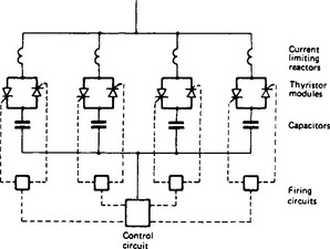
A.c. thyristor valves consisting of inverse-parallel connected thyristors, very similar to those used for the TCR, are used to enable rapid and frequent switching of blocks of capacitors, Figure 41.15. The thyristor-switched capacitor (TSC) gives directly the effect of a variable capacitance, although for reasons given below the variation is in steps.
Once gated, the thyristor valve will conduct for a half-period and unless again gated the current will then cease. A TSC, therefore, can only give a variation of capacitance between two states, on and off, for a discrete period of an integral number of half-periods. The kind of point-on-wave control used to give variable output with a TCR is not a practicable option for a TSC.
At the end of each half cycle of conduction, the capacitor current through the thyristor reaches zero; unless re-gating occurs the capacitor will remain charged at peak voltage while the supply voltage peaks in the opposite polarity after a half-period. This imposes a doubled voltage stress on the non-conducting thyristor, so that a TSC valve usually needs approximately twice the number of thyristors in series compared with a TCR valve of equivalent voltage. Ideally, gating is arranged to take place when the voltage across the thyristor is zero and the supply voltage is at its peak (i.e. dv/dt = 0); this results in a transient-free energisation. Except when continuous conduction is achieved by repetitive re-gating, such ideal switching conditions are rarely achieved, owing to mismatch between the capacitor voltage (which normally slowly loses its charge from its previous energisation) and the system voltage (which may have changed its value during the same interval).
The TSC control system is normally arranged to choose the gating instant that gives the minimum transient. Nevertheless, quite large transients occur during initial energisation of an uncharged capacitor and current limiting reactors must normally be installed to reduce the magnitude of the inrush current to a value within the thyristor capability. With the exception of these switching transients the TSC does not produce harmonics.
It is possible to arrange for a very rapid discharge of the capacitors after each period of conduction; this can reduce the voltage stress on the non-conducting thyristor and provide more consistent conditions for the next energisation. With a delta-connected three-phase TSC, current zero is reached sequentially in the three phases. By connecting a suitably designed three-phase transformer across the capacitors, most of the energy stored in the capacitors can be commutated back into the system, and into discharge resistors, by transformer action. Core saturation effects supplement this transformer action.
41.5.6 Convertor-based FACTS controllers
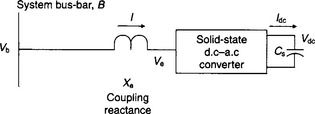
As described in Section 41.5.3, the behaviour of conventional SVCs is often represented by a model of an equivalent, but inertialess, machine incorporating an equivalent ‘excitation voltage’ and an equivalent ‘slope reactance’. However, there is a type of circuit, sometimes called a ‘synchronous voltage source’, in which a real alternating voltage, Ve, is produced from a d.c. source Cs by the process of inversion in a solid-state d.c. to a.c. converter; the a.c. voltage source is connected to a system bus-bar through a coupling reactance, Xe, Figure 41.16. The converter and its coupling reactance behave as an idealised rotating machine with an extremely fast response and, again, no physical inertia although there may be significant stored energy in some cases. The class of SVCs which uses this principle has been assigned the name STATCOM (a shortened form of STATic COMpensator).
The basic behaviour of a STATCOM is very similar to that of a synchronous compensator. If the voltage generated by the converter is less than the voltage of the system busbar to which it is connected, the STATCOM will act as an inductive load, drawing Mvar from the supply system. Conversely, a STATCOM will act as a shunt capacitor, generating Mvar into the supply system, when its generated voltage is higher than the system voltage. The rated inductive current and the rated capacitive current are usually equal, giving the STATCOM an almost symmetrical lagging and leading Mvar rating. This is very advantageous for some applications, but for those that require an asymmetrical MVar rating, it is usually economical to reduce the total STATCOM rating and to bias its output using conventional fixed or thyristor switched reactive elements.
The losses of the converter are normally supplied from the system, in the same way as for a machine, and not from the source of direct voltage or current. Nevertheless a STATCOM can exchange real power with the a.c. system if the d.c. source is arranged to supply or absorb the power that it is desired to exchange on the a.c. side.
41.5.6.2 Voltage-sourced converters
Various types of inverter circuit and source have been suggested and examined. D.c. voltage-sourced converters (VSCs) have received the most attention in the practical realisation of the STATCOM principle and can also be used in FACTS controllers connected in series with a transmission line or load.
The inverter may use either conventional thyristors with forced commutation, or devices that have been designed to be turned off as well as turned on, such as gate turn-off (GTO) thyristors; these devices have been used for many years in drives for traction and industrial applications. Other devices, for example the Integrated Gate Commutated Thyristor (IGCT) or the Insulated Gate Bipolar Transistor (IGBT), require less energy for the switching process and are available with ratings that can readily be used in some FACTS controllers.
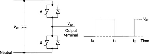
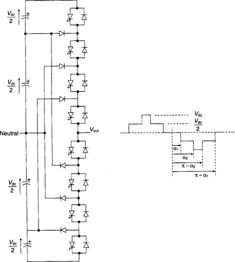
Figure 41.17 illustrates a basic single-phase inverter employing diodes and GTOs connected in inverse-parallel; the converter produces a square voltage waveform at the output terminal as it switches the direct voltage source on and off. This basic two level converter can be developed to produce various multi-level converters, such as the five level converter of Figure 41.18, for which the harmonic content is reduced and the voltage approximates more closely to a sine wave.
The direct voltage source can be a battery, whose output voltage is effectively constant and which has the capability to supply or absorb energy. For FACTS controllers a simple d.c. capacitor is usually used as the source; the d.c. terminal voltage can be raised or lowered by controlling the inverter in such a way as to increase or decrease the capacitor’s stored energy.
41.5.6.3 Three-phase converters
Three single-phase converters, for example of the type illustrated in Figure 41.17, can be connected, one per phase, to form a three-phase converter. The three single-phase converters can be controlled in a co-ordinated way to generate a balanced three-phase set of voltages. There is also freedom, under system fault conditions—or for compensating unbalanced loads—to control each phase independently, in order to assist in balancing the system while avoiding converter overload. When using independent capacitors for the d.c. voltage sources, the voltage in each phase can easily be changed independently of the other two phases if necessary.
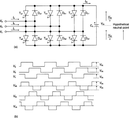
When the primary objective of the STATCOM is to respond to balanced load conditions, it is convenient to use the same d.c. source voltage for all three phases; the three converters can take the form of a Graetz bridge as shown in Figure 41.19(a). The three phase voltages are shown in Figure 41.19(b), with respect to the apparent neutral of the three-phase system. It will also be seen that the line-to-line voltages reach twice the peak magnitude of the phase voltages but for a shorter duration (120° conduction angle rather than 180°, due to the commutating action of the individual phases). This inherently eliminates third harmonic components from the line-to-line voltages under balanced system conditions, but during fault and unbalanced conditions, particular care is needed in the control and protection of the converters because of the use of a common d.c. source voltage.
41.5.6.4 Improving the voltage waveform
Clearly the basic square waveform is too distorted with low order harmonic components to be of practical application but can be improved by means of multi-pulse operation similar to that used for large rectifiers. Identical three-phase bridges (as in Figure 41.19(a)) can be connected to transformers that have phase-displaced outputs. Star- and delta-connected windings have a relative 30° phase shift and a converter bridge connected to each transformer would give 12-pulse operation and eliminate 5th and 7th harmonics from the line currents for balanced operating conditions. The transformers may be operated in parallel, in which case 5th and 7th harmonic currents will circulate between the converters, limited by the transformer reactance. Alternatively the transformers can be connected in series so that their respective 5th and 7th harmonic voltages will cancel out and so prevent any flow of the corresponding currents.
With four transformers having relative phase displacements of 15°, 24-pulse operation can be obtained; with eight transformers having 7.5° phase shift, 48-pulse operation results. It is usual to employ a simple transformer to provide the step-down duty from the high voltage system to an appropriate intermediate voltage; several different designs of phase-shifting transformers are then required to supply the individual converter bridges.
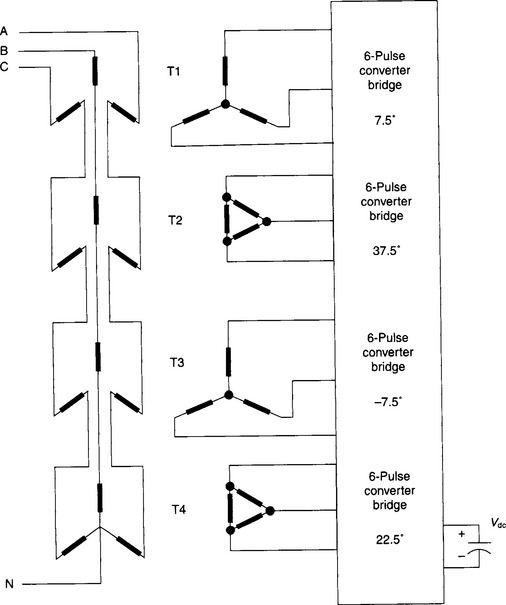
A simplified arrangement is illustrated in Figure 41.20. Two star–star and two star–delta transformers are connected with their primary windings in series and each secondary winding is connected to a 6-pulse bridge converter. All four of the converters utilise the same d.c. voltage source but they are operated effectively with relative phase-displacements of 15° to produce a quasi 24-pulse configuration. The 12-pulse harmonics which are characteristic for each pair of converters are not perfectly cancelled, but the residual magnitude is acceptably small. For practical applications of this kind of STATCOM, the Graetz bridges must use several GTOs in series in each leg of the bridge to obtain an adequate rating. The GTOs in each leg must be arranged to turn on and off at precisely the same instant (within microseconds) to ensure good voltage sharing between the individual GTOs.
41.5.6.5 Pulse width modulation
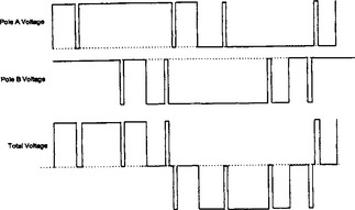
Pulse width modulation (PWM) is an alternative method of harmonic control. The power electronic switches are repetitively turned on and blocked several times during each half cycle. The sequential switching instants are selected in a co-ordinated manner, to satisfy simultaneous requirements, i.e. to develop the desired fundamental voltage and to eliminate selected low order harmonics. Figure 41.21 illustrates how two poles of a converter (such as that shown in Figure 41.17) can be controlled, each with 5 on/off actions per cycle, to eliminate both 5th and 7th harmonics together. Extra, correctly timed, switchings can eliminate additional higher harmonic components. IGBTs and IGCTs require much lower switching energy than GTOs and are better suited to applications that use PWM techniques. Multi-module arrangements are necessary to obtain high ratings.
41.5.6.6 Multi-level converters
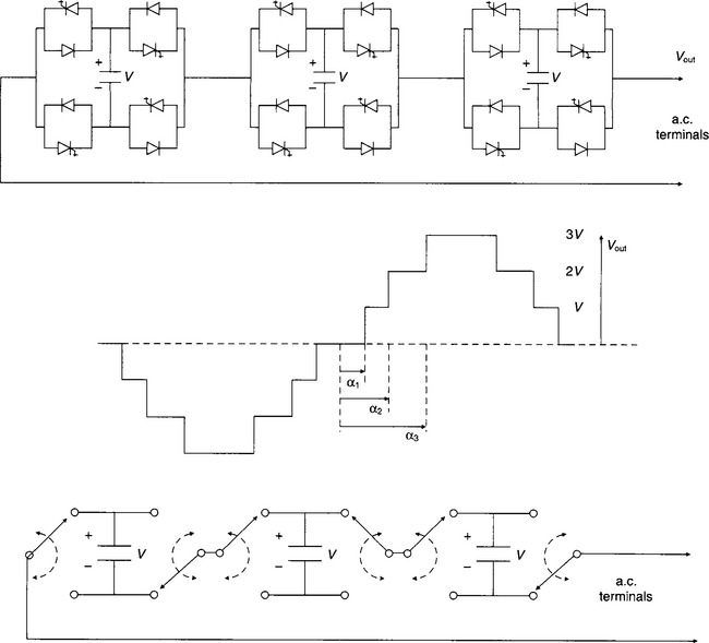
By combining sets of GTOs and their diodes in series, additional steps can be added to the output voltage waveform. Co-ordinated control of the switching instants of the series levels increases the controllability of the fundamental and harmonic content of the waveform. One important form of multi-level converter is the ‘chain circuit’ in which several converter bridges, each with its own source capacitor, are connected in series. By appropriate switching of the GTO and diode pairs, the d.c. sources are connected into the circuit with either positive or negative polarity or are bypassed to give zero voltage contribution.
This is illustrated in Figure 41.22 that shows that a single-phase chain with only three links can produce seven output levels. Each link in the chain produces its own rectangular block of voltage, with an amplitude equal to its own source voltage (normally all these source voltages are controlled to have the same value). Each voltage block therefore makes a contribution to the total fundamental voltage and to the total spectrum of harmonics. The more links there are in the chain, the more closely the overall waveshape approximates to a sinusoid. This stepped waveform appears broadly similar to the current waveform of a conventional multi-pulse a.c. to d.c. rectifier. However, the rectifier waveform consists of a series of pulses of varying height but equidistant in time, whereas for the chain circuit, the pulses are of equal height and the interval between switching instants varies. In principle there is no limit to the number of converter bridges (or ‘links’) that can be connected in series in a chain to generate, directly, a high value of alternating voltage with a small content of harmonic distortion.
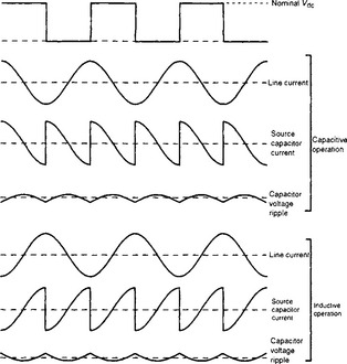
41.5.6.7 DC source voltage ripple
The d.c. source should preferably be strong enough for its voltage to remain effectively constant at the chosen level, under steady state conditions. In practice, especially for capacitor voltage sources, a compromise is necessary to allow the capacitor to charge and discharge to some extent between each switching operation, i.e. a constant average voltage is maintained but with a super-imposed ripple voltage of a few per cent, Figure 41.23. This ripple must be taken into account in selecting switching instants and in evaluating the overall harmonic behaviour of the converter system.
41.6 Shunt compensation
The load carried by a power system is continuously changing. Major variations in total load occur quite slowly, over a period of tens of minutes or longer in a daily cycle see Figure 41.24, which itself changes with a weekly and yearly variation. Normally any very rapid changes of load are only a small proportion of the total and do not affect the overall pattern.
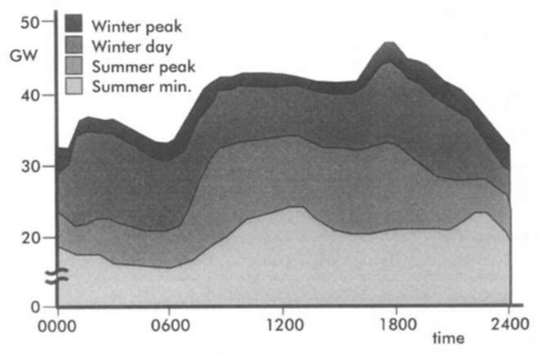
Figure 41.24
For a system operating under normal conditions the overall var compensation requirements also change relatively slowly. In a well-proportioned system the var flows are not sensitive to small load changes and it is generally possible to use fixed shunt reactors or capacitor banks to balance the vars for average load conditions. Often, however, it is advantageous to arrange that some or all of these shunt compensation elements are switchable, so as to give better control and to reduce unnecessary losses. These discretely variable devices are the simplest and the most common var compensators.
Many power systems now take advantage of the benefits offered by continuously variable var compensators. These can be used for particular categories of application such as:
(1) the compensation of rapidly varying loads that could otherwise cause unacceptable voltage disturbances on the power network;
(2) providing emergency voltage support in response to a circuit fault that increases the load current through each of the transmission lines that remains in service;
(3) giving continuous voltage control at a weak point of a network, where voltage variations due to normal load changes could otherwise become excessive and pose a threat of voltage instability;
(4) giving almost instantaneous overvoltage control in the event of a major load rejection on a long-distance transmission system;
(5) giving continuous fast control where transient stability is important, particularly on long-distance transmission; and
(6) on a tie line between two systems, damping out load swings which otherwise could lead to dynamic instability.
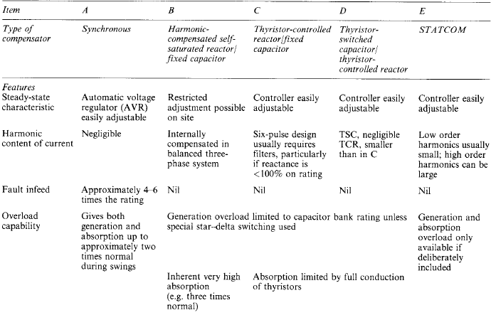
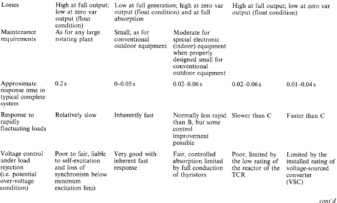
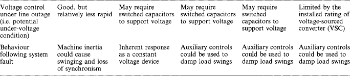
These different applications call for different characteristics of the variable var compensator. The types of compensator are reviewed in this section, with particular reference to their operating characteristics and applications, a comparative summary of which is given in Table 41.1.
41.6.2 Mechanically switched reactors and capacitors
Mechanically switched reactors and capacitors are used at all voltage levels, from the highest voltage transmission systems down to the correction of power factor on a works distribution system. Both technical and economic factors influence the decision to install switched reactive compensation. In many cases, operational considerations would permit the units to be permanently connected, but at the expense of continuous losses. The losses can be reduced by the installation of a switch suitable for fairly frequent operation, but this entails additional capital and maintenance costs.
If the compensation unit is permanently connected to other equipment (e.g. to a load or to a line), that equipment’s protective circuit-breaker will also serve for clearing faults in the compensation plant. In assessing the economics of var balance it is desirable to know for what proportion of the time a unit could be switched out, but this data is often difficult to obtain from the existing loading information and even more difficult to predict for the future.
41.6.2.1 Shunt reactors
In transmission systems with very long lines, shunt reactors are often installed at the ends of each line section to control its voltage under energisation and light-load conditions. During times of heavy loading, when the line var gain due to the shunt capacitance is offset by its series var loss, it becomes desirable to switch these reactors out. This helps both to increase transmission capability and to minimise system losses.
However, this requires transmission-voltage switches or circuit-breakers, which are expensive. Moreover, in the event of a large loss of load it would leave the system with a large excess of vars, leading possibly to excessively high voltage levels which could be unacceptable even for the short time necessary to reconnect the shunt reactors. As described later, a combination of fixed and continuously variable reactors may be a beneficial solution in these circumstances.
Where transmission or distribution systems include substantial lengths of cables, particularly at higher voltages, shunt reactors are sometimes installed at bulk supply points to compensate for the excess of vars under light-load conditions. To reduce the cost of losses inherent in all compensation devices, these are normally switched off as the load builds up.
41.6.2.2 Shunt capacitors
A very common and important application for shunt capacitor banks is in power factor correction (pfc) for industrial and commercial consumers. Here a straightforward economic evaluation is used to decide on the optimum reduction of var demand. The pfc capacitor banks usually consist of several separate units, or groups of units, each with its own contactor or switch. The load demand and power factor are, effectively, continuously measured and capacitor units are switched in and out as necessary to achieve the desired overall power factor for each successive tariff period, which may be only 15 or 30 min, for example.
Capacitor units have a very small inherent inductance and when units are switched back-to-back, without regard for the stored charges that each possesses at the instant of switching, there is a very large transient current flow between the units as the voltages are equalised. It is usual to limit the amplitude of the transient current by adding very small inductors into the circuit of each capacitor unit. These inductors may reduce the natural frequency of the capacitor circuits to perhaps 1 or 2 kHz. However, the installation of a pfc bank may result in a resonance between its capacitance and the system reactance at a prevalent low order harmonic, e.g. fifth or seventh; the switching inductors will not have a significant effect at such frequencies. Resonances of this kind can cause possible overvoltages or excessive currents. The capacitor bank may (because of its very low impedance at harmonic frequencies) act as a sink for harmonic currents produced by pre-existing voltage distortion in the network, and so become overloaded by them unless suitable series reactors are included. Before installing power factor correction banks and their associated series reactors, measurements or estimates of pre-existing harmonic voltages in the network should be made and the effects of the capacitors on the remainder of the system should be studied.
In some networks it is the practice to install shunt capacitor banks at critical points of distribution systems with long overhead feeders, such as those supplying rural areas; the capacitors at the substations are usually switchable, whereas those part-way down the feeders are often pole-mounted and permanently connected. In the UK, owing partly to tariff incentives, load power factors tend to be high and there is no general application of this type of shunt capacitor compensation.
In the UK, power is delivered to distribution companies at bulk supply points, usually at 132 kV. Switched shunt capacitors are connected at some of these bulk supply points and are often used to compensate for var imbalance on the transmission network in addition to the var demand of the l.v. connected loads. Bank ratings are generally 60 Mvar and several are installed at some substations. In the last few years there has been an interesting development, resulting in the connection of switched capacitor banks of 150 Mvar and 225 Mvar directly on the 275 kV and 400 kV systems. In order to eliminate any possibility of adverse consequences due to amplification of pre-existing harmonic distortion, these banks are arranged as selectively damped harmonic filters, with very low losses at the rated power frequency but strong damping of any third harmonic currents.
41.6.2.3 Technical aspects of switching reactors and capacitors
Any switchgear installed to control a shunt capacitor bank or a reactor, be it circuit-breaker or load switch, must be carefully chosen, as the switching duties, even though the load currents are normally small, are not easy. The number of operations is often high.
With reactor switching, de-energisation may present difficulties if the current does not decrease smoothly to zero as the switch contacts separate and the arc is quenched. If there is current chopping and the current collapses to zero almost instantaneously, even from a very small current, the high rate of change of current can generate extremely high voltages across the reactor. In order to avoid damage to the reactor, the circuit-breaker and other equipment, it is necessary to ensure either that overvoltages cannot be generated, or that they are limited to levels which do not surpass the insulation withstand levels of the system, for example, by means of surge arresters.
When capacitors are energised, high transient inrush currents are produced which may severely stress both the switch and the capacitor. Circuit-breakers, or switches, that are designed to provide point-on-wave switching for each phase are able to reduce these inrush transients to very much lower magnitudes.
De-energisation is also a severe duty for any switch because the interruption process leaves the capacitor charged to the peak value of the system voltage. Within a half-cycle of the instant of interruption, the polarity of the system voltage will have reversed and the voltage across the opening contacts of the switch will be twice the normal crest voltage of the system. If the insulating medium does not recover sufficient dielectric strength, the arc re-strikes and there is a short pulse of current, which leaves an even higher level of voltage trapped on the capacitor (with reversed polarity). In the worst case, this process continues until there is a failure of major insulation on the capacitor or other equipment. Special tests are conducted on switchgear intended for capacitor switching to validate its suitability for the purpose. In some cases special discharge circuits are connected into the capacitor circuit to ensure that the capacitor voltage decays very rapidly after the current is interrupted and that, even if arc re-ignition occurs, there is no magnification of voltage.
41.6.3 Synchronous compensators
The synchronous compensator has a more positive action than most types of compensator in supporting a weak system, as it has both a generated voltage and inertia that enable it to act transiently as if it were coupled to a prime mover. The synchronous compensator can maintain full rated current independent of its terminal voltage and may be arranged to increase its var output temporarily to provide transient assistance to the system. This has been of value in certain applications; for example, where power is supplied by h.v.d.c. to a system having minimal generation, the receiving system has usually been strengthened by a synchronous compensator.
When synchronous compensators have been used for dynamic compensation of high voltage systems it has been necessary either to provide a dedicated transformer or, in some cases, to utilise a tertiary winding on a transformer which links two voltage levels within a system. With tertiary connection, the inter-winding reactance distribution of the transformer determines the high voltage bus-bar to which the compensator is most closely coupled.
The main limitations of synchronous compensators compared with static alternatives are a notably slower speed of response, typically 0.2 s, higher losses, inertia that can cause underdamped oscillations or loss of stability in some transient conditions, higher maintenance requirements (and lower availability) and higher capital costs. Because of their inherent limitations, synchronous compensators have now been almost completely superseded by static controllers.
41.6.4 Static var compensators
Saturated reactors are normally used in conjunction with shunt capacitor banks to provide var generation as well as absorption. Some of the shunt capacitors are configured as harmonic filters that are permanently connected in parallel with the SR; other shunt capacitor banks may be permanently connected or switched, as appropriate to the duty of the SVC.
A significant feature of the SR type of SVC is that, because of its transformer-like construction, the SR has very low maintenance/operational requirements and also a high short-time-rated overload capability of up to 4–5 times rated load for 1 second, or longer if necessary. This can be of use in networks with long transmission lines, where the Ferranti effect following a loss of load can produce excessively high temporary overvoltages. The SR, by swinging rapidly into a high var absorption mode, can balance the var production of the line and so reduce the inherent overvoltage.
The SR is normally operated as a fixed-voltage device, though adjustment of its saturation voltage over a range of a few per cent is possible in principle. If it is to be connected to a system whose voltage level must be adjustable, then a regulating transformer is normally connected between the SR and the system bus-bars, Figure 41.25. Where a step-up transformer is necessary to match the SR voltage (normally 6–69 kV) to the system voltage, this can include an on-load tap-changer to provide any regulation that is needed.
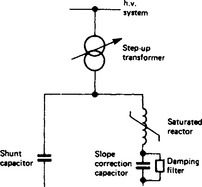
The V–I slope typically required at the terminals of a SVC for transmission applications is around 3–5%, whereas the total slope obtained from a SR plus step-up transformer may be 15–25%. To compensate for this difference, a slope-correcting capacitor is connected in series with the SR as shown in Figure 41.25. To avoid the possibility of sub-harmonic oscillations after energisation, a damping filter is fitted across this capacitor.
The current drawn by a SR depends directly on the time-integral of the voltage applied to its terminals and its speed of response is therefore extremely fast, responding to voltage changes within the same half-cycle. Owing to the polyphase construction and the interconnection of its windings, a SR operates in a manner different from that in a linear shunt reactor. The latter absorbs the capacitive energy of the system as electromagnetic energy and returns it all every half-cycle, phase by phase. In contrast, the treble-tripler reactor, by virtue of its nine-active cores and interconnected windings, transfers about 90% of its energy from phase to phase as the magnetic flux commutates from one core to the next every 1.1 ms at 50 Hz (2 × 9 = 18 transitions per period). The inclusion of the slope-correcting capacitor slightly slows the effective overall response and a slope-corrected treble-tripler reactor SVC responds effectively to a step change within one to two cycles, dependent on the system impedance and on the rating of its sub-harmonic damping circuit. An alternative method of achieving the slope-correction effect without time delays has been used for lamp flicker compensation in Figure 41.46(b).
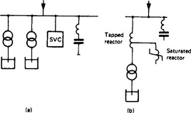
41.6.4.2 Thyristor-controlled reactors
The simplest design of TCR, Figure 41.26(a), uses three single-phase valves, usually connected in delta, giving a six-pulse unit: hence, it produces appreciable levels of fifth and seventh harmonic currents and in most cases will require the use of harmonic filters. Shunt capacitors are needed to provide var generation and, for large SVCs, it is usual for some of these banks to be thyristor switched. Although for some ratings it may be possible to connect the TCR directly to the power system bus-bar, for most applications an interconnecting transformer is required to match the optimised valve voltage to the system voltage; on-load tap-changers are very rarely included.
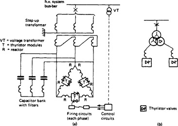
A few installations have used a step-up transformer with two phase-displaced secondary windings connected star and delta, each with a delta-connected set of thyristor valves and reactors, Figure 41.26(b). This 12-pulse design gives better harmonic compensation, the principal harmonics being now the 11th and 13th, and simpler filtering can be used.
The control system of a TCR can produce any desired voltage-current characteristic derived from various input signals. A basic characteristic for a transmission compensator having a closed-loop voltage control, with current compounding, is shown in Figure 41.27. When the valve reaches maximum conduction, the characteristic follows the slope set by the impedance value of the linear reactors plus coupling transformer (typically 0.7–1.0 p.u. on the basis of full load rating) up to the point of the thyristor current thermal limit, when by phasing back the firing angle the current is held constant up to the maximum voltage limit of the thyristors. The actual relative positions of these constant-current and continuous-conduction parts of the characteristic may be changed to suit the design requirements.
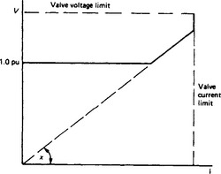
A speed of response to small disturbances of 1 to 3 periods is achievable with this type of control system. A slightly faster response may be obtained by using an open-loop current control; this can be useful for certain industrial applications where the highest speed is required and some sacrifice of control accuracy can be tolerated.
41.6.4.3 Thyristor-switched capacitors
Thyristors can be used to switch on a large bank of capacitors faster than is possible with a mechanical switch; therefore a potential application of a TSC is for fast boosting of a transmission-line voltage to maintain system stability. A TSC, perhaps having several steps, as in Figure 41.15, could also be used on its own to provide swing damping in a transmission system.
TSCs are commonly used in conjunction with TCRs to give much reduced losses at zero var output (float condition) compared with the losses of a scheme using a fixed capacitor and a larger TCR; they are also used to provide an increased operating range in the var generation region where speed of capacitor energisation is of importance and a high frequency of operation is required. In these applications the TSC provides the coarse steps, seldom exceeding four, whereas the TCR gives a fine continuous control in between.
In order to obtain a fine control of output using only TSCs, there must be a series of small steps, each with its own capacitor bank and thyristor switch. The number of steps and hence the fineness of control are dictated by economics in the cost of separate valves for each step and the complexity of controls. TSCs have occasionally been used for power-factor control of loads with frequently varying var demand; here the capacitor banks and thyristor valves were at a low voltage and a large number were used in parallel to approximate to a stepless control.
In the last decade, it has been found necessary to provide increased capacitive support for the National Grid in the UK. Because network requirements can change substantially over periods of a very few years, it is also desirable to be able to relocate equipment quickly to an alternative location. It is rarely possible to arrange for a high voltage connection to be quickly available, but transformers with 13 kV, 60 MVA tertiary windings are commonly available in Grid substations. The h.v. system may be either 400 kV or 275 kV and the l.v. may be 275 kV. 132 kV or 66 kV. Relocatable SVCs (RSVC) were specified, for connection to tertiary windings, and these only needed to provide capacitive Mvar; stepwise control of the output was permissible.
The specification for the RSVCs lent itself to an arrangement consisting of three TSCs, with binary ratings of 8.6, 17.1 and 34.3 Mvar, which are controlled in a co-ordinated way to provide the 60 Mvar output in seven steps of 8.6 Mvar, Figure 41.28. Twelve such RSVCs have been installed, in seven substations.
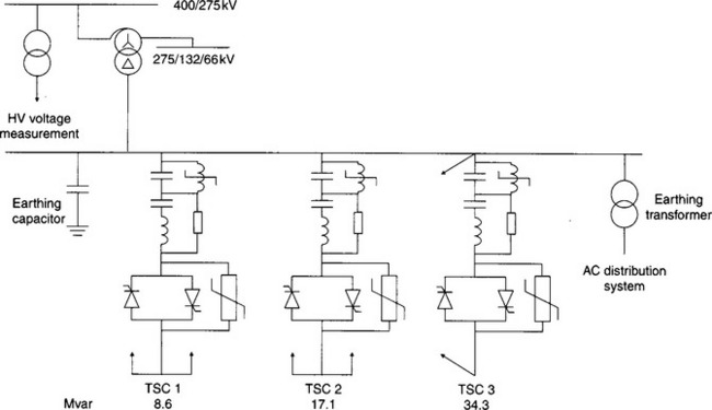
The ability of TSCs to reduce voltage fluctuations is very limited compared with that of other types of SVC and they cannot be controlled fast enough to be effective in reducing lamp flicker caused by arc furnaces.
41.6.5 STATCOM
41.6.5.1 Some practical implications
It would clearly be inappropriate to connect a voltage-sourced converter directly to the supply system, which will generally have a very much higher short-circuit power than the rating of the converter. As shown in Figure 41.16, there is normally coupling reactance between the system bus-bar and the converter terminals. When the converter is connected to the system via a transformer, this may provide sufficient inherent coupling reactance for satisfactory operation of the STATCOM.
In some applications where there is a stringent harmonic performance requirement, it may be necessary to include shunt capacitors or harmonic filters on the converter busbar, in which case buffer reactors (separate from the step-down transformer) may be needed to limit the flow of harmonic currents from the converter into the capacitors.
As well as limiting harmonic currents, the coupling reactance limits fault currents into the STATCOM; it also ‘softens’ the transient current response from the STATCOM when there is a fault on the supply system which collapses the voltage, or when there is a large magnitude dynamic overvoltage. Inevitably, the presence of the coupling reactance requires the voltage generated by the converter to be higher than that of the system when the STATCOM is acting as a capacitor and to be lower than the system voltage when the STATCOM is acting as an inductor. The vars absorbed by the coupling reactance (and the supply transformers) must be taken into account in the design and rating of the converters.
41.6.5.2 STATCOM operating characteristics
The ‘natural’ voltage–current characteristic at the terminals of a STATCOM, Figure 41.29(a), is entirely dependent on the converter source voltage Ve and on the coupling reactance, Xe, see Figure 41.16. In general the coupling reactance has a typical value between 10% and 20%, i.e. the voltage drop (or rise) across it is about 10 to 20% of the nominal system voltage at the rated current of the STATCOM. The continuous current rating of a GTO, 1GBT or IGCT is almost independent of whether the current lags or leads the voltage. These devices usually also possess a short-time, or transient, overcurrent rating, which may exceed the safe turn-off (or turn-on) current for the STATCOM valve components. If, by accident or design, the safe turn-off current is exceeded, then turn-off signals must be prevented from being issued until the current returns to below the safe switching level.
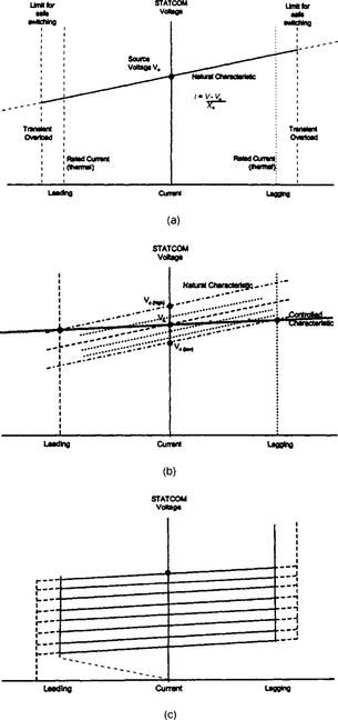
Figure 41.29 (a) Natural V–I characteristic of a STATCOM, (b) controlled V–I characteristic of a STATCOM; (c) family of V–I characteristics for a STATCOM
The nominal maximum steady state voltage for a supply system is 1.1 p.u. of its nominal value and this presents no difficulties for the design and rating of a STATCOM. However, a STATCOM must also withstand dynamic overvoltages and transient overvoltages up to the protective level provided by the STATCOM’s surge arresters. During transient conditions in which the instantaneous applied voltage exceeds the d.c. source voltage, the diodes of the STATCOM will allow current to flow, and this current will charge the d.c. source capacitors to a higher voltage.
For most practical applications, a SVC needs to operate with a slope reactance typically of between 2% and 5%, which is much lower than the value of the coupling reactance. Because the coupling reactance is fixed, the converter source voltage must therefore be changed as shown in Figure 41.29(b), raising it to obtain the desired loading (capacitive) current conditions or reducing if for lagging (inductive) conditions. This can be done very quickly, initially by changing the switching pattern and then followed, if appropriate, by changing the magnitude of the d.c. source voltage. The desired control characteristic is thus achieved by changing the source voltage in precisely the same way as for a synchronous compensator, but very much faster.
Both target voltage and slope reactance can be set in the STATCOM control. A set of voltage–current characteristics, for a range of target voltage settings with constant slope, is shown in Figure 41.29(c). For comparison, the V–I characteristics of a conventional SVC are shown in Figure 41.30. At reduced voltage, the STATCOM can continue to be operated at rated leading (or lagging) current, with a constant transient overload current margin. These capabilities are available down to very low voltages. In contrast, the current limits for conventional SVCs are proportional to voltage. A STATCOM is better able to provide reactive/current support for a supply system whose voltage is severely depressed, whereas a conventional SVC can generally do more than a STATCOM to limit dynamic overvoltage.
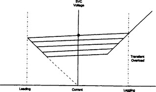
41.6.5.3 Transient response
Because the operation of a STATCOM is based on the generation of a sinusoidal voltage, its response to transient disturbances is inherently good and extremely rapid. Figure 41.31 illustrates how a STATCOM responds to a voltage disturbance. Prior to the voltage dip, the STATCOM is operating at about its rated lagging current. A dip of system voltage suddenly occurs, to about 50% of its steady state value. The STATCOM inherently responds to this disturbance by generating a capacitive current to support the system voltage but, even on the natural characteristic, there would be a capacitive overload current. To prevent this, the STATCOM control system detects the sudden change and reduces the target voltage to limit the STATCOM current to its rated capacitive value.
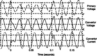
When the fault is cleared and the system voltage recovers to its pre-fault value, this will tend to cause an inductive overload current in the STATCOM. Again, the STATCOM control system is able to detect the change and adjust the target voltage appropriately. Although there is unavoidable transient distortion of the STATCOM current at each step change it can be seen that the changes from inductive to capacitive and capacitive to inductive current take place within a half cycle.
41.6.5.4 STATCOM losses
The forward voltage drop of GTO thyristors is greater than that of conventional thyristors because of the more complex system of semi-conducting junctions and the energy required for the turn-off duty. Figure 41.32 shows the approximate variation of STATCOM losses (% of rated current) through the operating range from rated leading to rated lagging current.
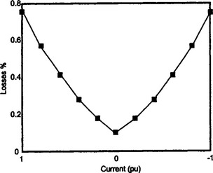
In many cases, the STATCOM output will need to be biased—generally towards the capacitive side for SVC applications. Figure 41.33 shows the loss patterns for an output range +1.0 to −0.5 p.u. current.
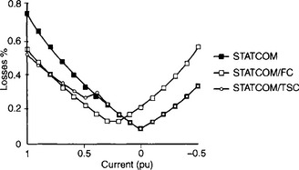
If the STATCOM is rated for an output of ±1.0 p.u. current, but the upper half of the inductive range is not used, then the losses in the float condition (0 Mvar) and within the lagging range are quite low, but become quite high in the upper part of the capacitive range. These capacitive losses can be reduced by halving the rating of the STATCOM and combining it with a TSC of about 0.6 p.u. to reduce the losses (and generally also the overall costs).
An intermediate option is also illustrated with a STATCOM of ±0.75 rating, to cover the total dynamic range, biased by a fixed capacitor (or filter bank) of 0.25 p.u. output. This may give a better overall optimisation of cost and losses especially if the predominant range of operation of the compensator is in the typical range from about 0.1–0.6 p.u. capacitive current.
41.6.5.5 Other types of STATCOM source
In addition to voltage sources using batteries and capacitors, STATCOMs can be operated with an inductor, which provides a source of direct current rather than voltage. A three-phase, current-sourced converter then generates a set of three-phase output currents which, by appropriate switching action, lag or lead the system voltages. The basic output current is a square or block wave and harmonic reduction requires PWM, or multi-level or multi-pulse techniques, and/or harmonic filters. The output current magnitude may be controlled by diverting part of the source current through a bypass circuit. The energy in the current source can be sustained by drawing energy from the supply system or by using an external energy source. However the losses of a current-sourced converter tend to be higher than those of a voltage-sourced converter.
41.6.6 STATCOM applications
41.6.6.1 Transmission applications
In order to demonstrate the features of STATCOMs and to gain practical operating experience, several prototype STATCOM installations were put into service in transmission networks. In addition, several smaller STATCOM installations have been used (particularly in Japan) to reduce flicker caused by electric arc melting furnaces. However, many of the conventional applications of SVCs do not need to take advantage of many of the particular features of STATCOMs, such as equality of lagging and leading outputs, faster response time, possible active harmonic filtering capability and smaller site area.
Nevertheless, confidence in the STATCOM principle has grown sufficiently for several utilities to adopt them for normal commercial service. As an example, in 1996, the National Grid Company plc of England invited tenders for relocatable dynamic reactive compensation equipment for its 400 kV transmission network, capable of generating 0–225 Mvar at 0.95 p.u. system voltage. A particular requirement was the inclusion of a STATCOM of 150 Mvar range. The design adopted includes a ±75 Mvar STATCOM in conjunction with a 127 Mvar TSC and 23 Mvar fixed capacitor to provide a full controlled range of output +225 to −52 Mvar, Figure 41.34.
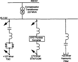
This STATCOM design is required to meet stringent harmonic emission levels and immunity to existing and future prospective harmonic levels. It uses multi-level converters in a chain circuit configuration. Typical voltage waveshapes are shown in Figure 41.35. The control system incorporates voltage control, reactive setpoint regulation, and a co-ordinating control for the STATCOM and the associated TSC. Provision is also made to include power oscillation damping control in the future, if it should be necessary.
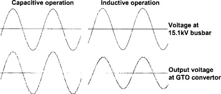
All the controls and power electronic equipment are housed in weatherproof, transportable GRP (glass reinforced plastic) cabins and the outdoor components are grouped together on frameworks to satisfy the requirement for easy relocation to another substation when this is required.
41.6.6.2 Specialised applications
Other applications of smaller STATCOMs, in service or under consideration, are for the reduction of lamp flicker due to arc furnaces, for voltage and var control for windfarms and for balancing of single-phase traction loads. These smaller units generally use PWM to obtain a satisfactory harmonic performance.
41.6.6.3 Energy storage applications
Some manufacturing processes require absolute continuity of supply to maintain product quality and/or safety, for example, float glass, paper, semi-conductor devices, and some chemical and nuclear processes. The cost of disruption may be so great that auxiliary or emergency power sources are economically justified. Uninterruptible Power Supplies (UPS) of moderate ratings are now very widely used to enable some processes to ride through brief voltage dips and interruptions. Where larger power ratings are required, STATCOMs, with enhanced energy storage or auxiliary power sources, offer a potential solution.
Batteries have already been mentioned as voltage sources, but for stored energies of many megawatt seconds, present designs of battery are bulky and expensive. Very large capacitor banks might be used but are not efficient for bulk energy storage. Super-conducting magnetic energy storage sources (SMES), together with current-sourced converters have also been used in prototype format (Figure 41.36) and, in the future, might be very suitable for energy storage. A very attractive energy source of the future is the fuel cell.
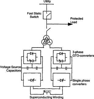
41.7 Series compensation
Series compensation may consist of capacitor banks with a single fixed value, or adjustable in steps, capacitors with one or more stages that are continuously variable or it may be provided by a synchronous voltage source. All equipment that is intended for series connection must have suitable insulation to ground and be designed and rated for or protected against faults that can cause severe overcurrents through it.
41.7.1 Series capacitor compensation
Series capacitors have, for many years, provided the only practicable means of compensating the series inductance of transmission lines. Nevertheless, the application of series capacitors in large power systems requires caution at the system design stage, because series capacitors always introduce natural frequencies below the power frequency. Series capacitors resonate with the generator and line inductances at subharmonic frequencies and the subharmonic oscillations which follow any transient disturbances can lead to self-excitation of generators, to rotor hunting and to shaft oscillations. The possible danger of this phenomenon was illustrated in the early 1970s when the shaft of a large turbo-generator was twice damaged in service, owing to subsynchronous resonance (SSR) excited by series capacitors in the transmission system.
The SSR phenomenon is now well understood as being due to near coincidence of a shaft torsional resonance frequency and the complement of an electrical subharmonic frequency. It can be fully analysed using non-linear differential equations of the complete electrical–mechanical system. For studying such phenomena more economically, however, digital computer programs have been developed, based on either eigenvalue analysis or frequency-response analysis of the complete system of linearised machine and network equations, including any shaft torsional equations of the turbine prime movers.
41.7.1.1 Subsynchronous/subharmonic resonance damping
Methods of damping subsynchronous oscillations include the use of SVCs, damping filters, dynamic control of the series capacitor impedance and generator excitation control signals. The awareness of the possible danger of SSR, the improved methods of study and the available methods of damping such oscillations have enabled the application of series capacitors to continue successfully, albeit with some constraints.
Subharmonic oscillation phenomena may also occur when capacitors are in series with devices that have a nonlinear reactive characteristic because they use saturable iron in the magnetic path, for example transformers, gapped-core ‘linear’ reactors and self-saturated reactors. These phenomena are amenable to non-linear or linearised analysis, but generally with only limited accuracy. Model studies using transient network analysers or simulators are employed in assessing individual applications involving transformers or linear reactors. Theoretical analysis of ferroresonance phenomena has not resulted in generally applicable conclusions. The performance of harmonic-compensated saturated reactors with slope-correcting series capacitors can be analysed satisfactorily and appropriate subharmonic damping filters can be designed accurately.
41.7.2 Controllable series compensation
41.7.2.1 Thyristor switched series capacitor (TSSC)
In a practical installation of series capacitors it is common for the overall bank to consist of several sections, each with its own protection, isolation and bypass switchgear. This subdivision provides an improvement in availability and more flexible adaptation to changing circumstances, including the possibility to avoid using capacitance values that would give undesirable resonance frequencies under particular system conditions.
It is impossible to obtain rapid or frequent bypassing and re-insertion of capacitor sections using conventional mechanically operated switchgear, but faster switching can be achieved using thyristor switches for one or more sections, Figure 41.37(a). There is a large discharge current when a capacitor is bypassed and a current limiting reactor (not shown) is needed to reduce the current to within the transient rating of the thyristor switch. Changing the capacitance value in discrete steps is suitable only for de-tuning SSR conditions but is not a satisfactory method of applying positive damping for SSR oscillations.
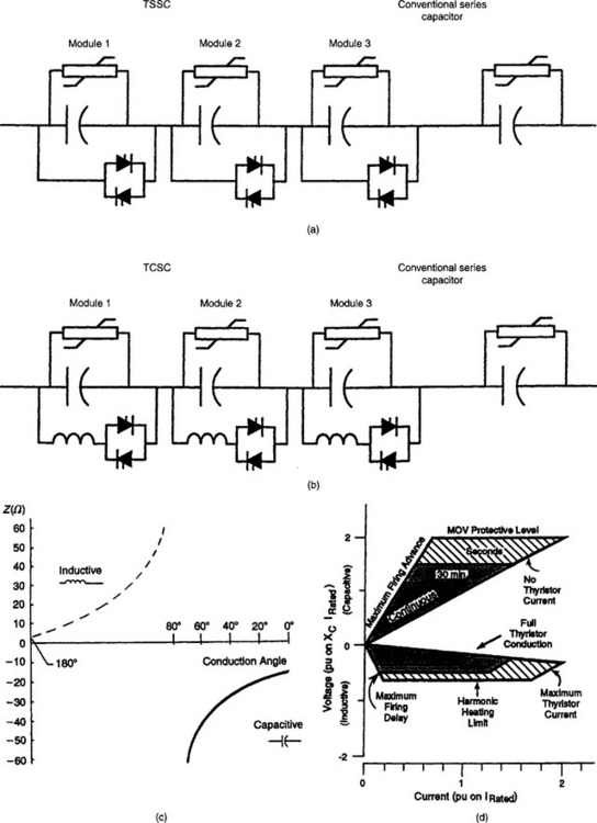
41.7.2.2 Thyristor controlled series capacitor (TCSC)
The TCSC is similar to the TSSC but the thyristor switch is converted into a TCR, Figure 41.37(b). By using point-on-wave switching of the reactor, two ranges of continuously variable impedance can be obtained, Figure 41.37(c). The controlled reactor has a significantly lower impedance than the capacitor so that when the thyristor valve is fully conducting, the overall impedance of the capacitor section becomes inductive; the current through the reactor is greater than the line current and the capacitor current is smaller. At the other extreme, when the thyristor valve is blocked, the line current flows only through the capacitor.
At some intermediate level of valve conduction, the effective inductive impedance of the reactor would be equal to the capacitor impedance and the combination would form a blocking circuit, with a very large voltage across it. Obviously, this condition must be avoided. Nevertheless, a range of satisfactory operating conditions can be obtained near to minimum conduction, giving the continuously variable capacitive effect that is desired from this circuit. There is another operating range near to continuous conduction, with a continuously variable inductance effect, but this is generally unimportant. Figure 41.37(d) illustrates the continuous and short-term capabilities of a single section of a TCSC.
Several TCSCs have now been installed in transmission systems. They can be controlled to apply positive damping to SSR conditions, if these arise.
41.7.2.3 Static synchronous series compensator (SSSC)
The advantages of series capacitors could be obtained and the major disadvantages could be avoided by using a FACTS controller to behave as a true negative inductance (i.e. with a reactance equal to −jωL instead of JωL). This can be done by means of a voltage-sourced converter, as described in Section 41.5.6.2, and controlling it so that the voltage across it lags the current through it by 90°, Figure 41.38. This gives negative inductance, not only at the system frequency, but also at lower frequencies and for the more important of the low order harmonic frequencies.
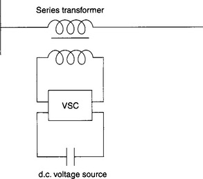
If the d.c. source is only a voltage but not an energy source, the voltage across the controller will only deviate from 90° by an amount sufficient to supply the losses of the controller itself. The controller will cancel out part of the inductance of the line, reducing the voltage across the line and reducing the apparent surge impedance. The stability limit for the line will be increased and a greater power may be transmitted—or a longer line may be used at the same power level.
Other control functions could be used in response to a variety of system and network conditions and contingencies. The control could be used, for example, to prevent the line being overloaded by acting as a variable positive inductance. It could be used as a fixed voltage source to drive a circulating current around a particular part of the network in order to avoid overload in another circuit. With an energy source, other methods become possible for controlling power flow in the line. If the energy source is a shunt connected FACTS controller, the combination is called a universal power flow controller (UPFC) and is described in Section 41.8.2. The interline power flow controller (IPFC) uses another series connected FACTS controller, in a parallel line, as the energy source, as described below, Figure 41.39.
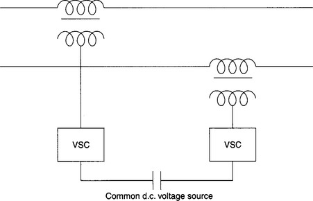
41.7.2.4 Interline power flow controller (IPFC)
It is not uncommon for two lines, that are of similar construction and rating, to follow different routes between major substations and so to have different lengths and different impedances. The sharing of current will be unequal. Furthermore, one or both circuits may link into additional load centres en route, with the result that one circuit becomes overloaded while the other has plenty of spare capacity. In such a situation an IPFC could be a far simpler and less disruptive solution than upgrading the overloaded circuit. It is very important in this application that the phase angle of the injected voltage should force sharing of the in-phase as well as the quadrature components of current in the circuits which are being equalised.
41.7.3 Buffering of loads from system disturbances
There are many industries and industrial processes that are intolerant to voltage dips and even brief interruptions. If critical drive motors are shut down because the voltage falls below about 85% of rated voltage, or inverters suffer commutation failures because of voltage dips or distortion in one phase, the disruption can result in a serious loss of production. There may be an extended shut down of the plant while the rescue and re-start processes are undertaken. A device that sustains the voltage on the load bus-bar in the face of disturbances on the system has great potential value for protecting the sensitive loads.
41.7.3.1 Short-circuit limiting coupling (SLC)
One system employed in the 70s was the short-circuit limiting coupling (SLC, sometimes also called the ‘resonant link’). The main elements were a series capacitor and reactor, of approximately equal ohmic values, connected between the consumer’s bus-bar and the utility bus-bar. If a fault, or a major disturbance, occurred in the utility system, auxiliary components automatically changed the capacitor impedance and converted the link to a large magnitude inductive impedance. This buffered the customer’s bus-bar from the effects of system faults and the critical plant continued to be supplied, without experiencing a disturbance, from customer’s in-house generating plant. The design and implementation of the SLC included measures to guard against SSR effects between the series capacitor and the local generating plant.
41.73.2 Dynamic voltage restorer (DVR)
The advent of voltage-sourced converter technology has enabled another buffering technique to be applied, which avoids the disadvantages of series capacitors and does not rely on local generation being present, the Dynamic Voltage Restorer (DVR), Figure 41.40. This can be designed to be effective for voltage dips down to about 50% of rated voltage, which is sufficient for most dips caused by lightning. Energy to maintain the level of the source voltage is usually derived from a simple rectifier on the input side. In order to deal with larger, prolonged voltage dips, it would be necessary to use an energy source of sufficient capacity to supply the load demand for the duration of the voltage dip.
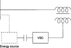
41.8 Controllers with shunt and series components
It was shown in Section 41.3.5 that the power flow through a simple transmission line is given by
Although this power flow is dependent on the voltages at the ends of the line, these voltages can be varied only within a small range and therefore cannot be used to exert a strong control over power flow. Section 41.7 showed that the effective value of line reactance, X, could be changed by series compensation and that this provided a strong control over power flow for a given value of phase angle δ.
An alternative form of series connected controller for controlling the power flow is the phase angle regulator (PAR) Figure 41.41(a). The input and output voltages of the ideal PAR are equal in magnitude, Figure 41.41(b), but the phase angle, σ, between them can be controlled either to increase or decrease the effective phase angle across the line and hence the power flowing through it, Figure 41.41(c). Thus, with VS = VP = VR = V
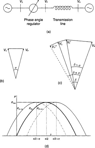
Figure 41.41(d) shows that, although the power flow for a given δ is changed by the addition or subtraction of σ, the maximum power transfer of the line is not changed. With a very fast, power electronic, tap-changer a rapid control of δ could improve the transient stability margin by providing a valuable prolongation of maximum synchronising power through the line during the first post-fault swing. Fast control could also be used to make an effective contribution to the damping of system power oscillations.
In the practical implementation of a PAR, shunt and series connected transformers are used to inject a voltage in series with the line to give the desired change of phase angle (which, for small angles, is proportional to the injected voltage). The magnitude of the injected voltage is usually made variable by means of a tap-changer. The PAR is a special case of a more general range of phase shifting transformers for which the input and output voltage magnitudes are not always constrained to be equal; the phase angle of the injected voltage depends on the chosen winding configurations of the two transformers. By incorporating power electronics, the speed of control and the flexibility of the series/shunt arrangement can be greatly increased, including unrestricted control of the phase angle in addition to the voltage magnitude.
41.8.1 Quadrature booster transformer (QBT)
One of the simplest types of phase shifting transformer is the quadrature booster transformer; Figure 41.42(a) shows the basic arrangement. One transformer is connected with its primary winding in series with the transmission line, its secondary being fed from the secondary winding of a transformer connected in shunt to the system. The magnitude and polarity of the injected voltage is usually controlled by means of an on-load tap-changer.
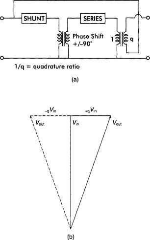
The phase angle of the injected voltage is in quadrature with the system voltage, Figure 41.42(b), and therefore the magnitude of the voltage at the output terminals of the QBT is slightly different from that at the input terminals. For a typical maximum injected voltage equal to 20% of the shunt voltage, the difference will be about 2%; the phase shift is about 11°. The NGC has installed about a dozen QBTs, with ratings up to 2750 MVA, at critical points within the transmission network on England and Wales. Phase shifting transformers are commonly used by utilities in the US to control power flow in parallel, long distance, circuits.
QBTs are usually connected in substations where they can control the power flow in one or more circuits to prevent thermal overloading. As thermal time constants of lines are measured in minutes, a conventional mechanical tap-changer can be operated quickly enough to prevent such overloads.
If there were a requirement to improve transient stability with the aid of a phase shifting transformer, the injected voltage would have to be changed much more rapidly, for example, using a thyristor-based tap-changer instead of a mechanical tap-changer.
41.8.2 Unified power flow controller (UPFC)
The UPFC, Figure 41.43(a), is a combination of a STATCOM and an SSSC and offers great flexibility of operation. In this case the secondary winding of each transformer is connected to a three phase voltage-sourced converter. The two converters are connected back-to-back as a d.c. link with their d.c. capacitors acting as a common d.c. voltage source so that, with an appropriate co-ordination between the control systems for the two converters, power can be exchanged in either direction between the shunt and series systems. In addition, each converter can be controlled to supply or absorb Mvar independently to the series and shunt systems.
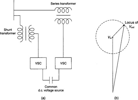
Thus, whereas a series impedance device, such as SSSC can only develop a voltage in quadrature with the current, the UPFC can generate a voltage in the series circuit with a phase angle that is controllable throughout the full range of 360°, as shown in Figure 41.43(b). When the voltage is not in quadrature with the current, power will flow out of or into the series connected converter, via the d.c. link, into or out of the power system through the STATCOM. The series converter can therefore provide impedance compensation and/or phase shifting. The STATCOM can provide voltage regulation at its point of connection independently of the power being transferred, subject only to its limits of rating.
A UPFC was commissioned in 1998 at the Inez substation of American Electric Power (AEP) in Kentucky, USA. The series and shunt units can be operated together as a UPFC or may be operated independently as STATCOM and SSSC respectively. The converters are rated at ±160 MVA and use GTOs; they are identical. A spare shunt transformer has been provided so that the converter provided for the series application is also capable of being operated as a STATCOM.
41.9 Special aspects of var compensation
The power demand of industrial loads, such as arc melting furnaces or thyristor drives for rolling mills and mine winders, varies rapidly in both magnitude and power factor. In an arc furnace the impedance of the arc can change completely from one half-cycle to the next. The changes may be particularly large during the early part of a melt; the arc can become short-circuited by scrap metal, when the furnace current is limited only by the circuit reactance, or may be interrupted completely for brief periods. This gives a current demand which fluctuates very rapidly, in an unpredictable random manner, and may take any value between zero and short-circuit current.
In thyristor drives, very large changes in energy are required during acceleration and deceleration. For instance, in a rolling mill, the drive motor is initially running at low speed and therefore at a low voltage. When an ingot enters the rolls, the drive motors are accelerated to full speed by phasing back the thyristors; this increases the current very rapidly to its rated maximum value, typically 2 to 2.5 times rated current at about 0.2–0.3 power factor lagging. The current demand falls to its full load value when the motor has accelerated to full speed. Unlike the situation in the arc furnace, the changes in power and var requirements are much more predictable, as they occur in a regular cycle and most are relatively slow.
Both kinds of load can cause voltage fluctuations due to the fast changes of var flow through the system reactance. These voltage fluctuations may be unacceptable unless the network is strengthened or reactive compensation applied. The severest limitations usually arise due to lamp flicker and sometimes due to interference with electronic control circuits of other equipment. Different types of lamp have different sensitivities to voltage change. For lamps used in a domestic environment, filament lamps are the most sensitive; their percentage brightness change is about 4 times the percentage voltage change. In comparison, for fluorescent lamps, the ratio of brightness change to voltage change is about 1. Sodium lamps are even less sensitive with a ratio of about 0.5; although high-pressure mercury vapour lamps have a ratio of about 3 they are normally found only in an industrial and not a domestic environment. Because lamp flicker caused by arc furnaces is very difficult to deal with, it will be emphasised in this section, but the general principles are applicable to the compensation of other fluctuating loads.
41.9.1 Lamp flicker compensation
The spectral density of voltage fluctuations produced by an arc furnace is approximately in inverse proportion to the square root of the frequency. People experience a subjective response to lamp flicker; generally, human sensitivity peaks just below 10 Hz for 230 V filament lamps. As can be seen from Figure 41.44, a weighted combination of these characteristics shows that the frequencies most liable to cause visual annoyance lie in a band from about 2 to 25 Hz. If the voltage fluctuations at 10 Hz are greater than about 0.2%, then they are likely to cause a noticeable flicker on the luminous output of a 230 V filament lamp. A 110 V lamp of the same wattage has a heavier filament with a greater thermal capacity, which results in a smaller response to voltage fluctuations and the most disturbing frequency is reduced to about 5 to 6 Hz.
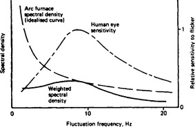
A circuit supplying an arc furnace can be simplified to that shown in Figure 41.45, where the point of common coupling (pcc) is the point in the network at which other consumers are connected. The resistance of the supply is usually small compared to the reactance, Xs, and the voltage dip at this point, Vp, is predominantly due to the variation of arc furnace var demand. If there is no SVC installed, the reactive current, Is, in the supply is the same as the furnace reactive current, Iq, and we get:
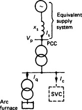
Figure 41.45 Simplified arc furnace supply circuit. PCC is point of common coupling (with other consumers)
It is thus relatively easy to estimate the magnitudes of the voltage dips caused by var fluctuations, but the annoyance caused by a sequence of rapid voltage dips is difficult to assess. In order to assess and quantify the effects of fluctuating voltage dips on the human eye and brain, a flicker meter has been developed by the International Union for Electroheat (UIE) and has been accepted by the IEC. The flickermeter measures the successive voltage fluctuations and, by means of algorithms worked out from first principles, converts them into numerical values that are compared with what 50% of the population would regard as the threshold of perceptibility for lamp flicker. For this threshold level of lamp flicker, the UIE flickermeter would give a numerical output of 1.0 for ‘short term flicker severity’ (Pst).
A flickermeter can only be applied when a furnace comes into service and cannot be used directly to predict flicker levels. However, a simple estimating procedure for planning purposes, has been derived empirically from records of complaints of flicker on many installations. This procedure evaluates the ‘short-circuit voltage depression’ (SCVD) for a proposed arc furnace; this is the change of voltage at the pcc that would be caused by a change in furnace var demand from no-load to a steady three-phase short-circuit on the electrodes. If the SCVD is greater than about 2%, consumers are likely to suffer sufficient annoyance to complain about lamp flicker. For an arc furnace installation with an SCVD of about 1.3%, the UIE flickermeter would typically indicate a maximum Pst value of about 1.
The SCVD criterion can be used to assess the maximum furnace rating that should be connected to a given system, but it can only be used to determine the rating of a compensator for flicker reduction provided that the compensator is capable of reducing all flicker frequencies in the visual annoyance range reasonably equally. Where a compensator has an acceptably linear fluctuation frequency versus speed of response characteristic up to about 25 Hz, then, if connected as shown in Figure 41.45, a steady state calculation of SCVD can be used to estimate its rating, i.e. the compensator current jIc makes up the difference between the allowable −jIs and the value of −jIq. A high speed of response is essential for flicker reduction. It has been shown that if the compensator has a control-time delay of 10 ms, no matter what its rating, it can give very little reduction of flicker; with a time delay of 20 ms or greater, a range of frequencies within the visual annoyance range will be strongly accentuated. A thyristor switched capacitor compensator, for example, cannot achieve the necessary speed of response to reduce the arc-furnace flicker in the frequency range above 5 Hz, where the human eye is most sensitive.
The harmonic-compensated saturated reactor without a slope-correction circuit has been used to give flicker reduction of up to 3:1. It has been employed successfully in many installations as a bus-bar compensator (Figure 41.46(a)), having been designed on the basis of the SCVD criterion. The tapped-reactor/saturated-reactor scheme (Figure 41.46(b)) has been used to obtain a flicker reduction of up to 7:1 for a single arc-furnace. In this scheme the saturated reactors are single-phase devices and the slope correction is achieved by the tapped reactor winding ratios; this compensator inherently compensates for the unbalance loadings of the arc furnace and gives an instantaneous response. It produces considerable harmonic distortion and requires substantial filtering.
The TCR used as a bus-bar compensator can be made suitable for arc-furnace compensation with a flicker reduction of about 2:l. Voltage-sourced converters, because of their lower reactances and capability for much faster response, can outperform conventional TCRs; present indications point to a flicker reduction of about 4:1 being obtainable.
41.9.2 Phase balancing
Three-phase a.c. systems are intended to operate in a balanced mode. Unbalance can have detrimental effects on equipment connected to the system; rotating plant is particularly sensitive due to additional losses and consequent excessive heating. Most rotating plant is able to accept only 1 % of negative phase sequence voltage continuously and 2% for short periods.
Most loads of significant size are 3-phase and operate in a balanced manner. The main exceptions are arc furnaces, mentioned above, and substations supplying a.c. traction loads. Unbalance is also caused by the physical asymmetry of transmission lines; on long lines it is usual to minimise this unbalance by regular transposition of the conductors. In rural distribution systems, unbalance is sometimes caused by unequal distribution of the many single-phase loads between the three phases.
Arc furnaces are unlikely to cause adverse unbalance effects without first causing complaints of lamp flicker. The corrective action of any flicker suppression equipment will normally also limit unbalance contributions to acceptable levels.
The unbalance caused by traction systems has sometimes been corrected by means of conventional thyristor controlled equipment with one phase providing conventional power factor correction and the other two acting as a controllable Steinmetz circuit, Figure 41.47, for balancing the power component of traction load. The asymmetrical operation of the three phases of the SVC requires the shunt capacitors to be arranged to filter low order harmonics.
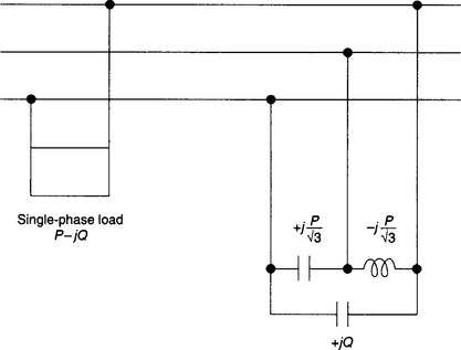
Converter technology now provides an alternative method of phase balancing with a nominally lower rating of equipment. A voltage (or current) sourced converter is used to generate an nps current which is equal in magnitude but in phase opposition to the nps current of the traction load. It thus acts as an active filter for unbalance.
41.9.3 Switched resistors
Switched resistors do not come under the strict heading of reactive power plant but have been used in certain situations to complement such plant. In situations where system transient stability is threatened by loss of synchronism due to the acceleration of a suddenly unloaded generator, switched braking resistors can provide a temporary substitute load for the generators and prevent excessive acceleration. By using thyristor switches instead of mechanical switches, fast repetitive switching can be used to aid in damping system swings.
Thyristor switched resistors have also been used with an arc furnace which comprised a significant proportion of the load on a set of gas turbine generators. In order to reduce maintenance requirements, it was desirable to operate the generators at a fairly steady load and to smooth out the rate of change of load when the furnace was suddenly switched off. This was done by thyristor switching of shunt resistors.
41.9.4 Harmonic currents and harmonic filter design
Many types of plant draw a distorted, non-sinusoidal current from the supply system, as, for instance, large rectifiers (aluminium smelters), controlled converters (traction drives, mine winders, rolling mills) and discharge lamps. The millions of low power, harmonic-producing devices used in the home and workplace, such as light dimmers, television receivers and personal computers also make a surprisingly large contribution to the total voltage distortion on many systems. Power transformers (due to magnetising currents), h.v.d.c. converter stations, SVCs and many other FACTS controllers are sources of waveform distortion in the network itself. These currents and the consequent voltage waveform distortions can be described in terms of fundamental and harmonic frequency components using Fourier analysis.
The harmonic content of voltages and currents can have undesirable disturbing effects on the system and its loads and on adjoining telecommunication circuits. Inductive or capacitive coupling between telephone and power lines induces harmonic interference over the audio-frequency range, and appropriate weighting factors are applied to the individual frequencies when assessing total distortion effect using measures such as telephone interference factor (TIF). The increased use of fibre-optic communication circuits has reduced the extent of this telephone interference.
Rotating generators and induction motors experience increased power loss due to the flow of harmonic currents. Waveform distortion can sometimes cause maloperation of electromagnetic as well as static protective relaying equipment. Shunt capacitor banks primarily for power factor correction are particularly affected by harmonics, as their impedance falls inversely with frequency so that they tend to act as ‘sinks’ for high frequency harmonic currents and may overload due to increased losses. Shunt capacitors form a resonant circuit with respect to the rest of the system at some frequency above the fundamental (i.e. at a super-synchronous frequency); if the resonant frequency is close to that of a local source (or sometimes even a remote source) of harmonic current, large and potentially damaging harmonic overvoltages and current magnifications can occur. For these reasons, harmonic distortion must be limited to acceptable levels by careful system design and, where necessary, by installation of shunt harmonic filter equipment at appropriate system bus-bars.
In order to minimise adverse harmonic effects, supply authorities apply harmonic current and voltage distortion limits, based on observed disturbances and on a desire to protect other consumers and telecommunication services. Compliance with the limitations at the point of common coupling with other loads may require reduction of system impedance by addition of lines or transformers, or the connection of the distorting load to a different point in the network. In case of converter loads the pulse number may have to be increased from 6 to 12, or even 24.
Connection of a properly designed harmonic filter consisting of a combination of inductive, capacitive and resistive elements at a suitable bus-bar will provide a low-impedance shunt path to the flow of harmonic currents generated by the distorting loads. The filter and the system will share the harmonic current injected by the load in the inverse ratio of their respective impedances. The desired impedance pattern of the filter circuit can usually be achieved by an appropriate combination of single-frequency tuned arms and broadband damped arms, Figure 41.48.
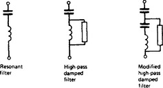
The system impedance varies with harmonic frequency in a complex manner, as most systems are not purely inductive. Systems have intrinsic resonant frequencies and, at these frequencies, there are dramatic changes in impedance from inductive to capacitive for only a few per cent variations in frequency. The supply system will, in general, have many different operating configurations and, to take account of the worst conditions, the system impedance vector is sometimes assumed to lie within a circular segment limited by maximum impedance angles. In simpler industrial circuits, the supply impedance is usually dominated by transformer impedance; this transformer impedance is assumed to increase in proportion to frequency to give the system harmonic impedance. This simplifying assumption can also be made (in the absence of other data) if the system up to the point of connection of the filters is not primarily composed of long lines or cables.
The system may contain several harmonic sources other than the particular known loads, or SVCs, or h.v.d.c. converters; in the assessment of the voltage distortion levels and filter component current ratings the effects of such ‘preexisting’ harmonics must be included.
The high-pass damped filter shown in Figure 41.48 is sometimes advantageous compared with sharply tuned arms if the filter is to be satisfactory over a wide range of system operating frequency (e.g. from 49 to 51 Hz); but such damped arms can have greater losses. The modified damped filter is of particular use if the frequencies of the harmonics to be passed are low, as the loss in the resistor can then be excessive at the fundamental frequency unless it is shunted by the series L–C circuit tuned to the fundamental frequency. Such a filter is specifically useful for suppressing unintended resonances at ‘non-characteristic’ frequencies (e.g. second harmonic) which are inherently low in current magnitude and thus would not give large loss in the resistor at these harmonic frequencies.
The optimum design of a combination of different filter arms (tuned, damped, etc.) to achieve a particular harmonic impedance pattern requires an economic assessment of the effects of choosing different relative proportions (in terms of fundamental Mvar) of the filter arms. The choice is governed not only by the harmonic performance requirements, but also by the fundamental plus harmonic ratings of the filter components—in particular, the capacitor banks. The effects of variations in the filter impedance with system frequency, temperature and component tolerances should be taken into account. The choice of the filter combination should also ensure that the non-characteristic harmonics (e.g. second, third or fourth order), which may be relatively small, are not excessively magnified by unintended resonances between the filter itself and the system. The need to minimise fundamental plus power–frequency losses in the filters also plays an important role in the final choice of the design.
41.10 Future prospects
There has been considerable progress in the field of var control during the last few years. A number of ‘future prospects’ of only 10 years ago have now been developed into practical FACTS controllers. In the field of shunt var compensation, several different types of voltage-sourced converter are being used in the various STATCOMs that are now in service in transmission systems. TCSCs are being used to provide series compensation of long transmission lines. The concept of the SSSC combined with a STATCOM to form a UPFC has been realised in a unit rated at ±160MVA and progress has been made towards the installation of an IPFC. In distribution systems there are a number of DVRs providing protection against voltage dips for sensitive loads. Several active filters have been put into service.
41.10.2 Further advances
41.10.2.1 Development of power electronic devices
Many of the developments of power electronic switching devices that have already taken place have been in response to the needs of the large market for industrial drives rather than the needs of the supply industry; this situation is likely to continue. Developments are generally directed towards the reduction of forward voltage drop and overall losses, improved ratings, increased switching speeds and smaller physical size.
41.10.2.2 Development of converter designs
It must be anticipated that converter designs for FACTS controllers will evolve to incorporate the improved devices as they become available. Switching and control using conventional thyristors is mature technology and is likely to continue to be applied in FACTS controllers for many year, with relatively minor improvements. In contrast, voltage sourced converters will continue to be developed and improved as their application becomes more widespread. A particular target for improvement is likely to involve the reduction of harmonic generation by the converters and/or active filtering of harmonic distortion. In order to accommodate some types of energy storage systems, there may be increased activity in developing current-sourced converters.
41.10.2.3 Development of energy sources and storage systems
With sufficient capacity, energy storage systems could contribute to spinning reserves, peak lopping requirements and system frequency control. Battery energy storage systems (BESS) lend themselves to providing energy input to the voltage sourced converters of STATCOMs and superconducting magnetic energy storage (SMEs) is under development but improvements in the economics of energy storage are still needed. Fuel cells offer an alternative type of energy source and regenerative fuel cell systems are currently being developed.
41.10.2.4 Thyristor tap-changers
The technique of using thyristors instead of mechanical switches is available for controlling transformer tap ratios and hence for fast control of voltage and vars. The magnitude as well as the phase angle of the voltage can be made rapidly controllable, but the considerably higher cost has so far not justified their use. New types of power electronic device might improve the viability of thyristor tap-changers.
41.10.3 Future applications of FACTS controllers
41.10.3.1 Long distance transmission
Series capacitor compensation is an economic way of increasing the power transfer capacity of a line, but some of the potential gain in additional capacity may be lost when linear shunt reactors are permanently connected. Subsynchronous resonance conditions must be evaluated at the design stage, but techniques are now available for damping out SSR.
Shunt compensation using SVCs provides good voltage control along the line and at its terminals and can also result in increased transmission capacity. Further benefits arise from the combination of shunt and series compensation, which is likely to be more widely used as transmission companies seek to maximise the utilisation of their assets.
41.10.3.2 HVDC applications
It is increasingly difficult for utilities to obtain permission for the construction of new circuits, or even the up-grading of existing a.c. transmission lines. Undergrounding is extremely expensive. In such situations, the only practical way to increase the power transfer along a particular corridor may be to convert circuits from a.c. to d.c. operation. The easy controllability of d.c. can also enhance the flexibility of the rest of the a.c. system and can contribute to the damping of a.c. system phase angle oscillations. H.v.d.c. can also be used to couple adjacent, non-synchronised systems to provide mutual benefits from shared reserve generating capacity.
These applications of d.c. technology should become increasingly common.
41.10.3.3 Power quality
Power quality is judged on a range of criteria including interruptions to the continuity of supply and disturbances to the voltage magnitude, waveshape and frequency. Customers are increasingly concerned about these aspects and demanding improvements (and reduced tariffs). FACTS controllers will increasingly be used to assist in improving power quality.
41.10.3.4 Energy management systems
Modern energy management systems (EMS) provide an operator with up-to-date information on the state of his system and enable him to obtain very rapid answers to his ‘What if?’ questions. These systems can provide valuable information for longer-term system planning purposes, especially in respect of the requirements for voltage control and var management. They can also be used to supply control data for the FACTS controllers already operating within the system so that system operation can be made more robust and reliable under both normal and emergency conditions.