
Power Quality
43.1 Introduction
Power quality is an issue that is becoming increasingly important to electricity consumers at all levels of usage. Sensitive equipment and non-linear loads are commonplace in both the industrial and the domestic environment, because of this a heightened awareness of power quality is developing. Occurrences on the supply network that were once considered ‘normal’ by electricity companies and users are now considered a problem to the users of more sensitive equipment.
43.2 Definition of power quality terms
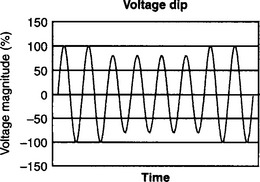
By definition a voltage dip is a reduction in the rms voltage in the range of 0.1 to 0.9 p.u. (retained) for duration greater than half a mains cycle and less than 1 minute.
Often referred to as a ‘sag’. Caused by faults, increased load demand and transitional events such as large motor starting (Figure 43.1).
43.2.2 Voltage swell
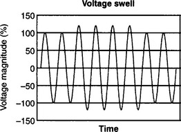
By definition an increase in the rms voltage in the range of 1.1 to 1.8 p.u. for a duration greater than half a mains cycle and less than 1 minute. Caused by system faults, load switching and capacitor switching.
The magnitude of a voltage swell is dependent upon the fault location, relative to the point of measurement, the system impedance and system earthing. An earthed system with delta–star connected substation transformer will ensure little change in the un-faulted phases voltages due to a low impedance path from fault to transformer (Figure 43.2).
43.2.3 Short interruptions
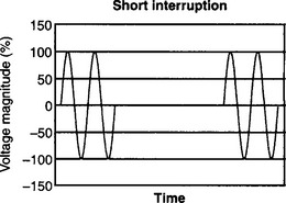
An interruption is defined as a reduction in the supply voltage, or load current, to a level less than 0.1 p.u. for a time of not more than 1 minute. Interruptions can be caused by system faults, system equipment failures or control and protection malfunctions.
Because the magnitude of the supply voltage drops below 0.1 p.u. during an interruption, the magnitude of the interruption is considered to be zero, the interruption is defined only by duration. The length of short interruptions is generally governed by the type of protection equipment utilised on the system such as auto-reclosers (Figure 43.3).
43.2.4 Transients
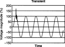
A transient is an undesirable momentary deviation of the supply voltage or load current. Transients are generally classified into two categories, impulsive and oscillatory. An impulsive transient is an abrupt change in the steady state voltage and/or current, that occurs outside the power frequency range and is unidirectional in polarity.
Impulsive transients are characterised by the rate of change of voltage or current magnitude, i.e. the rise and fall times. Oscillatory transients are generally characterised by their frequency content and duration. They are often due to the network response to an impulsive transient (Figure 43.4).
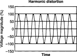
43.2.5 Harmonics
Harmonics are periodic sinusoidal distortions of the supply voltage or load current caused by non-linear loads. Harmonics are measured in integer multiples of the fundamental supply frequency. Using Fourier series analysis the individual frequency components of the distorted waveform can be described in terms of the harmonic order, magnitude and phase of each component. The quantity total harmonic distortion (THD) is commonly used, it represents a summation of all the harmonic components present in a waveform (n ≠ 1) (Figure 43.5).
43.2.6 Inter-harmonics
Distorted voltage or current waveforms containing periodic distortions of a sinusoidal nature that are not integer multiples of the fundamental supply frequency are termed inter-harmonics.
43.2.7 Flicker
A term used to describe the visual effect of small voltage variations on electrical lighting equipment (particularly tungsten-filament lamps). The frequency range of disturbances affecting lighting appliances, which are detectable by the human eye, is in the range of 1 to 30 Hz.
Flicker severity is the intensity of flicker annoyance defined by the UIE-IEC flicker measuring method and evaluated by the following quantities:
43.2.8 Voltage imbalance
Voltage imbalance is defined as a deviation in the magnitude and/or phase of one or more of the phases, of a three-phase supply, with respect to the magnitude of the other phases and the normal phase angle (120°). Voltage imbalance is more commonly a problem in rural areas where one, or two, phase(s) of a three-phase supply is/are being loaded more than the other(s). Can be expressed as a percentage of the ratio of either zero or negative phase sequence components to the positive phase sequence.
43.3 Sources of problems
43.3.1 Power electronic devices
Power electronic devices both cause and are susceptible to power quality disturbances. The most common ‘economically damaging’ power quality problem encountered involves the use of variable speed drives (see below). All computers contain a power electronic switched mode power supply (SMPS, see below) which is a cheap and convenient method of converting mains supply into low voltage d.c. without expensive transformer windings. These supplies are the cause of a significant increase in the level of 3rd, 5th and 7th harmonic voltage distortion.
43.3.1.1 Variable speed drives
Variable speed motor drives or inverters are highly susceptible to voltage dip disturbances and cause particular problems in industrial processes where loss of mechanical synchronism is an issue. The ideal solution to problems of this nature would be for planning engineers to install equipment that has a ‘reasonable level’ of susceptibility to voltage dips from the outset, this does not happen for two reasons:
43.3.1.2 SMPS (including IT equipment)
A large range of equipment, mainly office and domestic, use switch mode power supplies to convert mains to the required d.c. level. Many of these converters draw a nonlinear current from the supply which is high in third and fifth harmonic content.
Because the third harmonic is a ‘triplen’ harmonic it is of zero order phase sequence and therefore adds in the neutral of a balanced three-phase system. The increasing use of IT equipment has led to concern of the increased overloading of neutral conductors and also overheating of transformers.
Recent developments have seen the use of switch mode power supplies in fluorescent lighting applications, these lighting applications typically represent in the region of 50% of a modern building’s load. Many commercial modern buildings have large neutral conductors to cope with the levels of third harmonic, which can theoretically reach three times the magnitude of the fundamental.
43.3.2 Arcing devices
Electric arc furnaces, arc welders and electric discharge lamps are all forms of electric arcing device. These devices are highly non-linear loads the current waveform of which is characterised by an increasing arc current limited only by the network impedance. Large arc furnace installations have typical current requirements of 10s of thousands of amps, welding sets draw current in the range of 100s of amps, individual electric discharge lamps draw only fractions of an amp but when it is considered that a large percentage of the domestic and commercial load requirement is contributed by lighting requirements this has a significant impact.
All arcing devices are sources of harmonic distortion, the arcing load can be represented as a relatively stable source of voltage harmonics. The effects of arc furnaces are difficult to mitigate, balancing the phases with other furnaces will not always be effective as arc furnaces are operated in various modes leading to phase imbalance. Arc welders commonly cause transients in the local network due to the intermittent switching, some electronic equipment should be protected from the effects of these impulsive spikes. Because of the requirement to limit the current within fluorescent lights a ballast is fitted which can add to the level of harmonic distortion of the supply, of particular concern is the level of the third (or higher order triplen) harmonic. Balancing the phases to have equal harmonic load is a good way to minimise the level of the triplen harmonics, but on a star–star connected transformer connection no cancellation will occur.
43.3.3 Load switching
The effect of heavy load switching upon the local network is a fairly common problem causing transients to propagate through to other ‘electrically close’ equipment. These transients can be of surprisingly large voltage magnitude, but have very little energy due to their short duration which is normally measured in terms of milliseconds. Electronic devices which may be sensitive to these voltage impulses can have their operation impaired.
The effect of load switching on the voltage is typically encountered in the form of transient activity (as seen in Figure 43.4). This type of transient might occur as the result of switching in a heavy single-phase load, the effect seen on the voltage measured nearby. Other equipment can be protected from these switching transients by electrically isolating them from the affecting equipment.
43.3.4 Large motor starting
Because of the dynamic nature of an induction machine it draws a current depending upon the mode of operation, during starting this current can be as high as six times the normal rated current. This increased loading on the local network has the effect of causing a voltage dip, the magnitude of which is dependent upon the system impedance. It can take several seconds for motors to reach their rated speed, for this reason measures are taken to reduce the level of current drawn during motor starting. These measures are dependent upon the type of motor and drive, most modern motors employ a sophisticated power electronic converter ‘drive’ which in most cases will control the motor’s starting current to a reasonable level. Some lower cost types of motors use series capacitors or resistors to reduce the starting current, these components are then switched out once the motor’s rated speed has been reached. Autotransformers are used to start some older motors, these have a variable secondary winding which allows the motor stator voltage to be controlled and hence the current drawn from the supply.
43.3.5 Embedded generation
Increasing levels of embedded generation predicted in the future are likely to have an effect on power quality. Although it can not be stated that this increased level of dispersed generation on public distribution networks will degrade or improve power quality (this is an issue of some contention) it can be said that there are both advantages and disadvantages to the more widespread application of embedded generation where power quality is concerned.
An increased amount of embedded generation at substation level and below will lead to increased fault levels in the feeders. This increased fault level is one of the major concerns when considering embedded generation issues leading to calls for increased protection.
The voltage of embedded generators, when located at some distance from a substation, must be controlled to ensure power flow from the high voltage (substation bus) to the lower voltage (embedded generator connection).
With wind turbines voltage fluctuation due to variations in wind speed leads to problems with voltage regulation and therefore potential power quality problems on a local level. When a wind turbine blade, rotating at relatively low speed, passes the supporting pylon, the blade is momentarily inefficient in converting the airflow into rotational velocity, this leads to a low frequency ‘pulsing’ causing a continuous flicker problem at the generator output. This effect can be quite extreme in areas electrically close to a windfarm connection.
43.3.6 Sensitive equipment
If it were not for sensitive equipment, power quality would not have become such an issue in recent years as it has. Equipment manufactures are designing and manufacturing ever more sophisticated equipment as time goes on much of which is increasingly susceptible to variations in power quality. There are many issues relating to the subject of equipment sensitivity, the main areas of concern are:
• Reduced equipment operating life.
• Instantaneous equipment malfunction.
• Equipment malfunction to data corruption.
As mentioned previously variable speed drives are a major problem. These drives are power electronic converters and are prone to voltage dips of relatively small magnitude.
Any device which depends upon a volatile memory chip for information storage is potentially at risk from power quality events, IT equipment therefore requires protection. Computer central processing units are prone to damage from power quality and quality of supply disturbances, the repeated thermal shock of being energised and de-energised can lead to permanent damage and early failure. Many processes in industry depend upon automated microprocessor control systems. Solutions to the power quality problems encountered with this type of equipment often consists of protection for the control system alone, the actual process not being sensitive to the more common disturbances.
A large part of the problem with sensitive loads is down to inadequate legislation. The EMC limits EN 61000-3 series cover many electromagnetic compatibility requirements that manufacturers of equipment must meet.
The area of susceptibility to voltage dips is not covered in enough depth, manufacturers are being allowed to sell equipment that is too sensitive to voltage dips. There are reasons why these ‘loop-holes’ in the EMC directive exist, one is that the regulations are based on statistical occurrences, another is that the regulations have to account for existing equipment.
43.3.7 Storm and environment related damage
Lightning strikes are a cause of transient overvoltages often leading to faults. Lightning does not have to strike a conductor in order to inject transients on to the local network, ‘impulses’ can be induced if lightning strikes near a conductor. The local ground potential can be raised by a nearby strike leading to neutral current flowing to earth via a remote ground, this can have destructive effects on sensitive equipment. Lightning strikes which hit overhead lines often cause ‘flashovers’ to neighbouring conductors as the insulators break-down, the strike will therefore not only consist of a transient overvoltage but also fault clearing interruptions and dips.
High winds and storm conditions cause widespread disruption to the supply networks. Where disruptions are caused by faults that can be cleared in less than one minute, by the use of auto-reclosers for example, the effect on the network is seen as a power quality issue. Long interruptions, above one minute, are generally seen as reliability or quality of supply issues.
Snow and ice build-up have a severe effect on the reliability of overhead lines, this has obvious power quality/quality of supply consequences.
Sea mists in the vicinity of overhead lines can lead to flashover between conductors, insulators must be cleaned on a regular basis in these areas to avoid these problems. In hot and humid climates dust and heavy dew can cause similar flashover problems requiring non-intrusive insulator cleaning methods.
Damage due to wildlife and trees is common in rural areas, particularly in the spring. As with any faults these are potential causes of power quality problems.
43.3.8 Network equipment and design
Auto-reclosing circuit-breakers are commonly used on rural radial networks to allow faults time to clear and supply to continue without the requirement for manual intervention. The circuit-breakers have the purpose of increasing the security of supply, fuse saving and reducing outage time. As far as customers are concerned they can however cause power quality problems due to the way in which they operate. Fast tripping is the use of circuit-breakers or line reclosers to trip in a very short period of time under fault conditions, this is another method of saving fuses, but has an adverse effect on power quality. As most faults on rural networks are of a transient nature, when such a fault occurs the auto-recloser will trip, after a predetermined time delay the circuit-breaker will reclose. If the fault has cleared then the supply is fully restored and no more disruption will occur, if the fault was not cleared then the breaker will trip again (for up to 4 times). It is this repeated reclosing that is a power quality issue, customers will have their supplies reconnected for each of the instants when the auto-recloser re-connects the supply, this can lead to equipment damage in extreme circumstances. To reduce the level of customer annoyance caused by the repeated operation of auto-reclosers these devices are normally set with a built in ‘dead-time’ which allows the fault more time to clear prior to recloser operation. A ‘lock-out time’ can also be set which will stop the unit from reclosing if a certain number of operations have taken place within a pre-set time window.
Capacitor switching is a major cause of transients on the supply network. Capacitors are used to provide reactive power compensation (vars) hence reduce system losses. Some capacitors are permanently connected to the network, others are switched to suit the load conditions. When capacitors are switched in to a supply, voltage transients occur due to the interaction of the network inductive elements and the additional capacitance. Where power factor correction capacitors are installed at a customer’s site and utility capacitor switching is taking place the effect of the switching transient can become magnified and oscillatory in nature. This ‘voltage magnification’ is a function of the impedance of both the capacitance’s, the network, end user circuit inductance and the capacitor switching ‘frequency’. If the resonance frequency of the end-user circuit and the network resonance in response to the capacitor switching are equivalent, then the maximum voltage magnification will occur. This can amount to double the nominal supply voltage in extreme cases.
Tap-changing transformers are used for the purpose of voltage regulation. They can have either mechanical or electronic devices for changing the transformer tapping to vary the secondary voltage level. Electronic tap changers can respond to load changes in a very short time frame, mechanical devices are more suited to more predictable slower changing loads.
Current limiting fuses are used where the fault current is high and have the effect of improving the overall power quality by isolating such a fault in a very short time frame. Typically rated in thousands of Amps the fuses will isolate a faulted connection in less than half a mains cycle.
Transformer energisation causes large oscillatory inrush currents that have an adverse effect on power quality each time a transformer is switched in to the network. The energisation of a transformer can cause dynamic overvoltages for up to one second after it is switched in, the inrush current is highly distorted. Particular problems are encountered when transformers are connected to power factor correction capacitors, the problem can be eliminated by switching the devices in separately. Ferro-resonance can occur in distribution networks, at frequencies below 300 Hz, as the result of transformer inrush current harmonic components and series connected capacitors resonating with the transformer magnetising inductance. To combat this effect capacitors are de-tuned from known resonance frequencies.
Network sectionalising on a radial distribution network consists of the use of line reclosers in strategic positions which will allow increased probability of continued supply to more critical loads under fault conditions.
Surge arresters are used in areas where lightning strikes are a frequent occurrence. They have non-linear characteristics which allow current surges, induced by lightning to be ‘bled-off’ to earth. Surge, or lightning, arresters are typically fitted on every few poles on LV systems in lightning prone areas.
Line shielding is another method of reducing the effect of lightning on overhead lines in storm-prone areas. More commonly used on transmission lines, the ground conductor is supported above the phase lines thus reducing the possibility of faults caused by lightning strikes. Line shielding adds substantial cost to a distribution line because the poles must be higher and the benefits of having neutral conductors beneath the phase lines are removed.
43.4 Effects of power quality problems
Power quality can have a large detrimental effect on industrial processes and the commercial sector. Industrial processes differ in their requirements, from a power quality perspective, each having particular ‘weaknesses’ in terms of power quality attributes. The important power quality considerations to be accounted for to the industrial end-user centre around costs associated with machine down-time, clean-up costs, product quality and equipment failure. Solutions to power quality problems must be implemented by industrial end-users which reflect the cost versus benefit case for implementation.
Domestic customers tend not to be so adversely affected by power quality problems in that equipment in the home tends to depend less upon a high degree of power quality in its normal operation. However, trends in home ownership of IT equipment and sophisticated communications equipment for home entertainment purposes will mean a shift in power quality requirements for worst affected customers in the near future.
Table 43.1 shows power quality quantities and their most common effects on end-users.
Table 43.1
Power quality, quantities and effects
| Quantity | Effect |
| Voltage dips | Machine/process downtime, clean up costs, product quality and repair costs all contribute to make these type of problems costly to the end-user. |
| Transients | Component failure, hardware reboot required, software problems, product quality. |
| Harmonics | Transformer and neutral conductor heating leading to reduced lifespan. Audio Hum, Video ‘flutter’, software glitches, power supply failure. |
| Flicker | Visual irritation. |
43.5 Measuring power quality
The first consideration after having identified a PQ problem is the economic case for solving the problem, it is therefore important to try and quantify the cost of the problem to the end user. It would be useful if the customer could provide information of:
• The nature of the power quality problem
• The estimated cost of the disturbance
• The times at which the problem occurred
• Information about the equipment affected
In order to quantify the less obvious or hidden costs associated with a PQ problem it is necessary to implement a scheme of monitoring at the site of the problem.
A thorough site survey should be carried out prior to adopting a scheme of monitoring, this should consist of:
• Review of site circuit diagrams.
• Obtain detailed information of loads affected.
• Obtain detailed information of suspect loads.
• Equipment failure/malfunction logs.
• Identify the ‘significant’ problem areas.
After all the above information has been collected and considered, if no obvious cause is apparent, then a scheme of monitoring should be adopted to suit the power quality problem. A detailed scheme of monitoring will require some important decisions to be made from the outset, if the outcome of the monitoring is to be of maximum benefit:
• The type of monitoring equipment to be used.
• Where to connect the monitoring equipment.
Measurable quantities in power quality include; supply voltage variations, short/long interruptions, voltage dips and swells, harmonics, inter-harmonics, flicker, voltage imbalance, frequency deviation.
43.6 Amelioration of power quality problems
A large number of reported power quality problems are caused by incorrect earthing practices. Verification of earthing arrangements, particularly when harmonics problems are reported, should always be conducted early in a power quality investigation.
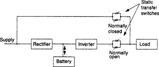
43.6.2 Standby UPS
Consisting of a rectifier, battery, inverter and static-switches, the standby UPS is the most popularly used UPS available today. The static transfer switches will be controlled to allow the load to be fed from the mains supply under normal operation, when there is a mains disturbance leading to a reduction in the mains voltage below some predetermined level the switches will open and close respectively. The load will then be fed from the battery, via the inverter ensuring continuation of supply to the load. The inverter output of a standby UPS must always operate in synchronism with the supply frequency to ensure a smooth transition from one supply to the other (Figure 43.6).
43.6.3 On-line UPS
An on-line UPS is configured such that the load is always fed from the UPS, in this way the load is isolated from the mains supply at all times. These systems are in general expensive and have high operating losses. Very similar to a standby system to view schematically, but with a manual transfer switch in place of the static transfer switches.
43.6.4 Hybrid UPS
The hybrid UPS system has a configuration similar to standby UPS systems, with the exception that some form of voltage regulator, such as a ferro-resonant transformer, is used in place of the static switch device(s). The transformer provides regulation to the load and momentary ride-through when the transfer from mains supply to standby UPS is made.
43.6.5 Local or embedded generation
A form of local generation, such as a diesel generator, can be connected to allow for any shortfall in the mains capacity and also to provide ride-through for power quality disturbances. This will in most circumstances be viewed as an expensive solution, as the cost to keep a diesel generator running on-line indefinitely would be a high price to pay for improved power quality. However, some forms of embedded generation, such as micro-turbines, fuel cells and Stirling engines, are likely to have increased domestic usage in the near future.
43.6.6 Transfer switches
Transfer switches are used to transfer a load connection from one supply to another, allowing the choice of two supplies for the load (or sub network), should one supply suffer power disturbances then the other supply will be automatically switched in reducing the possibility of supply disruption to the load.
43.6.7 Static breakers
The power electronic equivalent of a circuit-breaker with a sub cyclic-response time. The static breaker will allow the isolation of faulted circuits in the shortest possible time frame, other nearby loads will therefore have improved power quality.
43.6.8 Active filters and SVCs
The control of reactive power, and therefore harmonics, can be achieved by controlling a proportion of the power systems current through a reactive element. Conventionally this is achieved by switching inductors and capacitors in shunt with the power system, using thyristors. With the SVC the control of the current is achieved by controlling the output voltage magnitude of an inverter. SVCs are used to absorb or inject reactive currents to eliminate the harmonic distorting currents drawn by non-linear loads.
Unified power flow controllers (UPFCs) are similar to SVCs but allow both series and shunt compensation.
43.6.9 Passive filters
Passive filters or power line filters are simple filters consisting of discrete capacitors and/or inductors. Normally designed to attenuate high frequencies (low pass filters), fitted to equipment to remove higher order harmonic frequencies from the supply.
43.6.10 Energy storage system
All electrical energy storage systems have the same basic components, interface with power system, power conditioning system, charge/discharge control and the energy storage medium itself. Each storage medium has different characteristics, energy density, charge/discharge time, effect of repeated cycling on performance and life, cost, maintenance requirements etc. These characteristics help to make the decision of what storage medium is best suited to which application, each medium having merits that make it the most suitable in different circumstances. Energy storage systems available:
43.6.11 Ferro-resonant transformers
A constant voltage, or ferro-resonant, transformer is normally a transformer with a 1:1 turns ratio and with a core that is highly magnetised close to saturation under normal operation. The variation of primary voltage has a much-reduced effect on the secondary voltage, hence the output is not significantly effected by voltage sags.
43.7 Power quality codes and standards
Below is a list of the most commonly used standards and recommendations used in the field of power quality within the European community and USA.
(i) EN 50 160 (2000) ‘Voltage characteristics of electricity supplied by public distribution systems’.
(ii) EN 61000-2-2 (1993) EMC Environment section. ‘Compatibility levels for low-frequency conducted disturbances and signalling in public LV power supply systems’.
(iii) EN 61000-3-2 (1999) EMC Limits. ‘Limits for harmonic current emissions (Equipment input current less than or equal to 16 A per phase)’.
(iv) EN 61000-3-3 (1998) EMC Limits. ‘Limitation of voltage fluctuations and flicker in low voltage supply systems for equipment with rated current less than or equal to 16 A’.
(v) EN 61000-3-4 (1998) EMC Limits. ‘Limits for harmonic current emissions (Equipment input current greater than 16 A per phase)’.
(vi) EN 61000-3-5 (1994) EMC Limits. ‘Limitation of voltage fluctuations and flicker in low voltage supply systems for equipment with rated current greater than 16 A’.
(vii) EN 61000-3-6 (1996) EMC Limits. ‘Assessment of emission limits for distorting loads in MV and HV power systems’.
(viii) EN 61000-4-7 (1995) ‘EMC testing and measurement techniques—General guide on harmonics and interharmonics measurements and instrumentation, for power supply systems and equipment connected thereto’.
(ix) EN 61000-4-11 (1994) ‘EMC testing and measurement techniques—Voltage dips, short interruptions and voltage variation immunity tests’.
(x) Engineering recommendation G.5/4 (2001) ‘Planning levels for voltage harmonic distortion and the connection of nonlinear equipment to transmission systems and distribution networks in the UK.’
(xi) Engineering recommendation P28 (1989) ‘Planning limits for voltage fluctuations caused by industrial, commercial and domestic equipment in the United Kingdom’.
(xii) Engineering recommendation P29 (1990) ‘Planning limits for voltage unbalance in the United Kingdom for 132 kV and below’.
(xiii) ITIC (Information Technology Industry Council) Curve—the ITI (CBEMA) curve, published by the technical committee 3 (TC3), of the information technology industry council Supersedes CBEMA (Computer and Business Equipment Manufacturers Association) curve.
(xiv) IEEE Std 1159 (1995) ‘Recommended practice for monitoring electric power quality’.
(xv) IEEE 446 (1995) ‘Recommended practice for emergency and standby power systems for industrial and commercial applications—IEEE orange book’.
(xvi) IEEE 519 (1992) ‘Recommended practice and requirements for harmonic control in electrical power systems’.
(xvii) IEEE 1100 (1993) ‘Recommended practice for powering and grounding electronic equipment—IEEE Emerald Book’.
(xviii) IEEE 1159 (1995) ‘Recommended practice for monitoring electric power quality’.
(xix) IEEE 1250 (1995) ‘Guide for service to equipment sensitive to momentary voltage disturbances’
(xx) IEEE 1346 (1998) ‘Recommended practice for evaluating electric power system compatibility with electronic process equipment’.