
Chapter 8
Biofuels, Bio-Power, and Bio-Products from Sustainable Biomass: Coupling Energy Crops and Organic Waste with Clean Energy Technologies
Serpil Guran, Foster A. Agblevor and Margaret Brennan-Tonetta
8.1 Introduction
Coupling sustainable biomass with emerging clean energy technologies can provide transformational opportunities for low-carbon energy and bio-based products manufacturing in developing low-carbon economy. Changing supply and demand dynamics in the energy sector and especially recent developments of increased supply of transition fuels, demand for energy resources worldwide, the potential negative impacts of climate change, and the need to develop a sustainable and resilient national low-carbon energy supply will require alternatives to existing fossil fuel resources. Recent horizontal drilling achievements in national gas supplies when compared with coal and oil may seem to reduce the CO2 emissions; however, the assessments show that natural gas domination would still heat up the planet [1]. To accelerate switch from fossil transition fuels to low-carbon energy sources, solutions are critically needed to contribute to sustainability goals and provide for today's energy demands while conserving limited resources for future generations. The development and deployment of new and innovative clean energy systems may offer solutions that are environmentally sustainable, economically viable, and socially equitable. To achieve this result, it is critical to understand, test, scale up, and prove existing and emerging clean energy technologies and verify “sustainable clean energy pathways.”
8.2 Sustainable Biomass for Sustainable Development
The term sustainable development is an important concept, and its definition was first introduced in the Brundtland Report in 1987 [2]. In 2015, United Nations released 17 sustainable development goals as part of the 2030 Agenda forSustainable Development [3]. These 17 goals include various target areas spanning from ending poverty and achieving nutritional food supply for all by sustainable agriculture to ensuring reliable and affordable access to clean water and energy. The agenda is a plan of action for people, planet, and prosperity. These 17 goals were set to help to understand the interdependent nature of these pillars, act on effectively, and help guide decision-making, innovation, and deployment of technologies that bring us closer to sustainably developed clean energy systems.
There is a critical need to find alternatives to meet the increasing demand for energy, to accelerate economic growth by market transformation, and to mitigate climate change. Aggressive energy planning at the international, national, state, and local government levels is needed that are based on reasonably achievable targets [4]. Solutions will require complex strategies for both energy demand and supply that simultaneously and rigorously reduce emissions and eliminate other environmental concerns such as ecodiversity and healthy habitats while promoting a low-carbon economy. Demand strategies include aggressive programs at all levels for energy conservation and efficiency from home heating and lighting to manufacturing and transportation. On the supply side, increases in the use of renewable power and fuel will be critical and will include sustainable biomass (e.g., purpose-grown wood and other energy crops, agricultural waste, and biomass waste) options, among other renewables. Promoting sustainable clean energy pathways can provide possible solutions to the growing energy problem and achieve overall sustainable development goals.
8.2.1 Food–Energy–Water (FEW) Nexus Concept:
The United Nations projects that the world population will reach 8.5 billion by 2030 and 9.7 billion by 2050. The challenge to provide food, energy, and water (FEW) to current and future populations is immense because food, energy and water are tightly linked and interdependent:
- There is energy embedded in every gallon of water.
- There is water embedded in every kilowatt hour of energy used and every mile traveled.
- There is water and energy embedded in every calorie of food and fiber produced.
As a result, making decisions and taking action in one area creates direct and indirect impacts in other areas. Therefore, the FEW Nexus concept and its components and relationships need to be well understood to avoid creating additional problems while trying to avoid unintended consequences while trying to solve FEW-related problems [5–7].
8.2.1.1 Sustainable Biomass
Sustainable biomass has been long discussed and is a well-debated matter. For instance, the use of first-generation biofuels, such as corn ethanol and soy bean biodiesel, have raised numerous environmental concerns such as greenhouse gas (GHG) emissions, land use change, loss of carbon sinks, and increased carbon release from soils [8–10]. In addition to social concerns over the food-to-fuel pathway and diverting food crops to energy generation, there are additional concerns about land use problems associated with traditional energy crops that should be avoided. These land use problems include clearing additional land for agriculture, increasing the net carbon footprint by releasing stored soil carbon, and eliminating the carbon sink function of the once-intact ecosystem [9, 10]. Considering the development of new types of sustainable energy crops and the potential for utilizing unrecycled fractions of waste along with coupling them with efficient clean energy technologies can help alleviate many of these issues.
Often, “biomass” and “sustainable biomass” are used interchangeably with the intention of promoting sustainable biomass-to-energy and bio-products pathways. Some biomass definitions only include agriculture-based biomass such as dedicated fuel crops, crop residues, short rotation woody crops, and native vegetation [10]. However, it is important to expand this definition to include all viable sustainable biomass feedstocks that can support the low-carbon bioenergy and bio-products industries.
Thus, the authors recommend the following definition for sustainable biomass.
Sustainable Biomass
Biomass feedstocks do not follow food-to-fuel pathways and do not result in forest conversion and/or land clearing for biomass production plantations. Organic matter including agricultural crop residues (i.e., straw, husks, corn cobs, leaves, brunches), dedicated and non-invasive fuel crops (fast-growing trees and grasses, i.e., aspen, poplar, willow, switch grass), native vegetation, forest residues, animal manure (i.e., equine, dairy, and poultry), aquatic species (i.e., algae, duckweed), and unrecycled biomass in waste streams (food waste, yard waste, unrecycled waste paper, cardboards, untreated waste wood, landfill gas, biogas from digester including wastewater treatment facilities) used as feedstocks and inputs in bioenergy and bio-products industries for low-carbon energy (low-carbon power and heat, advanced biofuels, drop-in fuels, renewable compressed natural gas (CNG) and liquefied natural gas (LNG) applications), and bio-based products manufacturing to displace fossil-based counterparts.
8.2.1.2 Determining Biomass Sustainability
The efforts to develop certification standards that can be used to determine biomass sustainability are ongoing and still evolving [11–14]. Overall, the criteria for certification of sustainable biomass to energy and end products include the following basic components:
- Environmental sustainability
- Economic sustainability
- Social equity
- Legality
- Transparency
8.2.1.2.1 Environmental Sustainability and Food–Energy–Water Nexus
When considering bioenergy alternatives, it is critical to evaluate the environmental impact of all relevant energy options and pathways and assess the outcomes. First, the production of biomass used for bioenergy (power, heat, and transportation fuels) and bio-products manufacturing should meet existing air, water, and soil quality standards. Second, a “field-to-wheels” or “cradle-to-grave” GHG-based life cycle analysis (LCA) should be conducted to assess whether the carbon footprint of the proposed bioenergy resource and/or bio-product is lower than the carbon footprint associated with the fossil-based energy or products that will be displaced. In addition to carbon footprint assessment, comprehensive environmental footprint analysis including water footprint analysis of bioenergy systems should be performed. Sustainable biomass production should follow sustainable agriculture practices that include consideration of biodiversity, native species, wildlife and their habitats, natural resource protection, potential for invasive crop spread, soil erosion, and land conversion. Considering all of these factors will provide the basis for making a well-informed decision on bioenergy/bio-product options that meet low-carbon and reduced environmental impact goals because making decisions and taking action in one area creates direct and indirect impacts in other areas. Therefore, the FEW Nexus concept and its components and relationships need to be well understood to avoid creating additional problems while trying to avoid unintended consequences while trying to solve FEW-related problems [8, 9].
8.2.1.2.2 Social Equity
Social benefits from sustainable biomass-to-bioenergy and bio-products pathways should include affordable and easy access to energy, increased job opportunities that pay fair wages, increased income, and better living standards.
8.2.1.2.3 Economic Sustainability
Sustainable biomass-to-bioenergy and/or bio-products pathways should be economically feasible and stimulate economic development. A detailed cost-benefit analysis of bioenergy and bio-products pathways should prove that in fact sustainable biomass can serve as an economically viable alternative for industry and society.
8.2.1.2.4 Legality
Compliance with all the local, federal, and international environmental, agricultural, and industrial laws and requirements is essential while promoting biomass-to-energy and bio-products pathways. Legal considerations should also serve to prevent child labor, promote better working standards for all, and protect intellectual property rights.
8.2.1.2.5 Transparency
Transparency of findings from research and assessments is essential in the promotion of sustainable biomass-to-bioenergy and bio-products industries, particularly regarding the results of field-to-wheels LCA of bioenergy and bio-products alternatives, so that well-informed decisions can be made.
8.3 Biorefineries and Bioenergy Conversion Pathways
8.3.1 Biorefineries
In petroleum refineries, crude oil is distilled into gasoline, diesel, naphtha, kerosene, lubricating oils, and asphalts. The naphtha fraction is also used as production of benzene, toluene, and xylene (BTX) and other platform chemicals, that is, butadiene, ethylene, and propylene, which are used as intermediaries for production of many end products. Although naphtha and biomass are similar, biomass has high oxygen content and includes many different types of non-fossil organic matter. Therefore, conversion of biomass feedstocks into bioenergy and bio-based products involves a broad diversity of existing and emerging pretreatment and conversion technologies. A biorefinery is defined as a facility that can produce multiple products from multiple feedstocks by integrating multiple conversion technologies and manufacturing systems. They can take advantage of the differences in biomass components and intermediaries and maximize the value derived from the biomass feedstocks [15]. Based on the available feedstocks, a biorefinery can be designed to produce a mixed portfolio of products, such as one or several low-volume, but high-value, chemical products and low-value, but high-volume, liquid transportation fuels. The high-value products can create profitability, while the high-volume fuel production can help achieve national transportation fuel production goals. Additionally, a biorefinery can generate power and heat for its own use, potentially export excess power to the grid, and/or provide heat to nearby industries for revenue. This diversified approach can reduce costs, increase profitability, and help mitigate climate change by reducing GHG emissions overall. However, pursuing this pathway requires research and development in critical technology areas, technology scale-up and pilot plants, demonstrations, best management practices, outreach and education, and preparation of the workforce for tomorrow's technologies.
Life Cycle Analysis of Bioenergy and Bio-products
To assess the net impact of bio-power, biofuels, and bio-based products as compared with petroleum or other biomass derived counterparts, a complete understanding of the environmental footprint of the feedstocks, processes, and end products is critical. However, this is not an easy task and has many challenges such as [12]
- Data integrity issues
- Correct carbon accounting
- Diversity of conversion technologies
- Direct and indirect land use effects
- Time frames used
- Market uncertainty
Direct land use change and indirect land use change (iLUC) effects, such as indirect emissions, should be included in the “field-to-wheels” or “cradle-to-grave” LCA. The issue of indirect emissions from land use change refers to the concept that increasing demand for globally traded feedstocks (e.g., corn, soy, wood) for biofuels and bio-based products has the potential to change world markets such that new lands are cleared or substantially altered to accommodate the additional demand. Initial studies have shown that changes in global land use to meet demand for bio-based feedstocks have the potential to result in high levels of GHG emissions that, on a lifecycle basis, eliminate or even outweigh the GHG benefits of displacing fossil fuels with biofuels [12–14].
8.3.2 Biomass-to-Bioenergy and Bio-products Conversion Pathways
Biomass conversion into power, heat, fuels, and bio-products varies based on the specific feedstock and is generally categorized into two major conversion pathways – biochemical and thermochemical (Figure 8.1).
8.3.2.1 Biochemical Conversion Processes
Biochemical processes include anaerobic digestion (AD) of organic waste (food waste, agricultural waste, some high moisture animal manure, yard clippings, and sludge) to generate biogas and by-products that can be utilized for soil remediation and production of liquid fuels from lignocellulosic feedstocks through acid and/or enzymatic hydrolysis. Also, production of first-generation biofuels through fermentation can be classified as a biochemical conversion technology. In this chapter, the transesterification process is included in the chemical/biochemical conversion category, though some researchers prefer to categorize it as a physiochemical conversion technology. Additionally, this chapter is intended to provide information on non-food biomass and organic waste-to-bioenergy and bio-products pathways such as direct fermentation of cornstarch and other starches that can be utilized as food sources and transesterification of soy bean oil and other straight vegetable oils that can serve as food sources, including palm oil into biodiesel production, are not discussed. However, waste starch to alcohols and waste oils to biodiesel pathways are included.
8.3.2.1.1 Anaerobic Digestion Pathway
AD occurs in an oxygen-depleted environment through a series of chemical reactions by specific species of microorganisms. The microorganisms digest the organic feedstocks and break them down in stages and produce biogas [17]. Suitable feedstocks for AD include organic waste, namely, food waste from institutional, commercial, industrial, and residential sources wastewater/sewage sludge and farm animal waste, particularly dairy farm waste. Controlled AD requires an airtight vessel that can serve as a digester. An anaerobic digester has to maintain a minimum temperature of 20 °C to promote bacterial activity. Higher temperatures of up to 60 °C are more beneficial as it shortens processing time, thus allowing the digester to handle a larger volume of organic feedstocks [17]. Based on the type of bacteria and its optimal digestion temperature, the ADs can be classified as thermophilic and mesophilic. A mesophilic bacterium is a microorganism that performs best between 35 and 45 °C and “thermophilic” bacterium is a microorganism that performs best between 50°C and 60 °C [17, 18]. The biogas (also known as digester gas) is actually a mixture of gases, with methane and carbon dioxide making up more than 90% of the total volume. In addition, biogas typically contains small amounts of hydrogen sulfide (H2S) (see Figure 8.2).
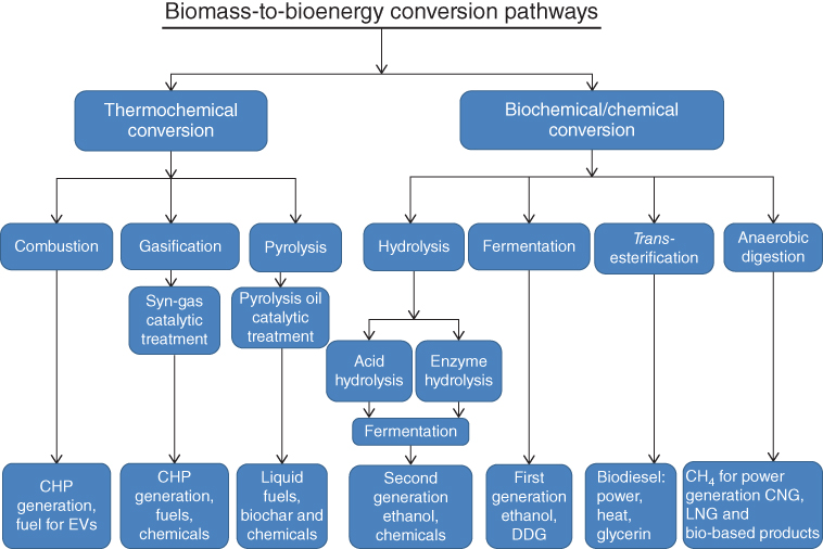
Figure 8.1 Biomass conversion pathways [16].

Figure 8.2 Organic waste anaerobic digestion to energy concept.
The first option is to site the facility near a transfer station that accepts unsorted waste. Following mechanical separation of metals, plastics, and glass, the remaining organic fraction of the waste can be pulped and fed directly into the AD system for biogas generation. Second, ADs can be colocated within existing landfills to utilize the waste-management infrastructure already in place. This approach can help existing landfills increase gas generation and collection efficiencies and also serves as an important component of an efficient waste management operation. Third, if colocation with landfills and transfer stations is not feasible, AD applications can be developed as stand-alone facilities. Finally, ADs colocated with wastewater treatment facilities can utilize source separated organic waste generated by the facility, since the AD technology is already in use.
It is important to recognize that every link of the biogas economic value chain needs to be profitable and environmentally sustainable, as well as socially acceptable. For example, to prevent unpleasant odors from affecting surrounding areas, AD systems may be required to implement certain safeguards such as installation of bio-filters and granular activated carbon (GAC) filters and/or maintain negative pressure in the AD chambers during operation. Similarly, to reduce noise and associated emissions pollution due to trucking organic waste to the AD system, the facility should be constructed in close proximity to the sources of the organic waste streams.
8.3.2.1.1.1 Biochemical Reactions in Anaerobic Digestion
The conversion of organic waste to biogas is accomplished through four stages of biochemical reactions, which are known as hydrolysis, acidogenesis, acetogenesis, and methanogenesis [19, 20].
- 1.
Hydrolysis: The first stage of AD breaks down the organic waste feedstock into its components. In this stage the following conversion reactions occur:
- Lipids → fatty acids
- Polysaccharides → monosaccharides
- Protein → amino acids
These reactions are catalyzed by enzymes excreted by bacteria such as cellulase, protease, and lipase [21]. If the biomass polymer is complex, the hydrolysis phase occurs slowly. Therefore, high lignin-containing biomass, such as woody waste, is not a feasible feedstock for AD conversion. Carbohydrates, however, can be converted easily to simple sugars [19]. The chemical formula of an organic waste mixture can be presented as C6H10O4, and the hydrolysis stage can convert the mixed organic waste into simple sugars [21, 22]:

- 2. Acidogenesis: During this stage, acid-forming reactions occur, and products of hydrolysis are converted into primarily short chain acids such as lactic, formic, propionic, butyric, or succinic acids. In addition, ketones and alcohols are formed.
- 3. Acetogenesis: This stage converts long fatty acids formed from the hydrolysis of lipids to acetate through carbohydrate fermentation. CO2 and H2 are also produced at this stage. The role of hydrogen as an intermediary is of critical importance to AD reactions in this stage.
- 4. Methanogenesis: During this stage, methane is produced. This reaction is very sensitive to pH changes. Optimum pH levels are neutral to slightly alkaline, and if the pH level becomes too acidic, essential microorganisms cannot survive and carry out the desired reactions [21, 22].
8.3.2.1.1.2 Anaerobic Digestion Reactors
AD reactors can be classified by the total solids (TS) content of the slurry in the digester. Low solids (LS) reactors contain less than 10% TS, medium solids (MS) reactors contain about 15–20% TS, and high solids (HS) processes range from 22% to 40% TS. The disadvantage of LS reactors is the large quantity of water in the slurry that requires large reactor volumes and expensive posttreatment dewatering technology at the end of the process. HS reactors are more robust and have high organic loading capacity. In addition to being categorized by the solids content, AD rectors can be further classified as
- 1. Single stage: Single-stage low solids (SSLS) or single-stage high solids (SSHS)
- 2. Multistage: Multistage low solids (MSLS) or multistage high solids (MSHS)
- 3. Batch: Single-stage batch, sequential batch, and hybrid batch
Single-stage AD processes utilize a single reactor for both acidogenic and methanogenic stages. Depending on the solids content, they can either be SSLS or SSHS. HS applications in single-stage reactors are more efficient but more expensive due to the need for conveyor belts and powerful pumps. However, the pretreatment is less problematic than LS applications. Single-stage reactors both in LS and HS applications do not require mechanical devices for stirring and mixing.
Multistage AD processes occur in two stages with hydrolysis, acidogenesis, and acetogenesis occurring in the first stage and methanogenesis occurring in the second stage. The two stage process results in an increased rate of hydrolysis in the first stage and longer retention time in the second stage, which allows for optimum growth rate of microorganisms and maximized methanogenesis. These reactors can also be classified as MSLS or MSHS. The LS and HS application differences are similar to the single-stage applications.
Batch type reactors are operated by loading the reactor vessel with the materials in a slurry form to be decomposed, allowing the AD reactions take place and emptying the remaining biomass fully or partly after the completion of the reactions. The remaining biomass in the reactor following the AD reactions can be used to activate the subsequent batch operation. Batch reactors can be single-stage batch, sequential batch, or hybrid batch. Batch process offers the advantages of being technically simple, inexpensive, and robust [20–24].
Landfill Gas and Digester Gas as Renewable Natural Gas (RNG)
AD of organic waste can occur in digesters and landfills to produce anaerobic digester gas (biogas) and landfill gas, respectively. Both gases are a mixture of methane (CH4), carbon dioxide (CO2), and other impurities based on the feedstock. These gases are also called renewable natural gas (RNG) [25] if they contain 50–65% methane. The organic waste AD to biogas generation concept can be applied to clean power generation, or it can be utilized as CNG in transportation. Additionally, the solid and liquid residue following AD can be utilized as compost. Utilization of landfill gas for power and heat generation can help displace fossil fuels and reduce the adverse effects of fossil fuel utilization, such as air emissions that include criteria pollutants and GHG emissions. However, widespread utilization of landfill gas and digester gas from sewage sludge/wastewater treatment to power generation pathways is being challenged by the presence of volatile methyl siloxanes (siloxanes), which damage power generation equipment. Siloxanes are found in wastewater and the solid wastes deposited in landfills. They are formed as a result of the hydrolysis of polydimethylsiloxanes (PDMS). PDMS are a class of organosilicon compounds used in the manufacturing of industrial products and household products, such as personal hygiene and healthcare products [26]. When landfill gas or other forms of RNG are combusted in gas turbines, boilers, microturbines, or internal combustion engines to generate power, siloxanes convert into silicon dioxide (SiO2) and deposit in the various parts of the power generation equipment. This results in high maintenance costs, prolonged downtime and even serious equipment failure. Deposition on turbine blades, heat exchangers, and emission control equipment can result in reduced or total loss of heat transfer efficiency, equipment failure, and possible poisoning in catalytic converters, requiring expensive repairs and service interruptions [27]. The level of siloxanes varies depending on the feedstock source. Concentrations can be as high as 140 mg/m3, which is significantly above the 15 mg/m3 limit recommended by most equipment manufacturers [28]. Current siloxane removal technologies can be categorized as wet or dry removal technologies. These technologies include adsorption onto activated carbon or silica gel, chilling, refrigeration, and condensation or liquid scrubbing by absorption into solvents [29]. These technologies have been reported to be moderately effective [29]. Biological removal of siloxanes not only is reported to be possible but also poses significant challenges [30]. In addition to these technical difficulties, other important factors in siloxane removal are environmental impacts and cost of the technology.
8.3.2.1.2 Transesterification Pathway
The transesterification reaction converts oils and fats (triglycerides) into biodiesel and glyceride by-products. A triglyceride, by definition, contains a glycerine molecule with three long-chain fatty acids attached (Figure 8.3). When converting triglycerides into esters, alcohol reacts with the fatty acids to form mono-alkyl esters, namely, biodiesel and glycerol. Methanol and ethanol are widely used alcohols in this process. The resulting biodiesel products can be defined as fatty acid methyl ester (FAME) and fatty acid ethyl ester (FAEE), respectively [31–34]. The conversion reaction takes place utilizing catalysts such as sodium hydroxide or potassium hydroxide.
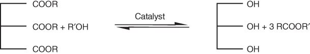
Figure 8.3 Transesterification reaction of triglycerides for biodiesel production. (Ferreira et al. [31], https://www.hindawi.com/journals/isrn/2012/142857/. Used under CC BY 3.0, https://creativecommons.org/licenses/by/3.0/.)
8.3.2.1.2.1 Transesterification of Waste Oils and Lipids from Non-food Sources into Biodiesel
Biodiesel is a synthetic diesel-like fuel produced from vegetable oils by the transesterification process described above and is an alternative to petroleum–diesel. In addition to plant oils (soybean oil, canola oil, cottonseed oil, palm oil), biodiesel can be produced from recycled cooking greases or oils (e.g., yellow grease, brown grease), animal fats (beef tallow, pork lard), or lipids extracted from high-lipid-forming aquatic species (i.e., algae and duckweed species) [31, 34–37].
Biodiesel blends easily and completely with fossil diesel fuel at any concentration. Currently, most diesel engines are able to run-on blends up to B20 (20% biodiesel and 80% fossil diesel fuel by volume) with few or no engine modifications [32, 33, 36, 37].
8.3.2.1.2.2 Waste–Oils (Yellow Grease and Brown Grease) to Biodiesel
Yellow grease is defined as waste vegetable oil or animal fats collected after cooking. Yellow grease cannot be used directly as a replacement for fossil diesel fuel unless the engine is specifically designed to combust it [35, 36]. Converting yellow grease into biodiesel results in better engine performance. Yellow grease may contain several types of fats, including animal fats, and contains high concentrations of free fatty acids (FFA) (up to 10%) [24] that pose significant processing problems in alkali-catalyzed processes. Prior to the transesterification process, yellow grease and animal fats need to be treated by an acid-esterification step to remove the FFA. Removal is accomplished by the addition of extra alkaline catalysts or homogeneous acid catalysts, causing esterification of the FFA. Another treatment approach is converting FFA in yellow grease into monoglycerides and then proceeding with transesterification.
8.3.2.1.2.3 Brown Grease
Brown grease can be defined as grease from restaurant grease traps and sewage grease and can serve as a viable feedstock to produce biodiesel [33]. It generally has higher FFA than yellow grease (∼ >20%) and can also be used for animal feed. Brown grease is gelatinous at ambient temperatures and has high odor levels. Pumped trap grease is typically disposed of at wastewater treatment plants or landfills. Trap grease can contain contaminants such as pesticides, fungicides, and herbicides, polycyclic hydrocarbons, detergents cleaners, trace metals, aflatoxins (from molds), and/or perchloroethylene from dry cleaning operations [32, 36]. Biodiesel production from brown grease involves more steps than yellow grease and, prior to transesterification, requires physical refining as follows [36]:
- 1. Degumming: Brown grease consists of a high amount of phosphatides that cause gumming. Degumming treatment involves hydration with water or orthophosphoric acid.
- 2. Bleaching: This step removes residues of phosphoric acid generated by the degumming process.
- 3. Caustic refining, steam stripping, solvent extraction, and adsorption can be applied as needed to improve the physical properties of brown grease to make it more easily utilized in biodiesel production [36–38].
8.3.2.1.2.4 Non-food Lipids to Biodiesel
Lipids from aquatic species including algal species are receiving considerable interest as a feedstock for biodiesel production. Conversion of aquatic species into biofuels will be discussed in Section 8.3.2.1.4.
8.3.2.1.3 Hydrolysis of Biomass and Organic Wastes into Cellulosic Ethanol
Due to controversial concerns created by ethanol production from corn feedstocks, such as food-to-fuel pathways and iLUC emissions, there has been great interest in finding new conversion pathways for non-food biomass feedstocks. Therefore, biomass-to-sugars pathways are emerging to utilize cellulose and hemicellulose contents of biomass as possible fuel production options. Wood waste, agricultural waste, forestry residue, non-recycled organic waste, and purpose-grown energy crops such as switch grass and poplar are viable feedstocks for this pathway (Table 8.1) [39].
Table 8.1 Cellulose, hemicellulose, and lignin contents in common agricultural residues and wastes
| Lignocellulosic material | Cellulose (%) | Hemicellulose (%) | Lignin (%) |
| Hardwood stems | 40–55 | 24–40 | 18–25 |
| Softwood stems | 45–50 | 25–35 | 25–35 |
| Nut shells | 25–30 | 25–30 | 30–40 |
| Corn cobs | 45 | 35 | 15 |
| Grasses | 25–40 | 35–50 | 10–30 |
| Paper | 85–99 | 0 | 0–15 |
| Wheat straw | 30 | 50 | 15 |
| Sorted refuse | 60 | 20 | 20 |
| Leaves | 15–20 | 80–85 | 0 |
| Cotton seed | 80–95 | 5–20 | 0 |
| Newspaper | 40–55 | 25–40 | 18–30 |
| Waste papers | 60–70 | 10–20 | 5–10 |
| Primary wastewater solids | 8–15 | — | — |
| Solid cattle manure | 1.6–4.7 | 1.4–3.3 | 2.7–5.7 |
| Coastal bermuda grass | 25 | 35.7 | 6.4 |
| Switch grass | 45 | 31.4 | 12 |
| Swine waste | 6.0 | 28 | 0 |
Source: Prasad et al. 2007 [39]. Reproduced with permission of Elsevier.
8.3.2.1.3.1 Acid Hydrolysis
Acid hydrolysis is usually performed by adding mineral acids such as sulfuric acid (H2SO4) or hydrochloric acid (HCl). The concentrated acid ruptures the cellulose chain by breaking the hydrogen bonding. Once the cellulose is de-crystallized, it forms a homogenous gelatine and becomes extremely susceptible to hydrolysis [40–42]. Water is used to dilute this mixture at modest temperatures (40–60 °C) to extract xylose (C5 sugars) and glucose (C6 sugars). The sugars then undergo a standard fermentation process to produce ethanol. In addition to ethanol, acid hydrolysis processes can be designed to produce butanol and levulinic acid for other fuel and chemical needs. Acid hydrolysis applications require reactors that are resistant to corrosion, since the concentrated acid is highly corrosive [40]. Acid hydrolysis is also used in a dilute form to pretreat biomass to prepare for enzymatic hydrolysis.
8.3.2.1.3.2 Enzymatic Hydrolysis
Enzymatic hydrolysis is performed by using cellulase enzymes to convert cellulosic feedstocks (especially those high in lignin) into monomeric sugars that are subsequently fermented into ethanol using the following processes:
- 1. Pretreatment: The first step in enzymatic hydrolysis is pretreatment of biomass to free the cellulose fraction by disrupting the lignin. The goal of the pretreatment process is to break down the lignin structure and disrupt the crystalline structure of cellulose so that the acids or enzymes can easily access and hydrolyze the cellulose [43, 44]. Pretreatment methods can be categorized as physical (milling and grinding), physicochemical (steam pretreatment/autohydrolysis, hydrothermolysis, and wet oxidation), chemical (alkali, dilute acid, oxidizing agents, and organic solvents), biological, electrical, or a combination of these methods [44].
- 2. Enzyme application step: The most common enzyme types are cellulase enzymes which are used to hydrolyze cellulose into glucose. Also, hemicellulases and other enzymes can be used to release sugars from different parts of biomass as follows:
- Cellulases are used to hydrolyze cellulose to glucose.
- Xylanases are used to hydrolyze xylan into xylose. Removal of xylan from lignocelluloses increases the accessibility of cellulose for enzymatic hydrolysis.
- Peroxidases and laccases are two effective groups of enzymes that are used for degradation of the lignin component of biomass, which increases accessibility to cellulose enzymes. These agents serve as efficient lignocellulose-degrading enzymes, which are necessary in order to reduce the cost of enzymes required in the biomass-to-ethanol process [43–47].
8.3.2.1.4 Advanced Biofuels Production from Aquatic Biomass
In addition to development of advanced fuels from cellulosic feedstocks and the organic fraction of municipal solid waste, a number of other viable feedstocks are emerging for biofuels production. Aquatic species-to-biofuels can be categorized as third-generation advanced biofuels. Currently, aquatic species-to-biofuel pathways are not commercialized, and they are in their infancy in terms of research, development, and deployment. However, early research shows that these feedstocks hold potential for advanced biofuels production. There are many benefits (described below) associated with algae and other aquatic plants, such as duckweed species, that would make “aquatic plants to biofuels” a viable pathway for manufacturing transportation fuels and bio-based products. In addition, these plants are suitable for CO2 fixation and wastewater treatment [48].
8.3.2.1.4.1 Algae to Biofuels
The term algae can refer to microalgae, cyanobacteria (blue-green algae), and macroalgae (seaweed) [49]. Algae are single-cell aquatic organisms that photosynthesize [50–53]. Algal production can offer high biomass yields per acre, and it has been demonstrated that algae cultivation can minimize or avoid competition with arable land and nutrients used for conventional agriculture practices [49]. Some algal strains are capable of doubling their mass several times per day. In some cases, more than half of that mass consists of lipids or triacylglycerides [54]. Algae cultivation does not always require freshwater and can utilize wastewater or saline water. In addition, algae can recycle carbon from CO2-rich emissions from stationary sources including power plants and other industrial emitters [49, 54, 55]. Depending on the type, algae can be utilized for both ethanol and biodiesel production.
Starch-Forming Algae for Ethanol Production
Cyanobacteria and macroalgae primarily produce carbohydrates, which can be a viable source for advanced ethanol production. Some types of cyanobacteria grow very quickly, and the quantity of biomass can double in less than 10 h. Despite recent advancements, a comprehensive understanding of the carbon metabolism of cyanobacteria is still not sufficient to guide researchers in the selection of suitable species for fuel production. Macroalgae and seaweed are also high in carbohydrates, which can be converted into various fuel types including ethanol [49]. A major obstacle of bioethanol production from microalgae is degrading the hard cell walls that surround the starch particles. Degrading and removing the cell wall improves access and enzyme conversion [54].
Lipid-Forming Algae for Biodiesel Production
Many algae are rich in lipids, which can serve as an excellent feedstock for biodiesel production. Strains have been identified that produce greater than 80% of their dry weight as lipids [55, 56]. Most algae species are capable of converting CO2 and water to O2 and biomass through photosynthesis. This type of cultivation is usually called “photoautotrophic cultivation” and can be achieved in open ponds, in raceways, in closed photobioreactors, or on special growth membranes. Photobioreactors use much less water than open ponds but have strict temperature requirements, which can result in high cooling costs.
Biodiesel from algae is receiving renewed attention because it does not follow a food-to-fuel pathway as first-generation feedstocks, such as soybean oil or rapeseed oil. Microalgae typically will produce more oil, consume less space, and can be grown on land unsuitable for traditional agriculture. However, environmental implications such as excessive water usage and fertilizer inputs still need to be optimized. Microalgae to fuels pathways need to also include the reutilization of the algal waste in environmentally sustainable and economically feasible ways [48, 49, 56–58].
8.3.2.1.4.2 Duckweed to Biofuels
The Lemnaceae (duckweed) is a small floating aquatic plant that usually blooms through vegetative budding [59]. Duckweed is a monocotyledon with 37 species distributed among five genera (Landoltia, Lemna, Spirodela, Wolffia, and Wolfiella). Duckweed can grow in wastewater with high nutrient concentrations in an environmentally friendly manner. Because of its tolerance of high nutrient levels and excellent nutrient uptake, it has been studied as a tertiary treatment of municipal and industrial wastewater, as well as for nutrient recovery from swine wastewater [60]. Based on the species and growing conditions, duckweed starch content may reach up to 75% (dry weight basis) [59, 61]. The high starch content of duckweed makes the plant a potential feedstock for bioethanol production [60, 61]. A compositional analysis indicates that duckweed cell wall material is rich in cellulose and pectin and contains little lignin. This also makes duckweed enzymatic conversion attractive because it may need significantly reduced pretreatment and enzyme applications [61–63].
8.3.2.2 Thermochemical Conversion Processes of Biomass
Thermochemical technologies that can be used to convert sustainable biomass (purpose-grown energy crops, wood chips, algae, duckweed) and organic waste (agricultural waste, forestry waste, farm waste) into energy forms (heat, power, and fuels) can be categorized as combustion, gasification, and pyrolysis. Thermochemical conversion has several advantages, including the possibility of converting all the major components of biomass, namely, cellulose, hemicellulose, and lignin. Thermochemical conversion is typically utilized with solid, low moisture biomass. The diverse nature of biomass feedstocks, agricultural wastes, dedicated energy crops, forestry wastes, and agro-industrial wastes can reduce efficiency if the most suitable conversion technology is not selected.
8.3.2.2.1 Direct Combustion
Direct combustion is the most common methodology to convert solid biomass feedstocks into heat and power or combined heat and power (CHP) [64]. Direct combustion is a chemical reaction between the biomass fuel and pure oxygen or air that produces carbon dioxide and water along with heat release. Direct combustion systems oxidize biomass to generate hot flue gas that can be used for heat or fed into a boiler to generate steam. The steam can then be used in a steam turbine to generate electricity [65, 66]. Various forms of biomass fuels such as wood logs, chips, pellets, saw dust, forest residues, and straw are commonly used in small combustion appliances such as wood stoves, pellet burners, pellet boilers, wood log boilers, and wood chip boilers [64]. Industrial use of biomass for energy is primarily solid biomass especially industrial, forestry, and agricultural residues in the form of pellets. Traditionally, pellet mills are typically located near sawmills and utilize the saw dust waste to form pellets. However, large pellet mills also use wood residues and in some cases wood logs as raw material, but the feedstock is mainly local [64, 67]. Biomass fuel properties are the defining parameters for the technology to combust them. The most important fuel properties for combustion are the proximate analysis and heating value of biomass. Proximate analysis provides fixed carbon (char), volatile, moisture, and ash content assessment of biomass, while ultimate analysis examines elemental percentages of C, H, O, N, S, and Cl in a given biomass sample (Table 8.2).
Table 8.2 Ultimate and proximate analyses of various lignocellulosic biomass [75]
| Biomass type | Ultimate analysis (db, % w/w) | Proximate analysis (% w/w) | LHV (MJ/kg) | |||||||
| C | H | O | N | S | Ash | VM | FC | M | ||
| Cedar wood | 51.10 | 5.90 | 42.50 | 0.12 | 0.02 | 0.3 | 80–82 | 18–20 | —a | 19.26 |
| Wood sawdust | 46.2 | 5.1 | 35.4 | 1.5 | 0.06 | 1.3 | 70.4 | 17.9 | 10.4 | 18.81 |
| Olive oil residue | 50.7 | 5.89 | 36.97 | 1.36 | 0.3 | 4.6 | 76 | 19.4 | 9.5 | 21.2 |
| Rice husk | 45.8 | 6.0 | 47.9 | 0.3 | — | 0.8 | 73.8 | 13.1 | 12.3 | 13.36 |
| Rice straw | 38.61 | 4.28 | 37.16 | 1.08 | 0.65 | 12.64 | 65.23 | 16.55 | 5.58 | 14.40 |
| Pine sawdust | 50.54 | 7.08 | 41.11 | 0.15 | 0.57 | 0.55 | 82.29 | 17.16 | —a | 20.54 |
| Spruce wood pellet | 49.3 | 5.9 | 44.4 | 0.1 | — | 0.3 | 74.2 | 17.1 | 8.4 | 18.5 |
| Coffee husk | 46.8 | 4.9 | 47.1 | 0.6 | 0.6 | 1.0 | 74.3 | 14.3 | 10.4 | 16.54 |
| Coffee ground | 52.97 | 6.51 | 36.62 | 2.8 | 0.05 | 1.0 | 71.8 | 16.7 | 10.5 | 22 |
| Larch wood | 44.18 | 6.38 | 49.32 | 0.12 | — | 0.12 | 76.86 | 14.86 | 8.16 | 19.45 |
| Grapevine pruning waste | 46.97 | 5.8 | 44.49 | 0.67 | 0.01 | 2.06 | 78.16 | 19.78 | —a | 17.91 |
| Jute stick | 49.79 | 6.02 | 41.37 | 0.19 | 0.05 | 0.62 | 76–78 | 21.4–23.4 | —a | 19.66 |
| Sugar-cane bagasse | 48.58 | 5.97 | 38.94 | 0.2 | 0.05 | 1.26 | 67–70 | 28.74–30.74 | —a | 19.05 |
| Com cob | 40.22 | 4.11 | 42.56 | 0.39 | 0.04 | 2.97 | 71.21 | 16.11 | 9.71 | 16.65 |
| Peach stone | 51.95 | 5.76 | 40.7 | 0.79 | 0.01 | 0.65 | 81.3 | 18.1 | 8.53 | 21.6 |
| Wheat straw | 46.1 | 5.6 | 41.7 | 0.5 | 0.08 | 6.1 | 75.8 | 18.1 | —a | 17.2 |
| Cotton stem | 42.8 | 5.3 | 38.5 | 1.0 | 0.2 | 4.3 | 72.3 | 15.5 | 7.9 | 15.2 |
| Straw | 36.57 | 4.91 | 40.70 | 0.57 | 0.14 | 8.61 | 64.98 | 17.91 | 8.5 | 14.6 |
| Camphor wood | 43.43 | 4.84 | 38.53 | 0.32 | 0.1 | 0.49 | 72.47 | 14.75 | 12.29 | 17.48 |
| Beech wood | 48.27 | 6.36 | 45.2 | 0.14 | — | 0.8 | 81 | 18 | —a | 19.2 |
| Switch grass | 47 | 5.3 | 41.4 | 0.5 | 0.1 | 4.6 | 58.4 | 17.1 | 20 | 18.7 |
Source: Adapted Alauddin et al., 2010 [75].
a – Dry Basis
VM, volatile matter; FC, fixed carbon; M, moisture.
8.3.2.2.1.1 Biomass Combustion Basics
Although combustion of biomass is considered an oxidation process, it consists of a complex series of thermal decomposition reactions including drying, devolatilization, gasification, char formation, combustion, and gas phase reactions. When biomass is heated its components start to hydrolyze, oxidize, dehydrate, and pyrolyze with increasing temperatures, forming combustible volatiles, tarry substances, and char. The decomposition products of cellulose, hemicellulose, and lignin first undergo partial and complete oxidation reactions. Composition and physiochemical properties of biomass are the determining parameters for duration and rate of the steps of the oxidation process [67, 68].
Particle formation and uncontrolled emissions from biomass combustion are raising growing health concerns about using direct combustion as a technology option. Research shows that combustion of biomass is a common source of particulate matter (PM) and gaseous emissions such as polycyclic aromatic hydrocarbons (PAH), volatile organic compounds (VOC), carbon monoxide, nitrogen oxide, and sulfur oxide [66, 70, 71]. Based on the biomass fuel type and combustion conditions, particle formation can be categorized as soot particles, organic particles, and ash particles. In any size application, emissions should be controlled for pollutants and meet air quality regulations. Particle control technologies include
- Cyclones
- Multicyclones
- Core separators
- Cartridge filters
- Electrostatic precipitator (ESP)
- Fabric filters (baghouses)
- Rotating particle separators
8.3.2.2.1.2 Types of Direct Combustion Boilers
Direct combustion to electricity applications can utilize two types of systems, namely, fixed-bed and fluidized-bed combustion.
- Fixed-bed combustion systems burn biomass on a grate or underfeed stokers and release the hot flue gases into a heat exchanger system to generate steam. When primary air passes through the fixed bed, biomass drying, partial gasification, and initial charcoal combustion take place. The combustible gases then are burned in a separate zone. Underfeed stokers feed biomass into the combustion chamber by screw conveyors from below and transfer biomass upward on a grate.
- Fluidized-bed combustion utilizes an incombustible suspended bed (usually sand) where the biomass is burned to release flue gas. Fluidized-bed boilers can be categorized based on the fluidization type, namely, bubbling or circulating fluidized beds. In bubbling fluidized-bed applications, the bed particles are suspended by the primary air at comparatively lower fluidization velocities (∼1–3 m/s), whereas in circulating bubbling fluidized-bed designs, higher gas velocities (∼3–6 m/s) are applied and solids leave the combustion zone. Additional bed materials are reintroduced by circulating the material again [67, 68]. The fluidized-bed application increases heat transfer to achieve improved efficiency and close to complete oxidation reactions with reduced emissions. However, this method has greater standby power needs than fixed-bed boilers [64].
8.3.2.2.1.3 Co-firing Biomass
Co-firing biomass with fossil fuels is receiving increased attention as a way to reduce the adverse effects of coal burning for energy, including GHG mitigation. Research reviews report over 100 successful co-firing demonstrations in 16 countries that use biomass species including herbaceous woody and waste biomass in various types boilers (tangential, wall, and cyclone fired) [68, 72, 73]. Co-firing biomass with coal can generate a substantial reduction in NOx, SOx, and GHG emissions from direct coal combustion. Generally, up to 15% biomass can efficiently be co-fired with coal without drastic reduction in efficiency or retrofitting [74].
8.3.2.2.2 Gasification (Syngas Platform)
Gasification is a thermochemical conversion process in which carbonaceous substances such as biomass are partially oxidized and converted into gaseous products [69, 75, 76]. The product gas, commonly referred to as producer gas or syngas, consists mainly of hydrogen (H2), carbon monoxide (CO), carbon dioxide (CO2), water (H2O), and small amounts of hydrocarbons such as methane (CH4) [72, 75, 76]. Depending on the feedstocks used, the syngas can also contain alkali, metal compounds, sulfur, nitrogen, carbonyl sulfide, ammonia, and cyanide (HCN). Following gasification, syngas needs to be cleaned prior to further utilization. Syngas is best used as a fuel for stationary power and heat generation or to manufacture a range of fuels, chemical intermediates, and end products [69].
Gasification is one of the promising technologies that are being widely researched to convert sustainable biomass and waste biomass into energy forms, as it adds value to low or negative-value feedstocks into marketable fuels and products [69].
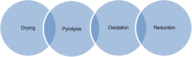
Figure 8.4 Biomass gasification stages.
8.3.2.2.2.1 Biomass Gasification Basics
The chemistry of biomass gasification consists of four consecutive reactions that take place in a partial oxidation process. These reactions usually overlap without any definitive limits (Figure 8.4) [69, 75–77]. Providing a valid theory to describe the entire biomass gasification process is very complex due to the variety of biomass feedstocks that can be used and their specific characteristics, reaction thermodynamics, pressure, and temperature conditions [78]. In addition to air, pure oxygen, and steam can be used as a gasifying agent. It has been shown that gasification with air results in a gaseous product with low to medium heating value (4–7 MJ/Nm), whereas gasification with oxygen or steam results in a medium heating value (10–14 MJ/Nm) [75]. Although steam gasification leads to higher amounts of H2 yields, it requires higher operating temperatures to vaporize water and is proven to be an expensive approach. Research indicates that a mixture of air/steam at variable ratios would contribute to more efficient syngas production [79, 80]. In summary, the following operating parameters define efficient gasification of biomass: the type of gasifying agent, gasifying agent/biomass ratio, biomass moisture content, residence time, reaction temperature, pressure, air–fuel ratio, and catalyst additives.
Biomass gasification stages: As previously mentioned, the gasification process for biomass takes place in four stages: drying, pyrolysis, oxidation, and reduction (see Figure 8.4). A description of each stage is as follows:
- Drying: The moisture content of biomass is highly variable and can range from 30% to 60%. During the drying stage, the moisture level of the biomass feedstock should be reduced to 10–15%.
- Pyrolysis: In this stage, the breakdown of biopolymers occurs at 150–400 °C along with the formation of char and condensable and noncondensable gases. This stage is influenced by type and particle size of biomass, heating rate and maximum temperature, residence time, and pressure.
- Oxidation: During oxidation, the char, formed in the pyrolysis stage, is oxidized to CO2 and water. This stage releases a large amount of heat as a result of the oxidation of carbon and hydrogen.
- Reduction: The sub-stoichiometric amount of oxygen will initiate partial oxidation of carbon releasing carbon monoxide. In addition, several reduction reactions occur as follows:
- C + H2O → CO + H2
- C + CO2 → 2CO
- CO2 + H2 → CO + H2O
- C + 2H2 → CH.
8.3.2.2.2.2 Gasifier Types
A gasifier is a chamber in which the biomass and gasifying agent are mixed at certain ratios and at certain temperatures and in some applications with inert materials such as catalysts. Design and operation of gasifiers require an understanding of the effects of various biomass characteristics and operating conditions on the performance of the system. Gasifier designs have been researched for more than a century and are classified by [77, 81]
- Gasifying agent: Air-blown, steam, and oxygen
- Heating type: Direct or auto-thermal, indirect
- Reactor pressure: Atmospheric or pressurized
- Reactor design: Fixed bed, fluidized bed, and entrained flow
The most common classification of gasifiers is based on the design of the reactors [69, 75–78].
- 1. Fixed-bed gasifiers are also known as moving bed reactors. Depending on the air flow in the chamber, they can be further grouped as updraft fixed-bed, downdraft fixed-bed, cross-draft fixed-bed, and open-core fixed-bed gasifiers. These work by piling the biomass on top of a grate inside the gasification chamber, and the fuel bed moves slowly down the reactor as the gasification reactions proceed. These types of gasifiers are simple, inexpensive, and proven to be easy to operate. However, they produce gas with low energy content.
- 2. Fluidized-bed gasifiers utilize a hot, suspended inert bed where biomass is fed and gasified. Fluidized-bed technology offers better performance and yield since it provides better heat and mass transfer for efficient conversion of various types of biomass and wastes with different compositions and heating values (Table 8.2) [75, 82]. Research has shown that fluidized-bed reactors are promising for lignocellulosic biomass due to their lower gasification temperature requirements [75]. Fluidized-bed reactors generally operate at 800–1000 °C to prevent ash from becoming too sticky and depositing on the internal parts of gasifiers. Depending on the operational mode of the heat transfer medium in the gasification chamber, fluidized-bed gasifiers can be further grouped as circulating fluidized-bed, bubbling fluidized-bed, and twin-bed fluidized-bed gasifiers.
- Bubbling fluidized-bed gasifiers are the simplest and most cost-effective type of continuous gasification [75]. They provide high rates of heat transfer between the bed material and the biomass to generate uniform syngas with a low amount of tar. However, it has been reported that because of back mixing of solids, high conversion is not attainable and improved mixing is required. In some cases, slow oxygen diffusion rates may occur, which can hinder gasification efficiency [75, 76].
- Circulating fluidized-bed gasifiers operate in a way such that the solids (biomass and bed material) move in a circulating manner to avoid bubble formation, which prevents the gasifying agent from bypassing the bed and solids. High thermal inertia and vigorous mixing enables gasification of various types of biomass; it is therefore one of the recommended technologies for large-scale biomass gasification [69, 76, 77].
- Twin-bed fluidized-bed gasifiers use two separate fluidized-bed reactors. The biomass is gasified with steam in the first reactor and remaining char is transported into the second reactor and combusted fully with air to supply heat for the first reactor [69, 75, 76, 78].
- 3. Entrained-flow gasifiers were originally designed for coal gasification for the integrated gasification combined cycle (IGCC). They operate in high temperatures around 1400 °C and with a pressure of 20–80 bar. The fuel feed for the gasifier is a slurried powder that facilitates inexpensive feeding of solid fuel. These reactors consume 20% more oxygen than dry feeding due to their high draft demand [69, 79–81]. Oxygen rapidly reacts with volatile materials and the char and produces exothermic reactions that raise the temperature above the melting point of the ash and completely destroys the tars [79, 80]. The high temperatures also result in a higher level of conversion of carbon [83].
8.3.2.2.2.3 Syngas Cleaning
In order to reduce the tar formation in syngas, the operating parameters should be optimized. Biomass tar is a light hydrocarbon and phenolic mixture, and it can be converted into gaseous products through steam reforming and various types of catalysts that can enhance the conversion. Catalysts are categorized into three groups: (i) naturally occurring catalysts (i.e., dolomite, olivine); (ii) metal catalysts (i.e., nickel and alkali metals); and (iii) alkalis (i.e., potassium, potassium hydroxide (KOH), potassium bicarbonate (KHCO3)). In some cases the char also is used in reforming the syngas [84–86]:
The main gas cleaning systems for the removal of dust, particles, and tars from syngas are as follows [72, 82]:
- Cyclones
- Ceramic, textile bag filters
- Rotating particle separators
- ESP
- Scrubbers
8.3.2.2.2.4 Syngas for Power Generation and Liquid Fuels Manufacturing
The syngas generated by biomass gasification can be utilized for both power and heat generation and also converted into second-generation biofuels and chemicals.
Biomass Gasification for Power and Heat Generation
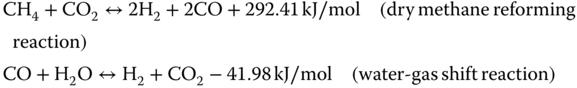
Although, the gasification of biomass is proven to be a fuel for small-scale power plants and heat generation, gasification is yet to be optimized to be technically and economically viable on a larger scale. Since biomass gasification takes place at lower temperatures than biomass combustion, it reduces potential ash-related problems. However, gasification in power generation plant operations are more complex than combustion, and the processes are more sensitive to operating parameters. Most biomass gasification applications demonstrated to date for electric power have power output less than 10 MW [87]. Biomass is also being investigated for co-gasification with coal to reduce fossil-based CO2 emissions. Analysis of IGCC oxy-co-gasification of straw and coal have shown that up to 10% biomass co-gasification in an oxygen-blown entrained flow gasifier was technically feasible [88, 89]. Low heating value clean syngas is suitable for use in internal combustion engines, gas turbines, or other applications requiring a high quality gas. The clean gas mixture can also be utilized in microturbine systems and fuel cells. Fuel cells can utilize the hydrogen fraction of syngas with oxygen to generate electricity and heat in the presence of an electrically conductive electrolyte medium. In addition, the carbon monoxide and methane fractions of the syngas can be converted into hydrogen via dry reforming and water gas shift reactions [84, 90–93]:
Fischer–Tropsch (FT): Biomass Gasification for Advanced Liquid Fuels Manufacturing
Biomass gasification end products of syngas can be converted into various long-chain hydrocarbons to displace fossil-based counterparts. The conversion reaction is widely known as the Fischer–Tropsch (FT) reaction, which was developed originally for coal gasification into liquid fuels [94, 95]:
Liquid hydrocarbons such as biomass-based diesel, kerosene, and gasoline production can be optimized by temperature, pressure, and ratio of H2 to CO. The desired ratio should be close to 2 : 1, and sometimes water gas-shift reaction can be performed to achieve the desired H2 to CO ratios. Cobalt is the widely used catalyst for FT conversions at pressures of 20–40 bar and temperatures between 180 and 250 °C [84, 96].
Syngas from biomass gasification can be converted into ethanol, methanol, and dimethyl ether (DME) as alternative advanced fuels. In addition, syngas can also be chemically and biologically converted into bio-based products including organic acids, alcohols, and polyesters [84].
8.3.2.2.3 Pyrolysis
The term pyrolysis refers to heating of materials in the absence of an oxidizing agent, causing thermal decomposition of polymer structures into smaller molecules. Pyrolysis reactions occur at lower temperatures of 400–600 °C compared with 800–1200 °C in gasification reactions. Pyrolysis conversion yields condensable vapors that subsequently produce liquid products, noncondensable gases (H2, CO, CO2, CH4, and light hydrocarbons), and solid char [97–99]. The reactor types and operating conditions impact the yields of the various products. Depending on the heating rate, pyrolysis reactions can be classified as slow or fast/flash pyrolysis with different yields. Slow heating rates provide higher char yields because slow heating and longer residence time in a reactor results in slow decomposition. In fast pyrolysis, the rapid heat transfer and short residence times produce higher percentages of liquid products. Both types of reaction conditions also generate noncondensable gaseous products such as C1–C4 hydrocarbons. Biomass pyrolysis is emerging as a thermochemical technology that has the potential to serve as a viable conversion pathway of sustainable biomass into sustainable fuels and chemicals to displace petroleum-based counterparts, bio-char to sequester carbon, and sustainable management for biomass waste. Viable feedstocks for biomass pyrolysis include wood residues (mill residues, sawdust, urban wood, and forest thinning), agricultural residues (i.e., corn stover, wheat straw, rice hulls, sugarcane and sorghum bagasse, and low moisture animal waste), and energy crops (i.e., switch grass, hybrid poplar, and hybrid willow) [100–102].
8.3.2.2.3.1 Biomass Pyrolysis Basics
Pyrolysis of biomass is a complex process and is influenced by many different reaction parameters. Due to the complex nature of biomass, the fundamentals of pyrolytic decomposition reactions of biomass are still not completely understood. Consequently, a number of pyrolytic studies of biopolymers (lignin, cellulose, and hemicellulose) are being conducted to further understand the mechanisms of biomass pyrolysis [102, 103]. Biomass pyrolysis products are a complex combination of products as a result of the individual pyrolysis processes for cellulose, hemicellulose, and lignin, each of which has its own kinetic characteristics [103]. However, it is not clear that studying the thermal decomposition of a small number of model compounds such as cellulose, hemicellulose, and lignin is sufficient to model the wide range of biomass species existing in nature and in waste biomass. In addition, the complex interactions between different organic and inorganic biomass components have to be considered to understand the detailed decomposition pathways of biomass and wastes [103–105].
Plasma Gasification
Plasma gasification is an emerging technology that can be used to convert waste material and biomass materials into an energy source. Acceptable feedstocks include organic and plastics components of municipal solid waste, textiles, wood, and rubber. In addition, plasma gasification can convert hazardous waste, hospital solid waste and contaminated materials, sewage sludge, and low level radioactive waste. This technology basically is an incomplete oxidation of hydrocarbon components of waste and generation of a combustible such as mixture of carbon monoxide and hydrogen (syngas) and other minor gases [106]. Syngas can be used for either direct power generation or generation of renewable hydrogen or other fuels where applicable. Plasma gasification also results in compaction and vitrification of solid wastes after gasification. This achieved by the melting of inorganic material by high plasma temperatures eliminating voids and binding hazardous metals in a ceramic matrix (e.g., a silicate) with low leach rates.
Plasma occurs in any gas in which at least part of the atoms or molecules are partly or fully ionized [106]. Thermal plasmas are generated either by an electric arc or by a radiofrequency induction discharge. In waste treatment, arc plasmas dominate because they are relatively insensitive to changes in process conditions. High temperature treatment of waste material provides the following:
- Rapid heating and reaction start-up
- High heat and reactant transfer rates
- Smaller installation size for given waste throughput
- Melting of high temperature materials
A typical plasma system for treatment of solid wastes consists of a plasma reactor with collection of the metal and slag at the bottom and a power supply. In order to eliminate fugitive emissions, plasma gasification reactors should be operated under negative pressure. Plasma gasification temperatures may reach to 2000–30 000 °C [106–108].
A number of biomass pyrolysis studies have shown that the pyrolysis reaction may occur as follows [103]:
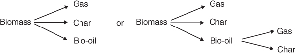
Experimental and modeling research confirms that increased heating rates reduce the char yield during biomass conversion. The distribution of products between bio-oil, char, and gas on a mass basis for slow heating rates is approximately 30%, 35%, and 35%, respectively, whereas under fast/flash heating conditions.,the product distribution can be altered dramatically. Under the fast/flash pyrolysis conditions, bio-oil, char, and gas yields can reach up to 75%, 12%, and 13%, respectively. Pyrolysis oils produced during the decomposition of biomass can decompose further through secondary reactions. In order to maximize the oil yield and reduce the char formation, the reactor design and optimization efforts should minimize the secondary reactions [105, 109–114].
8.3.2.2.3.2 Pyrolysis Reactor Types
Pyrolysis reactions are based on the rate of the pyrolytic conversion, and reactor design can be classified as follows [102, 103, 115, 116]:
- 1. Slow pyrolysis in fixed-bed pyrolysis reactors
- 2. Fast pyrolysis in:
- Fluidized beds, both bubbling and circulating
- Ablative (biomass particles move across hot surface), vacuum, and transported beds without a carrier gas.
Slow pyrolysis in fixed-bed reactors: Slow pyrolysis reactions are generally performed in a fixed-bed reactor where the biomass or waste is placed on a fixed-support bed in the reactor as a batch operation. The reactor is usually heated slowly to final temperatures below 500 °C. Slow heating rates coupled with long solid and gas residence times maximize the yield of char via secondary coking and re-polymerization reactions [98, 115, 116]. Slow pyrolysis is receiving renewed attention due to carbon capture and storage benefits to mitigate climate change. If a feedstock for slow pyrolysis is clean, untreated biomass, the char may also have soil remediation benefits.
Fast/flash pyrolysis: In order to maximize bio-oil yields, efficient heat and mass transfer is necessary during the pyrolysis of materials. Fast pyrolysis occurs during rapid heating (1000–10 000 °C/s) and at high temperatures (∼650 °C) under inert conditions. Increased pyrolysis heating rates and increased surface area result in better heat transfer and increased mass transfer rates. Biomass rapidly depolymerizes to form vapors (a mixture of light hydrocarbons and oxygenates), which ultimately condense to form bio-oil [100, 116]. Also, faster gas feeding rates will reduce vapor residence times in the hot pyrolysis zone, which will minimize secondary cracking and re-polymerization reactions and consequently increase the bio-oil yield. In order to achieve efficient conversion of biomass to liquid products, various types of fast/flash pyrolysis reactors have been developed and tested. In addition to pyrolysis reactor designs, biomass pretreatment for moisture removal, size reduction, and efficient continuous feeding into the pyrolysis zone are important parameters that can be optimized to achieve economically and technically feasible pyrolysis operations.
Fluidized-bed reactors: Biomass conversion into high oil yields requires high heating rates, short vapor residence times, and rapid cooling of the vapors. These characteristics can be achieved in fluidized-bed reactors [117]. Fluidized-bed reactors were developed for the petroleum and chemical process industries and have been in use for more than 50 years [118]. Fluidization technology is a process in which solids are made to behave like a fluid by feeding gas or liquid upward through the solid-filled reactor [119]. Fluidized-bed reactors are used for fast/flash pyrolysis to obtain efficient heat transfer rates from the heated bed material to biomass particles in order to achieve high heat transfer and efficient conversion before biomass particles become charred. The most commonly tested fluidized-bed reactors for biomass pyrolysis are bubbling and circulating-bed reactors. Silica sand is widely used as a fluidized-bed material [120]. Literature has also shown in situ fractional fast pyrolysis with fluidized catalytic beds [121–123].
Bubbling fluidized-bed pyrolysis occurs when the bed material is fluidized by a carrier inert gas fed from the bottom of the reactor to make the bed act as a fluid. The important parameters are appropriate particle size for biomass and the bed fluidizing media. The carrier gas flow rate is important to ensure that the bed material gets fluidized properly but does not get carried away above the free board section of the reactor. Vapor residence times are controlled by the carrier gas flow rate. In order to avoid having the char catalyze vapor cracking reactions, the residence time should be optimized and char should be removed from the bed section as quick as possible [100]. Bubbling fluidized-bed reactors have been reported to be easy to operate and are reliable.
Circulating fluidized-bed pyrolysis reactors provide more efficient heat transfer and shorter residence times. These types of reactors are different from bubbling fluidized beds since there is a secondary reactor following the pyrolysis chamber to combust char and return the hot sands back into the first pyrolysis chamber. These reactors require fine biomass particles since larger biomass particles may get combusted in the secondary reactor, potentially reducing bio-oil yields [100, 115, 118].
Ablative, vacuum, and transported bed pyrolysis reactors: Ablative pyrolysis reactors are designed to convert larger particle size (i.e., 2 cm) biomass into bio-oils. Vacuum pyrolysis reactors were developed to achieve a slow pyrolysis process with higher liquid yields by avoiding secondary cracking reactions. Transported bed reactors do not require a carrier gas since biomass and sand are fed from the bottom of a cone reactor and spin upward to the top of the reactor. Literature reports scalability issues and mechanical problems with this type of pyrolysis reactors. These reactors have been tested at smaller sizes and proved to be unscalable [115, 118, 124].
Fractional catalytic pyrolysis: Biomass feedstocks are composed of structural (cellulose, hemicellulose, and lignin) and nonstructural (extractive) components that have distinct chemical properties [119]. The literature suggests that selectively converting biomass components to end products is possible through fractional catalytic pyrolysis [97, 118, 119]. Fractional pyrolysis is defined as a selective in situ conversion of biopolymers into desired fuels and chemicals without going through secondary separation and upgrading processes. Zeolite catalysts are widely tested catalysts for fractional pyrolysis to generate stable pyrolysis oils with minimal re-polymerization reactions and can potentially be processed in a conventional petroleum refinery [97, 118, 119].
Bio-oil from biomass pyrolysis: Bio-oils via pyrolysis can be produced from a variety of biomass feedstocks including forest and agricultural residues (i.e., bagasse, rice straw, and hulls) and dedicated energy crops (i.e., switch grass, aspen, poplar). The bio-oil yield, based on the feedstock and conversion technology, is in the range of 70–90% by weight. Feedstock with high lignin content, such as bark, may yield lower amounts of bio-oil in the range of 60–65%. Bio-oils have long been considered an alternative to petroleum-based fuels. However, since pyrolysis causes bond cleavage and produces small fragments of biomass polymers, most of the original oxygen in the biomass feedstock is retained as oxygenated compounds in the bio-oil [116, 121, 124, 125]. Bio-oil usually contains 45–50% weight oxygen, depending on the moisture level of the feedstock. Also, most bio-oil analyses show that bio-oils appear to be acidic with a pH of 2.0–3.0 [116, 126–128]. The chemistry of bio-oils can be tailored by changing thermal conditions and using catalytic treatments that influence characteristics of end products. High temperatures can increase the severity of cracking, which may result in lower molecular weight liquids and increased gas products. Higher temperatures also cause dehydrogenation/aromatization reactions to take place, resulting in higher levels of PAH. Both the reaction conditions and catalyst properties are critical in maximizing the desired product selectivity. Research suggests that high heating rates and high catalyst to feed ratio favor aromatic production over coke formation [129]. Fast pyrolysis appears to be a viable technology for producing olefins and aromatic monomers from carbohydrates if the reaction conditions are optimized [100, 115, 128]. Recent research also suggests that converting biomass and its components to BTX and other petroleum-based platform chemicals such as ethylene and propylene is possible by catalytic pyrolysis conversion [130–133]. The advantages include low production costs, high thermal efficiency, and potential CO2 reductions. Various researches on producing pyrolysis oils from agricultural wastes and residues and municipal solid wastes have shown that pyrolysis appears to be a promising technology but requires further research and demonstration [134–138].
8.4 Conclusions
Sustainable biomass-to-bioenergy pathways, including bio-power, bio-heat, advanced biofuels, and bio-based products are emerging as viable alternatives to displace petroleum-based fuels and products. While promoting biomass as a feedstock, it is important to ensure that it does not follow a food-to-fuel pathway that can further stress food resources and negatively impact biodiversity. In addition, new fuels and products should have smaller carbon footprints then the petroleum-based counterparts that they intend to displace. Existing and emerging biomass and waste conversion technologies for power, fuels, and bio-products should be tested, verified, and scaled up from bench to pilot and demonstration scales before full commercial trials are implemented in order to ensure that the technology achieves its energy goals and is economically and environmentally sustainable.
References
- 1. www.UCSUSA.org/clean_energy/our-energy-choices/coal-and other-fossil fuels/.
- 2. The Report of the Brundtland Commission (1987) Our Common Future, Oxford University Press.
- 3. https://sustainabledevelopment.un.org/post2015/transformingourworld.
- 4. Brennan-Tonnetta, M. (2010) A methodology and decision support tool for informing state-level bioenergy policy making: New Jersey biofuels as a case study. Dissertation, Rutgers University, USA.
- 5. FAO (2014) The Water–Energy–Food Nexus: A New Approach in Support of Food Security and Sustainable Agriculture, Food and Agriculture Organization of the United Nations. http://www.fao.org/nr/water/docs/FAO_nexus_concept.pdf.
- 6. Lundy, J. and Bowdish, L. (2015) The Energy–Water–Food Nexus: Insights for the Business Community, U.S. Chamber of Commerce Foundation. https://www.uschamberfoundation.org/report/energy-water-food-nexus-insights-business-community.
- 7. U.S. Department of Energy (2014) The Water–Energy Nexus: Challenges and Opportunities, U.S. Department of Energy. http://energy.gov/sites/prod/files/2014/07/f17/Water%20Energy%20Nexus%20Full%20Report%20July%202014.pdf.
- 8. Fargione, J. et al. (2008) Land clearing and the biofuel carbon debt. Science, 319 (5867), 1235–1238.
- 9. Hertel, T. et al. (2010) Effects of US maize ethanol on global land use and greenhouse gas emissions: estimating market-mediated responses. BioScience, 60, 223–231.
- 10. Searchinger, T. et al. (2008) Use of U.S. croplands for biofuels increases greenhouse gases through emissions from land-use change. Science, 310, 1238–1240.
- 11. Council on Sustainable Biomass Production (2016) Standard for Sustainable Production of Agricultural Biomass, Version 1.0, Council on Sustainable Biomass Production.
- 12. Sanchez, S.T., et al., Accounting for indirect land-use change in the lifecycle assessment of biofuel supply chains, J. R. Soc. Interface 9 (2012), pp. 1105–1119. doi: 10.1098/rsif.2011.0769, http://digitalcommons.unl.edu/bseliska/14
- 13. Silva-Castañeda, L. (2012), A forest of evidence: third-party certification and multiple forms of proof – a case study of oil palm plantations in Indonesia, J. Agric., Food, Human Values Soc. 29 (3), pp. 361–370.
- 14. Vis, M.V., et al. (2008) Sustainability criteria and certification systems for biomass production. Project No. 1386. Biomass Technology Group.
- 15. Bain, R.L. (2006) Thermochemical technologies for conversion of biomass to fuels and chemicals, http://www.docstoc.com/docs/72653060/Conversion-of-Biomass-to-fuels (accessed September 2014).
- 16. Brennan, M., Guran, S., and Specca, D.R. (2014) Assessment of Biomass Energy potential in New Jersey, 2.0, NJAES Publication No. 2014, Rutgers, The State University of New Jersey, New Brunswick, NJ.
- 17. States of Guernsey (2011) A Revised Waste Strategy for Guernsey, Anaerobic Digestion and its Application to Guernsey, SLR, Global Environmental Solutions, http://www.gov.gg/CHttpHandler.ashx?id=1850&p=0 (accessed 24 September 2014).
- 18. Klinkner, B.A. (2014) Anaerobic digestion as a renewable energy source and waste management technology: what must be done for this technology to realize success in the United States. UMass Law Rev., 9, 68–96.
- 19. Ostrem, K. (2004) Greening waste: anaerobic digestion for treating the organic fraction of municipal solid wastes. M.S. thesis. Columbia University, Earth Engineering Center.
- 20. Verma, S. (2002) Anaerobic digestion of biodegradable organic in municipal solid wastes. M.S. thesis. Columbia University, Department of Earth and Environmental Engineering.
- 21. Ahmed, S.I. et al. (2013) Landfill gas and its renewable energy potentials in Johor, Malaysia. Int. J. Emerg. Trends Eng. Dev., 1 (3), pp. 543–558.
- 22. Themelis, N.J., Ulloa, P.A. (2007) Methane Generation in Landfills, Renew. Energy 32, pp. 1243–1257.
- 23. Barker, J.C. (2001) Methane Fuel Gas from Livestock Wastes: A Summary, North Carolina State University Cooperative Extension Service, Raleigh, NC. Publication #EBAE 071-80, www.bae.ncsu.edu/programs/extension/publicat/wqwm/ebae071_80.html.
- 24. Rowse, E.L. (2011) Design of small scale anaerobic digesters for application in rural developing countries. M.S. thesis. University of South Florida, Department of Civil and Environmental Engineering.
- 25. Mintz, M. and Wegrzyn, J. (2009) Renewable natural gas: current status, challenges, and issues. USDOE, Clean Cities, http://www1.eere.energy.gov/cleancities/pdfs/renewable_natural_gas.pdf (accessed 24 September 2014).
- 26. Hobson, J.F. et al. (1997) Volatile methylsiloxanes, in Organosilicon Materials (The Handbook of Environmental Chemistry), vol. 3H (ed. G. Chandra), Springer Verlag, Berlin.
- 27. Rasi, S., Lehtinen, J., Rintala, J. (2010) Determination of organic silicon compounds in biogas from wastewater treatments plants, landfills, and co-digestion plants. Renew. Energy 35, pp. 666–673.
- 28. Wheless, E., and Gary, D. (2002) Siloxanes in Landfill and Digester Gas. Proceedings of the 25th SWANA Landfill Gas Symposium, March 25–28, 2002, Monterey, CA. Solid Waste Association of North America, Silver Springs, MD.
- 29. Pierce, J.L. (2005) Siloxane Quantification, Removal and Impact on Landfill Gas Utilization Facilities. 8th Annual LMOP Conference, January 10–11, http://www.epa.gov/lmop/documents/pdfs/conf/8th/presentation-Pierce.pdf.
- 30. Popat, S.C. and Deshusses, M.A. (2008) Biological removal of siloxanes from landfill and digester gases: opportunities and challenges. Environ. Sci. Technol., 42, 8510–8515.
- 31. Ferreira, A.B. et al. (2012) Tin-catalyzed esterification and transesterification reactions: a review. ISRN Renew. Energy 2012, Article ID 142857, 13pp. doi: 10.5402/2012/142857
- 32. Online Report (2009) Biodiesel Handling and Use Guide, 4th edn, US. Dept. of Commerce. http://www.osti.gov/bridge.
- 33. World Watch Institute (2006) Biofuels for Transportation-Global Potential and Implications for Sustainable Agriculture and Energy in the 21st Century, Summary, World Watch Institute, http://www.worldwatch.org/system/files/EBF008_1.pdf.
- 34. Van Gerpen, J. (2005) Biodiesel processing and production. Fuel Process. Technol., 86, 1097–1107.
- 35. Graboski, M.S. and McCormick, R.L. (1998) Combustion of fat and vegetable oil derived fuels in diesel engines. Prog. Energy Combust. Sci., 28, 125–164.
- 36. McKenna, D., Vaughn, T., Rowen, C., Hesketh, R.P., Bhatia, K.K., Marchese, A.J., Chipko, G., and Guran, S. (2008). Evaluation of emissions and performance of diesel locomotives with B20 biodiesel blends: static test results. RTDF2008-74030. 2008 ASME Rail Transportation Division Meeting, September 24, 2008.
- 37. Tyson, K.S. (2002) Brown Grease Feedstocks for Biodiesel, National Renewable Energy Laboratory, http://www.nrbp.org/pdfs/pub32.pdf.
- 38. Zolezzi, L. and O'Hara, E. (2010) Brown Grease Recovery for Biodiesel. EPA Innovative Energy Management Workshops, February, 2010, http://www.epa.gov/region9/waterinfrastructure/training/energy-workshop/docs/2010/EpaGreaseTrapOperationsHiMauiOahuKauai.pdf.
- 39. Prasad, S. et al (2007) Ethanol as an alternative fuel from agricultural, industrial and urban residues. Resour. Conserv. Recycl., 50, 1–39.
- 40. Binod, P. et al. (2011) Hydrolysis of lignocellulosic biomass for bioethanol production, in Biofuels: Alternative Feedstocks and Conversion Processes (eds A. Pandey, C. Larroche, S.C. Ricke, C.-G. Dussap, and E. Gnansounou), Academic Press, pp. 229–250, ISBN:978-0-12-385099-7.
- 41. Binder, J.B. and Raines, R.T. (2010) Fermentable sugars by chemical hydrolysis of biomass. PNAS, 107, 4516–4521.
- 42. Harris, E.E. (1949) Wood Saccharification Advances in Carbohydrate Chemistry, Academic Press, pp. 153–188.
- 43. Kumar, P. et al. (2009) Methods for pretreatment of lignocellulosic biomass for efficient hydrolysis and biofuel production. Ind. Eng. Chem. Res. 48 (8), pp 3713–3729 (Article ASAP). doi: 10.1021/ie801542g
- 44. Mosier, N.S. et al. (2005) Features of promising technologies for pretreatment of lignocellulosic biomass. Bioresour. Technol., 96, 673–686.
- 45. Himmel, M.E. et al. (2007) Biomass recalcitrance: engineering plants and enzymes for biofuels production. Science, 315, 804–807.
- 46. Jorgensen, H., Kristensen, J.B., and Felby, C. (2007) Enzymatic conversion of lignocellulose into fermentable sugars: challenges and opportunities. Biofuels Bioprod. Bioref., 1, 119–134.
- 47. Yang, B. (2011) Enzymatic hydrolysis of cellulosic biomass. Biofuels, 2 (4), 421–450.
- 48. Suali, E. and Sarbatly, R. (2012) Conversion of microalgae to biofuels. Renew. Sustainable Energy Rev., 16, 4316–4342.
- 49. DOE, U.S. (2010) National Algal Biofuels Technology Roadmap, U.S. Department of Energy, Office of Energy Efficiency and Renewable Energy, Biomass Program. http://www1.eere.energy.gov/bioenergy/pdfs/algal_biofuels_roadmap.pdf.
- 50. Scott, S. et al. (2010) Biodiesel from algae: challenges and prospects. Curr. Opin. Biotechnol., 21, 277–286. www.sciencedirect.com.
- 51. Demirbas, A. and Demirbas, M.F. (2011) Importance of algae oil as a source of biodiesel. Energy Convers. Manage., 52, 163–170.
- 52. Griffiths, M.J. and Harrison, S.T.L. (2009) Lipid productivity as a key characteristic for choosing algal species for biodiesel production. J. Appl. Phycol., 21, 493–507.
- 53. Hu, Q. et al. (2008) Microalgal triacylglycerols as feedstocks for biofuels production: perspectives and advances. Plant J., 54, 621–639.
- 54. Singh, A. et al. (2011) Renewable fuels from algae: an answer to debatable land based fuels. Bioresour. Technol., 102, 10–16.
- 55. Asada, C. et al. (2012) Efficient extraction of starch from microalgae using ultrasonic homogenizer and its conversion into ethanol by simultaneous saccharification and fermentation. Nat. Resour., 3, 175–179.
- 56. John, R. et al. (2011) Micro and macroalgal biomass: a renewable source for bioethanol. Bioresour. Technol., 102, 186–193.
- 57. Demirbas, A. (2010) Use of algae as biofuel sources. Energy Convers. Manage., 51, 2738–2749.
- 58. Demirbas, F. (2011) Biofuels from algae for sustainable development. Appl. Energy, 88, 3473–3480.
- 59. Xu, J. et al. (2012) The production of duckweed as a source of biofuels. Biofuels, 3 (5), 589–601.
- 60. Cui, W. and Cheng, J.J. (2015, ISSN 1435-8603) Growing duckweed for biofuel production: a review. Plant Biol. 17 (Suppl. 1), pp.16–23.
- 61. Zhao, X. et al. (2012) Enzymatic saccharification of duckweed (Lemna minor) biomass without thermophysical pretreatment. Biomass Bioenergy, 47, 354–361.
- 62. Xu, J. et al. (2011) Production of high-starch duckweed and its conversion to bioethanol. Biosyst. Eng., 11, 67–72.
- 63. Jarvis, M.C., Forsyth, W.D., and Henry, J. (1988) A survey of the pectic content of nonlignified monocot cell walls. Plant Physiol. Biochem., 88 (2), 309–314.
- 64. Obaidullah, M. et al. (2012) A review on particle emissions from small scale biomass combustion. Int. J. Renew. Energy Res., 2 (1), 147–159.
- 65. Peterson, D. and Haase, S. (2009) Market Assessment of Biomass Gasification and Combustion Technology for Small- and Medium Scale Applications. Technical report. NREL/TP-7 A2-46190.
- 66. Naik, S.N. et al. (2010) Production of first and second generation biofuels: a comprehensive review. Renew. Sustainable Energy Rev., 14, 578–597.
- 67. Vakkilainen, E., et al. (2013) Large Industrial Users of Energy Biomass. IEA Bioenery, Task 40: Sustainable International Bioenergy Trade, http://www.bioenergytrade.org/downloads/t40-large-industrial-biomass-users.pdf.
- 68. Khan, A.A. et al. (2009) Biomass combustion in fluidized bed boilers: potential problems and remedies. Fuel Process. Technol., 20, 21–50.
- 69. Ruiz, J.A. et al. (2013) Biomass gasification for electricity generation: review of current technology barriers. Renew. Sustainable Energy Rev., 18, 174–183.
- 70. Tissari, J. et al. (2008) Fine particle and gas emissions from the combustion of agricultural fuels fired in a 20 kW burner. Energy Fuels, 22, 2033–2042.
- 71. Johansson, L.S. et al. (2003) Particle emission from biomass combustion in small combustors. Biomass Bioenergy, 25, 435–446.
- 72. McDonald, J.D. et al. (2000) Fine particle and gaseous emission rates from residential wood combustion. Environ. Sci. Technol., 34, 2080–2091.
- 73. Baxter, L. (2005) Biomass-coal co-combution: opportunity for affordable renewable energy. Fuel, 84, 2141–2162.
- 74. Hein, K.R.G. and Bemtgen, J.M. (1998) EU clean coal technology-co-combustion of coal and biomass. Fuel Process. Technol., 54, 159–169.
- 75. Alauddin, Z.A.B.Z. et al. (2010) Gasification of lignocellulosic biomass in fluidized beds for renewable energy development: a review. Renew. Sustainable Energy Rev., 14, 2852–2862.
- 76. Devi, L.M. et al. (2003) A review of the primary measures for tar elimination in biomass gasification processes. Biomass Bioenergy, 24, 125–140.
- 77. Puig-Arnavat, M. et al. (2010) Review and analysis of biomass gasification models. Renew. Sustainable Energy Rev., 14, 2841–2851.
- 78. Pereira, E.G. et al. (2012) Sustainable energy: a review of gasification technologies. Renew. Sustainable Energy Rev., 16, 4753–4762.
- 79. Damartzis, T. and Zabaniotou, A. (2011) Thermochemical conversion of biomass to second generation biofuels through integrated process design: a review. Renew. Sustainable Energy Rev., 15, 366–378.
- 80. Skoulou, V. et al. (2008) Syngas production from olive tree cuttings and olive kernels in a downdraft fixed-bed gasifier. Int. J. Hydrogen Energy, 33, 1185–1194.
- 81. Rauch, R. (2003) Biomass Gasification to Producesynthesis Gas for Fuels and Chemicals. Report for IEA Bioenergy Agreement, Task33, Thermal Gasification of Biomass.
- 82. Nemtsov, D.A. and Zabaniotou, A. (2008) Mathematical modelling and simulation approaches of agricultural residues air gasification in a bubbling fluidized bed reactor. Chem. Eng. J., 143, 10–31.
- 83. Basu, P. (2010), Gasification theory and modelling gasifiers in Gasification Design Handbook, Boston: Academic Press. 10.1016/B978-0-12-374988-8.00005-2 117-165.
- 84. Wang, L. et al. (2008) Contemporary issues in thermal gasification of biomass and its application to electricity and fuel production. Biomass Bioenergy, 32, 573–581.
- 85. Sutton, D. et al. (2001) Review of literature on catalysts for biomass gasification. Fuel Process. Technol., 73, 155–173.
- 86. Bain, R.L. et al. (2005) Evaluation of catalyst deactivation during the catalytic steam reforming of biomass-derived syngas. Ind. Eng. Chem. Res., 44, 7945–7956.
- 87. Ahrenfelt, J. et al. (2013) Biomass gasification cogeneration – a review of state of the art technology and near future perspectives. Appl. Therm. Eng., 50, 1407–1417.
- 88. Valero, A. and Uson, S. (2006) Oxy-co-gasification of coal and biomass in an integrated gasification combined cycle (IGCC) power plant. Energy, 31, 1643–1655.
- 89. Uson, S. et al. (2004) Building operation maps: an effective tool for improving gasifier operation in IGCC power plants. Int. J. Thermodyn., 7 (4), 157–164.
- 90. Hernandez-Pacheco, E. et al. (2005) A cell-level model for a solid oxide fuel cell operated with syngas from gasification process. Int. J. Hydrogen Energy, 30, 1221–1233.
- 91. Iaquaniello, G. and Mangiapane, A. (2006) Integration of biomass gasification with MCFC. Int. J. Hydrogen Energy, 31, 399–404.
- 92. Jurado, F., Cano, A., and Carpio, J. (2004) Biomass based micro-turbine plant and distribution network stability. Energy Conserv. Manage., 45, 2713–2727.
- 93. Karellas, S., Karl, J., and Kakaras, E. (2008) An innovative biomass gasification process and its coupling with microturbine and fuel cell systems. Energy, 33, 284–291.
- 94. Schulz, H. (1999) Short history and present trends of Fischer–Tropsch process. Appl. Catal., 186, 3–13.
- 95. Dry, M.E. (1996) Practical and theoretical aspects of the catalytic Fischer–Tropsch process. Appl. Catal., 138, 319–344.
- 96. Tijmensen, M.J.A. et al. (2002) Exploration of the possibilities for production of Fischer–Tropsch liquids and power via biomass gasification. Biomass Bioenergy, 23, 129–152.
- 97. Bridgwater, A.V. et al (1999) An overview of fast pyrolysis of biomass. Organ. Geochem., 30, 1479–1493.
- 98. Williams, P.T. and Besler, S. (1996) The influence of temperature and heating rate on the slow pyrolysis of biomass. Renew. Energy, 7, 233–250.
- 99. Bridgewater, A.V. and Bridge, S.A., A review of biomass pyrolysis and pyrolysis technologies, A.V. Bridgewater et al. Biomass Pyrolysis Liquids Upgrading and Utilization, ECSC, EEC, EAEC, Brussels and Luxembourg, 1991, 2, 11-91.
- 100. Bond, J.Q. (2014) Production of renewable jet fuel range alkanes and commodity chemicals from integrated catalytic processing of biomass. Energy Environ. Sci. 7, pp. 1500–1523. doi: 10.1039/c.3ee43946e
- 101. Agblevor, F.A. et al. (1995) Fast pyrolysis of stored biomass feedstocks. Energy Fuels, 9, 635–640.
- 102. Wright, M.M., et al. (2010) Techno-Economic Analysis of Biomass Fast Pyrolysis to Transportation Fuels. Technical report. NREL/TP-6A20-46586.
- 103. Couhert, C. et al. (2009) Is it possible to predict gas yields of any biomass after rapid pyrolysis at high temperature from its composition in cellulose, hemicellulose and lignin? Fuel, 88 (3), 408–417.
- 104. Couhert, C. et al. (2009) Failure of the component additivity rule to predict gas yields of biomass in flash pyrolysis at 950 °C. Biomass Bioenergy, 33, 316–326.
- 105. van de Weerdhof, M.W. (2010) Modeling the pyrolysis process of biomass particles. Master thesis. Eindhoven University of Technology, http://w3.wtb.tue.nl/fileadmin/wtb/ct-pdfs/Master_Theses/Marcovandeweerdhof.pdf.
- 106. Arena, U. (2012) Process and technological aspects of municipal solid waste gasification: a review. Waste Manage., 32, 625–639.
- 107. Morin, S. et al. (2012) Two stage fluid bed plasma gasification process for solid waste valorisation; technical review and preliminary thermodynamic modelling of sulphur emissions. Waste Manage., 32, 676–684.
- 108. Murphy, A.B. and Heberlein, J. (2008) Thermal plasma waste treatment. J. Phys. D Appl. Phys., 41, 1–20.
- 109. Thunman, H. and Leckner, B. (2002) Thermal conductivity of wood-models for different stages of combustion. Biomass Bioenergy, 23, 47–54.
- 110. Di Blasi, C. (1996) Heat, momentum and mass transport through a shrinking biomass particle exposed to thermal radiation. Chem. Eng. Sci., 51, 1121–1132.
- 111. Di Blasi, C. et al. (1999) Product distribution from pyrolysis of wood and agricultural residues. Ind. Eng. Chem. Res., 38, 2216–2224.
- 112. Broido, A. and Nelson, M.A. (1975) Char yield on pyrolysis of cellulose. Combust. Flame, 24, 263–268.
- 113. Bridgwater, A.V. et al. (2001) An overview of fast pyrolysis, in Progress in Thermochemical Biomass Conversion (ed. A.V. Bridgwater), Blackwell Science, Oxford, pp. 977–997.
- 114. Agblevor, F.A. et al. (1994) Inorganic compounds in biomass feedstocks: their role in char formation and effect on the quality of fast pyrolysis oils, in Proceedings of Biomass Pyrolysis Oils Properties and Combustion Meeting, September 26–28, 1994, Estes Park, CO, NREL-CP-430-7215 (ed. T.A. Milne), NREL, Golden, CO, pp. 77–89.
- 115. Lede, J. (2013) Biomass fast pyrolysis reactors: a review of a few scientific challenges and of related recommended research topics. Oil Gas Sci. Technol., 68, 801–814.
- 116. Mohan, D. et al. (2006) Pyrolysis of wood/biomass for bio-oil: a critical review. Energy Fuels, 20, 848–889.
- 117. Aho, A. et al. (2008) Catalytic pyrolysis of woody biomass in a fluidized-bed reactor: influence of zeolite structure. Fuel, 87, 2493–2501.
- 118. Ringer, M., et al. (2006) Large-Scale Pyrolysis Oil Production: A Technology Assessment and Economic Analysis. Technical report. National Renewable Energy Laboratory, NREL/TP-510-37779.
- 119. Kunii, D. and Levenspiel, O. (1991) Fluidization Engineering, 2nd edn, Butterworth-Heinemann, Stoneham.
- 120. Knutsson, P., et al. (2014) Effect of Bed Materials Mixing On the Observed Bed Sintering. 11th International Conference on Fluidized Bed Technology, CFB 2014; Beijing; China; 14 May 2014 through 17 May 2014, 655–660.
- 121. Agblevor, F.A. et al. (2010) Production of stable biomass pyrolysis oils using fractional catalytic pyrolysis. Energy Fuels, 24, 4087–4089.
- 122. Agblevor, F.A. and Besler-Guran, S. (2002) Fractional pyrolysis of biomass for high-valued products. Fuel Chem. Div. Prepr., 47, 374–375.
- 123. French, R. and Czernik, S. (2010) Catalytic pyrolysis of biomass for biofuels production. Fuel Process. Technol., 91, 25–32.
- 124. Bridgwater, A.V. (2003) Renewable fuels and chemicals by thermal processing of biomass. Chem. Eng. J., 91, 87–102.
- 125. Oasmaa, A. and Czernik, S. (1999) Fuel quality of biomass pyrolysis oils-state of the art for the end users. Energy Fuels, 13, 914–921.
- 126. Piskorz, J. et al. (1998) Fast pyrolysis of sweet sorghum and sweet sorghum bagasse. J. Anal. Appl. Pyrolysis, 46, 15–29.
- 127. Demirbas, A. (2004) Effect of initial moisture content on the yields of oily products from pyrolysis of biomass. J. Anal. Appl. Pyrolysis, 71, 803–815.
- 128. Garcia-Perez, M. et al. (2006) Multiphase structure of bio-oils. Energy Fuels, 20, 364–375.
- 129. Carlson, T.R. et al. (2009) Aromatic production from catalytic fast pyrolysis of biomass-derived feedstocks. Top. Catal., 52, 241–252.
- 130. Carlson, T.R. et al. (2008) Green gasoline by catalytic fast pyrolysis of solid biomass derived compounds. Chem. Sus. Chem., 1, 397–400.
- 131. Sorensen, C. M., et al. (2016) Processes for converting biomass to BTX with low sulfur, nitrogen and olefin content via a catalytic fast pyrolysis reactor. Patent Application, 20,160,002,544.
- 132. Elfady, A.M. et al. (2016) Highly selective BTX from catalytic fast pyrolysis of lignin over supported mesoporous silica. Int. J. Biol. Macromol., 16 (91), 278–293.
- 133. Vispute, T.P. et al. (2010) renewable chemical commodity feedstocks from integrated catalytic processing of pyrolysis oils. Science, 330, 1222–1227.
- 134. Putun, A.E. et al. (2005) Fixed-bed pyrolysis of cotton stalk for liquid and solid products. Fuel Process. Technol., 86, 1207–1219.
- 135. Demirbas, A. et al. (2004) Effects of temperature and particle size on bio-char yield from pyrolysis of agricultural residues. J. Anal. Appl. Pyrolysis, 72, 243–248.
- 136. Reed, A.R. and Williams, P.T. (2004) Thermal processing of biomass natural fibre wastes by pyrolysis. Int. J. Energy Res., 28, 131–145.
- 137. Buah, W.K. et al. (2007) Characterization of products from pyrolysis of municipal solid waste. Trans. IChemE, 85 (B5), 450–457.
- 138. Faravelli, T. et al. (2001) Thermal degradation of polystyrene. J. Anal. Appl. Pyrolysis, 60, 103–121.
Further Reading/Resources
- Black & Veatch (2008) Advanced Biopower Technology Assessment prepared for Massachusetts Division of Energy Resources.
- Davis, R., Tao, L., Tan, E.C.D., Biddy, M.J., Beckham, G.T., Scarlata, C., Jacobson, J., Cafferty, K., Ross, J., Lukas, J., Knorr, D., and Schoen, P. (2013) Process Design and Economics for the Conversion of Lignocellulosic Biomass to Hydrocarbons: Dilute-Acid and Enzymatic Deconstruction of Biomass to Sugars and Biological Conversion of Sugars to HydrocarbonsPDF. NREL report no. NREL-TP-5100-60223, 147 pp.
- Dutta, A., Dowe, N., Ibsen, K.N., Schell, D.J., and Aden, A. (2010) Economic comparison of different fermentation configurations to convert corn stover to ethanol using Z. mobilis and Saccharomyces. Biotechnol. Prog., 26 (1), 64–72. NREL report no. JA-510-45764 (January 2010).
- Dutta, A. and Phillips, S.D. (2009) Thermochemical Ethanol via Direct Gasification and Mixed Alcohol Synthesis of Lignocellulosic Biomass PDF. NREL report no. TP-510-45913,144 pp.
- Dutta, A., Talmadge, M., Hensley, J., Worley, M., Dudgeon, D., Barton, D., Groendijk, P.. Ferrari, D., Stears, B., Searcy, E.M., Wright, C.T., Hess, J.R. (2011) Process Design and Economics for Conversion of Lignocellulosic Biomass to Ethanol: Thermochemical Pathway by Indirect Gasification and Mixed Alcohol Synthesis PDF. NREL report no. TP-5100-51400, 187 pp.
- French, R. and Czernik, S. (2010) Catalytic pyrolysis of biomass for biofuels production. Fuel Process. Technol. 91(1), pp. 25–32.
- Granatstein, D., et al. (2009) Use of Biochar from the Pyrolysis of Waste Organic Material as a Soil Amendment. Washington State University, Sustaining Agriculture and Natural Resources, C0800248.
- Humbird, D., Davis, R., Tao, L., Kinchin, C., Hsu, D., Aden, A., Schoen, P., Lukas, J., Olthof, B., Worley, M., Sexton, D., and Dudgeon, D. (2011) Process Design and Economics for Biochemical Conversion of Lignocellulosic Biomass to Ethanol: Dilute-Acid Pretreatment and Enzymatic Hydrolysis of Corn StoverPDF. NREL report no. TP-5100-47764, 147 pp.
- Wright, M., et al. (2010) Techno-Economic Analysis of Biomass Fast Pyrolysis to Transportation Fuels. Technical report. NREL/TP-6A20-46586.