
Chapter 14
Separation of Butanol, Acetone, and Ethanol
Di Cai, Song Hu, Peiyong Qin and Tianwei Tan
Acetone–butanol–ethanol (ABE) fermentation is one of the oldest industrial fermentation styles, the second largest fermentation process in the early of twentieth century [1, 2]. Unfortunately, ABE fermentation suffered from the technical bottlenecks of severe product inhibition of butanol, leading to the low butanol concentration in the fermentation broth with low ABE productivity [3–5]. After 1950s, with the prosperous of petrochemical industry, bio-based butanol lost its competitiveness to the rising synthesis of butanol by petrochemical routes because of the increasing cost of raw materials and the relatively high cost of the purification processes from the low titer ABE fermentation broth [6–8].
In current years, with the anxious of energy security, the petroleum supply, and the climate change, ABE fermentation has regained the attention of researchers because the solvent product, biobutanol, is considered to be a biofuel candidate with many superiorities compared with bioethanol [9–11]. In facing the bottlenecks of butanol toxicity and low productivity of the bacteria, genetic and metabolic effort as well as the evolution engineering method to improve the tolerance of butanol has been taken [12–16]. However, in most case of butanol fermentation processes, concentrations of butanol in the fermentation broth are between 10 and 25 g/l, resulted in the energy-intensive and costly downstream processes [17, 18]. As a result, for every 1 t of the solvent product, approximately 12 t of steam is required [19].
To enhance the biobutanol concentration and reduce the inhibition of butanol to the bacteria, fermentation integrated with solvent recovery is an attractive way [10]. Technologies of gas stripping, liquid–liquid extraction, pervaporation, perstraction, and adsorption have been wildly used in integrated ABE fermentation processes. In facing the advanced butanol fermentation application in industrial scale, the ideal integrated process calls for microbial friendly, non-fouling as well as enhancing productivity of butanol [20].
14.1 Gas Stripping
Gas stripping is an easy-to-operate technique for recovering butanol (acetone and ethanol) from fermentation broth [11]. As illustrated in Figure 14.1, a typical gas stripping process can be either integrated with the fermentor or the individual stripping column [21]. During the conventional gas stripping process, nitrogen or gases (CO2 and H2 from the metabolism of strains) is used as the carrier gas to maintain the anaerobic condition [22, 23]. When operated, the oxygen free gases are bubbling the fermentation broth. During the process, ABE solvents, the volatile constituents, are enriched in the carrier gases because of the higher partial pressure than the vapor [24]. Then, a condenser is followed to cool the gas with ABE solvents concentrated and separated from the fermentation broth [25, 26]. The gas flow during gas stripping process can be either in single-pass scenario, where the gas passes though the condenser is released into the open air, or recycled scenario, where the gas after the condenser is reused. Thus, the process in the recycled scenario is a closed system with more solvent products captured than that in the single-pass mode.

Figure 14.1 Schematic diagram of the gas stripping process. (a) Recycled scenario (b) Single-pass scenario.
In the integrated process with ABE fermentation, gas stripping offers a number of advantages, which mainly include easy to operate and no fouling to the fermentation system [5, 24]. More importantly, during the process, only the volatiles with no solids are removed from the fermentor. That is, gas stripping provides a harmless way to overcome the cell toxicity of butanol from the fermentation broth without any inhibition to the culture. However, drawbacks are also obvious. During the process of ABE solvents condensation, not only would the volatility compounds in the mixture gas be transferred into the liquid phase by condensation, but the water fraction, unfortunately, would also be condensed.
Several important factors should be considered when using gas stripping technique in ABE system. According to the principle of the gas stripping technology, the partial pressures of the components in gas phase are the key factor to the selectivity of the solvents. As it shows in Eq. (14.1),
the partial pressure of component i(Pi) in the gas phase is mainly determined by several factors, where yi and xi are referred to the mole fractions of component i in gas and liquid phase, respectively, and Ptotal and Psat are the total pressure of the gas phase and the saturated vapor pressure of i in the temperature operated [24]. Furthermore, other factors, including bubble size, interfacial contact area, contact time, cooling temperature, and stripping rate, are all proved to be the selectivity of volatility compounds [1, 22, 27]. In general, with the cooling temperature getting lower, the condenser efficiency would get higher. However, with the temperatures get lower, a higher percentage of water would be condensate. As for the effect of stripping rate, Ezeji et al. [1] defined it as the Eq. (14.2):
where Rs was the stripping rate and Cs was the concentration of solvents in the aqueous. Ksa was defined as the stripping rate constant.
To increase the gas stripping efficiency, minimize the bubble in order to increase the interfacial area and the enhancement of gas stripping rate are the two keys of the performance. Because the aforementioned factors might influence the performance of gas stripping process, it is more or less difficult to calculate the real selectivity by kinetic models. On average, the selectivity of butanol on various studies ranges from 11 to 15.
Given it sample to operate, gas stripping has been coupled with many ABE fermentation processes in current years. With the in situ ABE separation, the ABE productivity and yield could increase. More importantly, a high titer of ABE solvent is separated as well, which more or less contributes to decrease the butanol purification cost [18, 28]. Since the integration processes can remove the product simultaneously, concentrated substrate utilized by microorganism is achievable. Comparing with the batch and continuous ABE fermentation, fed-batch mode is always integrated because of the high concentration of substrate utilized and no toxicity to the strains. Table 14.1 summarizes performance of various integrated gas stripping processes.
Table 14.1 Comparison of ABE fermentations with integrated gas stripping for online butanol recovery
| Fermentation type | Mode | Gas stripping type | Feedstock | Strain | Solvents in condensate (g/l) | ABE yield (g/g) | ABE productivity (g/l h) | References | |
| Butanol | ABE | ||||||||
| Butanol | ABE | ||||||||
| Batch | Free cells | Intermittent | Glucose | C. beijerinckii P260 | 35.9 | 45.9 | 0.46 | 0.34 | [29] |
| Immobilization | Continuous | Glucose | C. acetobutylicum JB 200 | 175.6 | 227 | 0.4 | 0.66 | [30] | |
| Immobilization | Continuous | Glucose | C. acetobutylicum ABE 1201 | 97.3–166.8 | 155.7–255.6 | 0.4 | 0.36 | [31] | |
| Fed-batch | Immobilization | Intermittent | Glucose | C. acetobutylicum JB 200 | 150.5 | 195.9 | 0.36 | 0.53 | [27] |
| Immobilization | Intermittent | Glucose | C. acetobutylicum B 3 | 150 | 200 | 0.36 | 0.61 | [32] | |
| Immobilization | Intermittent | Glucose | C. acetobutylicum ABE 1201 | 140–175 | 210–255 | 0.34 | 0.38 | [31] | |
| Free cells | Continuous | Cornstarch | C. beijerinckii BA 101 | 38.3–99.6 | 0.36 | 0.59 | [33] | ||
| Immobilization | Continuous | Cassava bagasse | C. acetobutylicum JB 200 | 100–160 | 155–210 | 0.37 | 0.53 | [21] | |
| Immobilization | Continuous | Glucose | C. acetobutylicum ABE 1201 | 115 | 180 | 0.38 | 1.15 | [31] | |
| Immobilization | Continuous | Sorghum juice | C. acetobutylicum ABE 1201 | 112.9 | 166.5 | 0.41 | 0.53 | [34] | |
Based on the literature summarized in Table 14.1, although gas stripping could increase the productivity and sugar utilization in ABE fermentation, the selectivity of butanol is relatively low. It was reported that butanol concentration higher than 7.7 wt% would generate the phase separation, which would also significantly simplify the butanol purification process and reduce energy input for butanol recovery [21, 27]. Therefore, only a few of integration processes of gas stripping would achieve this goal. And most of the processes are energy intensive [27]. Depending on the process conditions, total energy required for gas stripping and further distillation was calculated from 14 to 31 MJ/kg, which is at least half the energy content of butanol (36 MJ/kg) [35, 36]. And only approximately 2.6 MJ/kg of butanol is required when the butanol concentration is higher than 15% (w/v) [24], which demonstrated that higher butanol concentration in the condensate is encouraged. To achieve this goal, immobilized ABE fermentation coupled with two-stage gas stripping was studied [30, 37]. After the first stage of gas stripping, about 227 g/l of ABE was generated in the condensate. And in the end of the second stage of gas stripping, a highly concentrated product containing 420.3 g/l (532.3 g/l of total ABE) was obtained. Thus, the high-titer butanol could be purified with less energy cost in the following distillation system [30].
Compared with the traditional in situ gas stripping separation processes, another strategy is to establish a vacuum-based fermentation system. As it shows in Figure 14.2, vacuum pump is connected with the fermentor and the gases in the fermentor is pumped out continuously and condensed so that separated ABE solvents and contribute to the enhancement of fermentation. Using this method, the substrate was completely utilized and the productivity of solvents was getting higher [29]. However, the vacuum fermentation process is not competitive with the conventional gas stripping method in both ABE yield and concentration.
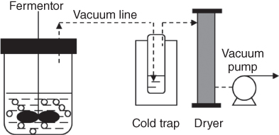
Figure 14.2 Schematic diagram of acetone–butanol–ethanol (ABE) production recovery by vacuum.
As for improvements of gas stripping technique, higher selectivity and lower energy requirements are demanded, as a solution, design, and fabrication efficiency processes with mass and energy integration schemes are needed [24, 28]. Besides, the energy required in cooling and heating the stripping gases during the cycle should be considered [28].
Anyway, up to now, gas stripping technique is suggested to be the most economical and effective technology for in situ ABE solvents recovery, even though it has not been widely used in commercial processes [5].
14.2 Liquid–Liquid Extraction
Liquid–liquid extraction is a kind of method used to separate ABE solvents from fermentation broth via the principal of different solubility between the oil phase and the water phase. Extractant is mixed with the fermentation broth, and then, solvent products are transported from the fermentation broth into the extractant and carried out simultaneously, thus maintaining low concentration of butanol in the fermentation broth in order to reduce the solvents toxicity of clostridia [7, 20, 24]. The mixture of extractant and ABE solvents is then pumped into the distillation tower and the extractant liquid was reused [11].
Even though liquid–liquid extraction associated with separation systems always provides high selectivity and efficiency, however, the critical problems of the extractant toxicity to the bacteria should be overcome [11]. Besides, the selectivity, distribution coefficient, and immiscible and phase separations from aqueous solution, the cost and availability should be also concerned when choosing the suitable extractant to recover ABE solvents via liquid–liquid extraction [24, 38]. Under these concerns, performance and toxicity of different types of extractants were summarized previously (Table 14.2) [39, 40]. Besides, it was also reported that the organic solvents including poly(propylene glycol), n-decanol, dibutyl-phthalate, 2-ethyl-1-bexanol, oleyl alcohol, hexadeane, and glyceryl tributyrate can be used as extractant for ABE solvents extraction and separation because of the high partition coefficients and low toxicity [41–49]. Among the different types of extractants, oleyl alcohol is the most commonly used, which suggested being the most effective candidate in ABE solvents extraction and having no harm to the microorganisms [46–49]. Additionally, compared with the traditional single organic-based extraction system, solvent mixtures could also provide a high substrate consumption rate and ABE solvents productivity when coupled with fermentation in order to generate a high partition coefficient and low toxicity [48, 50]. Except petrochemical-based extractions, biodiesel from biomass resources is also maintained to be a good extractant [51, 52]. Since biodiesel and butanol are all suggested to be the biofuel candidate, butanol–biodiesel mixture could be utilized as diesel fuel directly, which is proved to have a properties enhancement attribute to the higher cetane number and a lower cold filter plugging point than traditional diesel [52].
Table 14.2 Solvent extractants for butanol recovery by liquid–liquid extraction [39, 40]
| Solvent | Buthanol selectivity | Distribution coefficient | Toxicity |
| Butyl acetate | — | ∼3 | Non toxic |
| Butyl stearate | 1.2 | — | Non toxic |
| Corn oil | 440 | 0.7 | Non toxic |
| Decane | 4300 | 0.3 | Non toxic |
| Decanol | 200 | 8 | Toxic |
| Dibutyl adipate | 5 | 3.6 | Toxic |
| Dibutyl maleate | 3 | 2 | Toxic |
| Dibutyl phthalate | 3 | 1.4 | Non toxic |
| Dodecane | 2900 | 0.3 | Non toxic |
| Dodecanol | 140 | 6 | toxic |
| Ethyl laurate | 7 | 1.7 | Non toxic |
| Ethyl oenanthate | 4 | 2 | Non toxic |
| Ethyl oleate | 6 | 1.3 | Non toxic |
| Ethyl stearate | 7 | 0.8 | Non toxic |
| Gasoline | — | 0.3 | Non toxic |
| Heptane | 3300 | 0.5 | Non toxic |
| Heptanol | 180 | 11 | Toxic |
| Hexane | 2700 | 0.5 | Non toxic |
| Hexanol | 160 | 12 | Toxic |
| Hexyl acetate | 5 | 3.6 | Non toxic |
| Isophytol | — | 3.2 | Non toxic |
| Isopropyl myristate | 7 | 1.4 | Non toxic |
| Methyl laurate | 7 | 1.8 | Non toxic |
| Methyl oleate | 6 | 1.3 | Non toxic |
| Octane | 4100 | 0.3 | Non toxic |
| Octanol | 130 | 10 | Toxic |
| Oleic acid | 6 | 3.9 | Non toxic |
| Oleyl alcohol | — | 3.6 | Non toxic |
| Olive oil | 470 | 0.7 | Non toxic |
| Sesame oil | 220 | 0.3 | Non toxic |
| Tributyl citrate | 2 | 2.4 | Non toxic |
| Tributyrin | — | — | Non toxic |
Compared with the extractants based on long-chain organic compounds, in recent years, ionic liquid is also claimed to be the potential extractant for recovery ABE solvents from fermentation broth [24]. Adjusted by manipulation the anions and cations structure and the water miscibility and hydrophobicity of ionic liquid are improved so that extraction butanol from fermentation broth [53].
To avoid the inhibition of extractants to the culture of ABE fermentation, another strategy is using a membrane to separate the fermentation broth and extractant into two phases, and butanol could exchanged between the two immiscible phases, namely perstraction [11, 18, 24]. Since there are no direct contacts between the two phases, the problems of the extractant toxicity, phase dispersion, and emulsion are solved [18]. However, drawbacks of the technology are obvious. Limitations of fermentation intermediate product to extractant losses, expensive to operate, membrane fouling, and lack simplicity all lead to the restriction of perstraction technique [20]. As for its application, about 136.58 g/l and 33–57.8 g/l of butanol were obtained via the integrated process in batch and fed-batch modes, respectively [54, 55].
Generally, the liquid–liquid separation process is easy to operate. Currently, based on the in situ liquid–liquid separation process, the fermentation and separation processes (in situ extraction recovery) was further cascaded with chemical process to produce biochemicals and advanced biofuels under the concept of biorefinery. Anbarasan et al. [42] suggested a new integrated process for chemical catalyze the bio-based ABE product. After fermentation, ABE solvents were extracted by extractant and the organic phase was then pumped into the distillation system. After that, the pure ABE solvents were catalyzed by Pd/C-K3PO4. By operation of the cascade process, higher alkylated products and alcohol products were generated. Besides, van den Berg et al. [43] also provide a cascade process based on lipase catalysis, which further converted the butanol production to esters. In this process, ABE solvents were separated by hexadecane.
14.3 Adsorption
Compared with other separation methods, as shown in Figure 14.3, adsorption is the most energy-efficient separation technique, where target products are firstly absorbed on the surface of absorbent from fermentation broth, and then desorbed and collected. Due to the selective adsorption property of the adsorbent, concentrated products can be obtained. Moreover, the absorbents also possess the selective sorption for acetone and alcohol. The schematic diagram of ABE separation and concentration from fermentation broth is shown in Figure 14.4.

Figure 14.3 A comparison of energy requirement to separate ABE from fermentation broth using various energy-efficient techniques. SS, steam stripping distillation; GS, gas stripping; Perv, pervaporation; Ext, liquid–liquid extraction; Ad, adsorption onto silicalite [36].

Figure 14.4 A schematic diagram of ABE separation and concentration from fermentation broth using adsorbent.
In the process of adsorption, many factors need to be considered, such as pore size of adsorbent, specific surface area of adsorbent, adsorption rate, adsorption capacity, ease of desorption, selectivity for desired product, reuse of adsorbent, and the cost [28]. The adsorptions of macromolecules were prevented by the small pores on the surface of absorbents. Moreover, the specific surface area of the adsorbent immediately impacts the number of hydrophobic adsorption “sites” available for the biofuel [56, 57]. The adsorption rate and capacity also determined the adding amount of adsorbent, wherein the removal rate of biofuel molecules by adsorbent must be equal to or greater than their rate of biosynthesis to keep the concentration below the inhibitory range [58].
For designing a complete recovery process, desorption as a crucial process is also needed to be taken into account. Generally, adsorbed species are desorbed by one of the following methods: (i) pressure swing operation, (ii) purge gas stripping, (iii) displacement desorption, and (iv) thermal swing operation [59]. Considering the process cost, recovery by pressure swing and purge gas stripping is impractical at the plant level due to the very low vapor pressure of butanol. Displacement desorption is regarded as a possible option by introducing new displacers to replace butanol. After displacement, however, removal of the displacement agent is needed to regenerate the adsorbents. By comparison, thermal swing is operated by increasing temperature to produce a concentrated butanol solution and without any additional operations. Regeneration of an adsorbent by using thermal swing is most widely used in industrial applications. Besides, in the recent developments, Águeda et al. recovered 98% (w/w) butanol from 0.5% to 2% (w/w) dilute aqueous solutions by using adsorption–drying–desorption (ADD) process. In their studies, the adsorption column was dried by heated air flow at low temperatures (50–70 °C), and desorption process was operated at high temperatures (130–150 °C) with heated air flow [60].
As listed in Table 14.3, a number of adsorbents, such as zeolites, activated carbons, and polymeric resins, have been used to adsorb butanol from aqueous solutions and fermentation broth. However, limitations exist in the use of such adsorbents, especially about their ease of regeneration and continued reuse. For instance, polymeric resins have low thermal stability of pore structures, which can lead to a decrease in reusable performance due to the high temperature for adsorption. Conversely, although zeolites possess high thermal stability [59], hydrothermal instability, which becomes apparent at temperatures as low as 70 °C, is found in hydrophobic zeolites with high silica content due to the reaction between adsorbed components and silica [60]. Moreover, though thermal and chemical instabilities have never been found in activated carbons, initial reports showed that activated carbons have only marginal performance for the separation of biofuel alcohols [72].
Table 14.3 Some results of butanol adsorption by different adsorbents
| Adsorbent | Feed solution | Initial butanol concentration in solution (g/l) | Eq. butanol concentration in solution (g/l) | Butanol adsorption capacity (mg/g) | Temperature (°C) | References |
| Activated carbon F-400 | Binary | 15 | 1.4 | 185 | Room temperature | [61] |
| Activated carbon F-400 | Binary | 15 | 302 | Room temperature | [62] | |
| Activated carbon F-600 | Binary | 15 | 1.75 | 136 | Room temperature | [61] |
| Zeolite NaY | Binary | 10 | 4.6 | 77 | Room temperature | [61] |
| Zeolite ZSM-5 | Binary | 15 | 4.9 | 104 | Room temperature | [61] |
| Silicalite | Binary | 15 | 3.9 | 111 | Room temperature | [61] |
| L15 macroporous polymer resin | Binary | — | 2 | 250 | 37 | [63] |
| KA-I resin | Binary | — | 10 | 144 | 25 | [64] |
| KA-I resin | Ternary | 30 | 22.5 | 132 | 10 | [65] |
| HP20 Styrene-co-divinylbenzene | Binary | 15 | — | 58 | 37 | [66] |
| HP2MG polymethacrylate | Binary | 15 | — | 31 | 37 | [66] |
| Optipore L493 Styrene-co-divinylbenzene | Binary | 15 | — | 80 | 37 | [66] |
| SP850 Styrene-co-divinylbenzene | Binary | 15 | — | 76 | 37 | [66] |
| ZIF-8 | Binary | 40 | — | 300 | 27 | [67] |
| ZIF-8 | Ternary | 20 | — | 227 | 27 | [67] |
| Core–shell Ag@ZIF-8 | — | 5 | — | 232 | Room temperature | [68] |
| CBV28014 (ZSM-5) | Binary | — | >10 | 118 | 25 | [69] |
| CBV901 (zeolite Y) | Binary | — | >10 | 160 | 25 | [69] |
| CBV811 (zeolite beta) | Binary | — | >10 | 118 | 25 | [69] |
| CBV28014 (ZSM-5) | ABE model | — | 5.58 | 111 | 25 | [69] |
| Alumina-based CBV28014 (30–80 mesh) | ABE model | 10 | — | 95 | 20 | [70] |
| Alumina-based CBV28014 (16–24 mesh) | ABE model | 10 | — | 85 | 20 | [70] |
| Alumina-based CBV28014 (12–24 mesh) | ABE model | 10 | — | 74 | 20 | [70] |
| MEL type zeolite | Binary | 2 | 0.2 | 222 | 30 | [71] |
| CBV28014 (ZSM-5) | Fermentation broth (unfiltered) | 6.57 | — | 117 | 25 | [69] |
| CBV28014 (ZSM-5) | Fermentation broth (unfiltered) | 6.8 | — | 100 | 25 | [69] |
| Dowex1 optipore L-493a | fermentation broth | 20 | — | 175 | 30–37 | [56] |
| Dowex1 optipore SD-2a | Fermentation broth | 20 | — | 152 | 30–37 | [56] |
a Poly(styrene-co-DVB) derived resins.
Despite imperfections in adsorbents, this energy-efficient technique could be integrated economically to industrial biobutanol production processes. Also a recyclable adsorbent system with high capacity and selectivity for butanol need to be developed.
14.4 Pervaporation
Pervaporation is a membrane separation process, in which one side of a pervaporation membrane contacted with a binary or multicomponent flowing liquid while keeping the other side in a vacuum or gas purge. During the process, the components in the liquid stream dissolve in the upstream surface of the membrane, diffuse across the membrane, and evaporate into the vapor phase. Due to different solubilities in pervaporation membranes and diverse mass transfer rates through the membrane, the component that possesses high affinities for membrane can be highly enriched in the permeate, even though with a low concentration component in the feed. The simplified pervaporation system is shown in Figure 14.5. Comparing with other separation technologies, pervaporation does not affect microorganism, nutrients, and substrates while coupled with ABE fermentation [73]. In addition, pervaporation is also considered to be an energy-saving, low-cost, and environmentally friendly technique. Other advantages are molecular sieving properties and high selectivity [74].

Figure 14.5 Schematic diagram of a simplified pervaporation system.
In the pervaporation process, the separation membrane is the key element, which mainly determines the separating effect. Two important parameters, including permeate flux (J) and separation factor (α), need to be considered when selecting a pervaporation membrane. The permeate flux determines the needed area size of membrane in application, while the separation factor represents the separating efficiency of desired component from dilute solution. The permeate flux and the separation factor are defined by the following equation:

where W is the weight of collected permeate in the period of time Δt, A is the effective membrane area for testing, xi and yi refer to the mass fractions of the desired component in the feed and permeate, respectively.
Furthermore, the working life, chemical–thermal stability, and mechanical properties of separation membrane are also needed to be considered. In particle application, the pervaporation membrane usually consists of a thin active layer at the top and a porous substrate at the bottom. Due to the different types of porous substrates, diverse structures of membranes, including flat sheet, tubular, and hollow fiber, have been developed. As shown in Figure 14.6, several membrane module configurations are designed for these membranes.
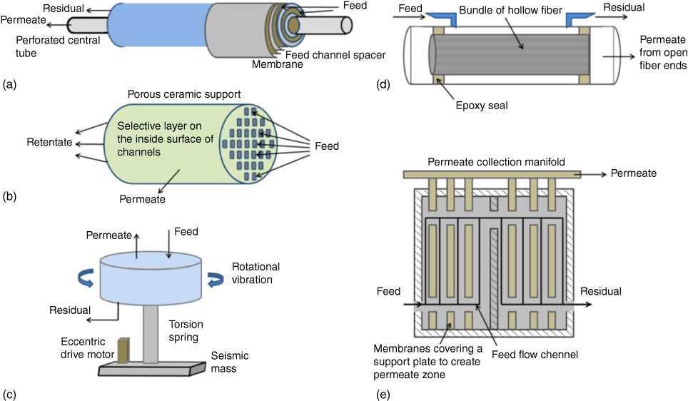
Figure 14.6 Illustrations of various membrane module configurations: (a) spiral wound, (b) monolithic ceramic, (c) vibrating disk stack, (d) hollow fiber, and (e) plate and frame [73].
When applying pervaporation for ABE separation, two types of pervaporation membranes (the organophilic and hydrophilic membranes) are used in different cases. The former is used in organic solvents recovery from fermentation broth with low concentration of solvent. In this case, the membrane will preferentially permeate organic compounds relative to water, so the organic solvents will be concentrated in permeating side. Oppositely, the latter is applied for dehydrating of solvents with low water content, in which the membrane allows water to pass through while leaving solvent in retentate. This method has significant advantages in ethanol/water azeotrope systems (at ∼4 wt% water) where traditional distillation cannot recover pure solvents without adding additional chemicals, which must be removed in the following separation step [75].
In order to improve the separation performance, the key for energy saving, a wide range of materials have been applied in the fabrication of both organophilic and hydrophilic membranes, as shown in Tables 14.4 and 14.5. Among these membranes, the polymeric membranes, PDMS and PVA membranes, are most frequently used in recovery and dehydration, respectively, due to their high selectivity, easy preparation, and low cost [116]. Besides, inorganic membranes also exhibit excellent permselective properties and high flux. However, the high preparation cost and poor mechanical properties have limited its application. In contrast, the mixed matrix membranes (MMMs), prepared by filling inorganic particles in polymeric membrane, have attracted great attention in recent years. MMMs possess high permeation flux and selectivity due to the presence of channels provided by inorganic particles while overcoming the defects existed in inorganic membranes [117–120].
Table 14.4 Pervaporation performances of different PV membranes in acetone, butanol, and alcohol recovery
| Flux (g/m2 h) | Separation factor | |||||||||
| Membrane | Concentration (wt%) | Temperature (°C) | Total | Acetone | n-Butanol | Ethanol | Acetone | n-Butanol | Ethanol | References |
| Acetone–water | ||||||||||
| Silica membrane | 5 | 30 | — | 1161.6 | — | — | 26 | — | — | [76] |
| PEBA 2533 | 5 | 23 | — | 23.2 | — | — | 3 | — | — | [77] |
| Pervap 4060 | 5 | 25 | — | 1097.7 | — | — | 58 | — | — | [78] |
| PolyAn | 5 | 25 | — | 1655.3 | — | — | 37 | — | — | [78] |
| Butanol–water | ||||||||||
| PDMS | 1 | 40 | 1282 | — | — | — | — | 42.8 | — | [79] |
| PEBA | 1 | 60 | 4196 | — | — | — | — | 21 | — | [80] |
| PTMSP | 1.5 | 70 | 1030 | — | — | — | — | 70 | — | [81] |
| PTMSP/PDMSM | 2 | 25 | 120 | — | — | — | — | 128 | — | [82] |
| Pervap 4060 | 5 | 50 | 3400 | — | — | — | — | 39 | — | [83] |
| c-PDMS/BPPO | 5 | 40 | 220 | — | — | — | — | 35 | — | [84] |
| Silicalite-1 | 2 | 70 | 110 | — | — | — | — | 150 | — | [85] |
| ZSM-5 | 5 | 30 | 223 | — | — | — | — | 47 | — | [86] |
| ZIF-8 filled PDMS | 1 | 80 | 1411 | — | — | — | — | 37 | — | [87] |
| 30% OA/POMS | 2.5 | 60 | 95.9 | — | — | — | — | 279 | — | [88] |
| Ethanol–water | ||||||||||
| MFI/mullite tube | 10 | 60 | 2550 | — | — | — | — | — | 72 | [89] |
| B-ZSM-5/monolith | 5 | 60 | 160 | — | — | — | — | — | 31 | [90] |
| MFI/silica tube | 3 | 60 | 870 | — | — | — | — | — | 69 | [91] |
| MFI/YSZ fiber | 5 | 60 | 7400 | — | — | — | — | — | 47 | [92] |
| P(VDF–HFP) | 5.1 | 40 | 2428 | — | — | — | — | — | 5.87 | [93] |
| b-Oriented silicalite-1 | 5 | 60 | 2100 | — | — | — | — | — | 85 | [94] |
Table 14.5 Pervaporation performances of different PV membranes for the dehydration of solvents
| Membrane | Organic | Water in feed (wt%) | Temperature (°C) | Flux (g/m2 h) | Separation factor | References |
| NaA | Acetone | 10 | 50 | 900 | 5 600 | [95] |
| Chitosan | Acetone | 12 | 40 | 84 | 1 276 | [96] |
| PVA | Acetone | 5 | 30 | ∼180 | 153 | [97] |
| Pervatech “PVP” silica membrane | Acetone | 10 | 70 | 2 700 | 1 800 | [98] |
| Pervap SMS | Acetone | 20 | 70 | ∼1 100 | ∼800 | [99] |
| PVA-g-AN/HEMA-Fe3O4 | Acetone | 20 | 40 | 200 | 120 | [100] |
| P84 polyimide | Acetone | 15 | 50 | 658 | 983 | [101] |
| Silica | n-Butanol | 5 | 75 | 3 000 | 250 | [102] |
| PVA/hollow fiber | n-Butanol | 5 | 80 | 800–2 600 | 500–10 000 | [103] |
| PI/PEI dual-layer | n-Butanol | 15 | 60 | 846 | 1 174 | [104] |
| QP4VP/CMCNa | n-Butanol | 10 | 60 | 2 241 | 1 100 | [105] |
| Tubular silica | n-Butanol | 5 | 70 | 4 500 | 600 | [106] |
| NaA producta | n-Butanol | 10 | 70 | 2 700 | 8 000 | [107] |
| GOPASA/mPAN | n-Butanol | 10 | 30 | 2 540 | 2 241 | [108] |
| Hyflon AD/poly(vinylidene fluoride) | n-Butanol | 13.5 | 20 | 245 | 450 | [109] |
| BPDA-ODA/DABA | Ethanol | 10 | 75 | 20 | 1 600 | [110] |
| PI2080 polyimide | Ethanol | 4 | 60 | ∼1 000 | ∼900 | [111] |
| BTDA/ODA | Ethanol | 4 | 25 | 40 | 1 300 | [112] |
| PMDA/ODA | Ethanol | 7 | 60 | 200 | 800 | [113] |
| Chitosan | Ethanol | 10 | 60 | 400 | 5 469 | [114] |
| Mitsui (A-type zeolite) | Ethanol | 10.3 | 70 | 1 120 | 18 000 | [115] |
| Silica/titanium 10% | Ethanol | 10 | 80 | 780 | 400 | [116] |
| HPC-PVA (M2) | Ethanol | 10 | 30 | 394.8 | 1 789 | [117, 118] |
a Available from Mitsui Engineering and Shipbuilding.
Current advances in in situ ABE separation from fermentation broth are shown in Table 14.6. With continuous removal of ABE solvents, the butanol toxicity is maintained at a low level, resulting in a significant improvement in productivity. Despite the various advantages in pervaporation, up to now, it still cannot entirely separate dehydrated ABE solvents from fermentation broth by one step. Another drawback of pervaporation is ABE cannot be separated from each other by pervaporation [125, 126, 129]. Therefore, distillation is needed to couple with pervaporation to purify ABE solvents. The simplified schematic diagram of the process is shown in Figure 14.7a. In the case of ethanol–water separation, the enriched ethanol–water vapors evaporate from the downstream of organophilic membrane and then enter into the dephlegmator where water is preferentially condensed and leaves as bottoms, while a further enriched ethanol vapor leaves from the top of the dephlegmator. The condensed ethanol product contains more than 95 wt% ethanol, which can be directly dehydrated [74]. Furthermore, the energy consumption of recovering biofuels through pervaporation–distillation integrated process is much more attractive. For instance, Matsumura et al. compared the two methods for n-butanol recovery (pervaporation coupled with distillation and distillation alone). It was estimated the pervaporation–distillation system only required 7.4 MJ/kg of butanol from a broth containing 0.5 wt% butanol, while the distillation needed 79.5 MJ/kg [125]. Although the integrated process shows many advantages, pervaporation with hydrophilic membranes is also necessary to reduce water content after distillation in order to get fuel ethanol due to the azeotropy in 95.6 vol.% ethanol/water mixture [130]. The integrated separation process is shown in Figure 14.7b.
Table 14.6 Current advances in in situ ABE separation from fermentation broth
| Type | Mode | Strain | Membrane | ABE in borth (g/L) | ABE in Condensate (g/L) | ABE productivity (g/L h) | ABE yield (g/g) | Total flux (g/m2 h) | Butanol separation factor | References | ||
| Butanol | ABE | Butanol | ABE | |||||||||
| Batch | Free cells | C. acetobutylicum ATCC 824 | PDMS | 6–8 | — | — | — | 0.452 | 0.169 | — | — | [121] |
| Fed-batch | Free cells | C. acetobutylicum ATCC 55 025 | Zeolite-PDMS | 6.7–8.5 | — | 169.6 | 253.3 | 0.46 | 0.32 | 61.4–97.5 | — | [122] |
| Immobilization | C. acetobutylicum XY 16 | PDMS/ceramic | 2.6 | — | 39.5 | 90 | 0.62 | 0.31 | 676 | 15.8 | [123] | |
| Immobilization | C. acetobutylicum ABE 1 201 | PDMS/PVDF | 9.5–12 | 14–19 | 180.38 | 315.31 | 0.41 | 0.38 | 170.2–276.7 | 15–28 | [124] | |
| Free cells | C. acetobutylicum ATCC 824 | PDMS | 1.8–6.6 | 3.2–10.7 | 60.4–131.6 | 85.6–202 | 0.45–0.88 | 0.13–0.35 | 561–621 | 16.1–19.8 | [125] | |
| Continuous | Free cells | C. acetobutylicum ATCC 824 | PDMS | 2.7–10.1 | 4–18 | 35.3–64 | 62.6–117.1 | 0.13–0.37 | 0.17–0.36 | 349–418 | 13.7–15.7 | [126] |
| Free cells | C. acetobutylicum CICC 8 012 | PDMS | 6–10 | — | 71–84.4 | — | 0.12–0.3 | 0.19–0.2 | 556.5–783.9 | 10 | [127] | |
| Free cells | C. beijerinckii ATCC 55 025 | PDMS/PVDF | 8.8–9.5 | — | 166.4 | 237.5 | 0.37 | 0.3 | 93.3–108.8 | 13.7 | [128] | |

Figure 14.7 Illustration of integration processes of pervaporation and distillation. (a) Pervaporation–distillation system; (b) Pervaporation for both ethanol recovery and product dehydration [73].
14.5 Distillation
Due to the severe end-product inhibition to the ABE fermentation, butanol concentration in traditional fermentation broth can hardly exceed 2.5 wt% in most cases, even though genetic and metabolic engineering methods have been used to improved the butanol tolerance of the strains [4, 20, 131, 132]. Therefore, despite the range of advantages the traditional distillation process offers, the purification processes by distillation in using ABE fermentation broth directly is considered to be the most energy-intensive and costly part of the whole bioprocess because of the low concentrations of ABE solvents in the feed [17, 18, 24]. Additionally, the fermentation broth consisting of ABE solvent as well as water offers an azeotropic mixture; thus, in most cases, a distillation process with multiple stages and an additional dehydration step is necessary in order to reach the fuel-grade butanol production [24].
To overcome the challenge of ABE solvents separation and purification, over the years, in situ recovery technologies including gas stripping, liquid–liquid extraction, adsorption, and pervaporation are recognized to be the relatively economic and feasible ways. ABE solvents concentration in these integrated processes is dramatically increased, leading to the less energy used in the solvents purification [4, 7, 18]. However, in situ recoveries of ABE productions using the technologies above can hardly achieve the commercial grade of dehydrate ABE productions. Therefore, distillation system is indispensable in vivid ABE recovery processes.
Among the different strategies in the distillation system, liquid–liquid extraction associated process was suggested to be the most achievable way in a study by van der Merwe et al. [41]. As illustrated in Figure 14.8, the ABE fermentation broth was centrifuged and the supernate was pumped into the extraction tower, the 2-ethyl-1-hexanol solvent with enriched ABE solvent was then pumped into the solvent stripper tower, and the solvent was reused in the extraction tower. After that, the overhead liquid with concentrated ABE solvent was pumped into the acetone tower and butanol tower one by one. Solvent production of acetone, ethanol, and butanol was finally collected respectively with increasement of the products boiling point. As a result, only 13 513.85 MJ/t of energy was required in the distillation system, which is only approximately 30–40% of the total utility energy requirements when compared with the traditional distillation processes feeding ABE fermentation broth directly [41]. However, since the liquid–liquid extraction always resulted in the toxicity to the ABE fermentation, it is hard to operate in a liquid–liquid extraction process unless the assistant solvent is not toxic to the culture media and under a boiling point that is far behind the ABE solvents. But even so it was suffered from the environmental influence because of the organic compounds used in the system.
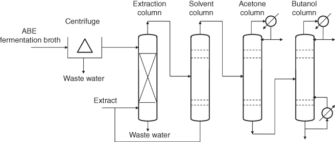
Figure 14.8 Schematic diagram of liquid–liquid extraction associated distillation system [41].
Except the solvent associated distillation processes, for butanol–water separation, taking advantages of the azeotropic phase separation and the volatility behaviors, systems with two distillation columns coupled with decanter were commonly used [24, 130]. As it was showed in Figure 14.9, the diluted butanol was first pumped into the aqueous column, and the bottom product with trace butanol was discarded. The production at the top of the column was condensed into the decanter. The water phase with approximately 8 wt% butanol was recycled, while the oil phase was pumped into the butanol column. Lower concentration of butanol at the top of the column was condensed into the decanter, while the butanol with higher concentration was collected at the bottom of butanol column. By using this system, about 99.9 wt% of butanol can be generated from binary butanol–water mixtures in Vane's study [24].

Figure 14.9 Schematic diagram of a two-column distillation decanter coupled system for butanol purification [24, 130].
As for the application of the butanol–water distillation process mentioned above, ABE solvent, the multi-constituent in the feed was studied in many researches. As it was showed in Figure 14.10, typical process of ABE distillation consisted of five columns [133]. The diluted ABE solvents were concentrated by the beer column firstly. Then, based on the boiling point of volatility compounds, acetone, ethanol, and butanol were separated in ordinal. However, because of the high energy demanded of the multistage distillation system, effort of energy optimization and process improvement has been taken into practice (Figure 14.11a). Mariano et al. [133] developed an energy-saving process with heat exchange, where 29.8 MJ/kg butanol of the specific energy was used in the butanol plant when directly feeding ABE solvents into the distillation system. Besides, Xue et al. [134] provided a modified multistage distillation system (Figure 14.11b), aiming to save energy in the beer column; a decanter was paralleled with the first stage of distillation. As a result, about 90% of total ABE solvents was collected in the organic phase and pumped into the acetone column, while more than 99% of water was removed from the bottom of the beer column.

Figure 14.10 Schematic diagram of the five stages of distillation process using ABE fermentation broth.

Figure 14.11 Schematic diagram of five stage of distillation process using ABE fermentation broth. (a) Heat exchange system [133]. (b) Decanter in paralleled with the beer column [134].
Cascaded with in situ separation techniques for ABE recovery, distillation systems above were attempted to feed the in situ-separated ABE solvents in high titer. Recovery systems of gas stripping (flash fermentation) and pervaporation have been coupled with distillation processes (Figure 14.12). Van der Merwe et al. [41] suggested a gas stripping–extraction associated process where only 9373.87 MJ/t of butanol was used. The energy requirement of the cascade separation process was far behind the processes operated with traditional distillation. As for the ABE–water system, 17 MJ/kg of butanol was the total energy requirement for butanol recovery using flash fermentation coupled with distillation was studied [8]. Besides, Van Hecke et al. [125, 126] provided a hybrid butanol purification process using pervaporation for the concentration of ABE solvents and a five-stage distillation system for ABE separation and purification. Furthermore, emphasizing the water recovery, several systems recycled the water at the bottom of water column and then reused the water in the lignocelluloses in the pretreatment processes. A dehydration membrane was used in the purification step and the butanol tower was deleted [135].

Figure 14.12 Schematic diagram of fermentation–separation–purification integrated system. (a) gas stripping–liquid extraction associated with distillation-coupled process [41]. (b) flash fermentation-multiple stage distillation coupled process [8]; (c) pervaporation-multiple stage distillation coupled process [125, 126].
14.6 Conclusion
Even though great effort of separation technologies including gas stripping, liquid–liquid extraction, adsorption, and pervaporation has been taken to overcome the limitations of low productivity and low product concentrations of ABE fermentation processes, however, up to now, there have not been any applications of these technologies in industrialization because of the less economically competitive of the processes. In order to enhance the competitiveness of ABE fermentation, an effective process with high selectivity and that is nontoxic and energy saving is encouraged. To achieve this goal, the integration of different separation technologies of the whole process is the key issue. Furthermore, given the life cycle sight, for example, the substrate cost is another limitation of the economically competitive. Thus, in order to improve the economics of ABE processes, system ideas might be more helpful.
References
- 1. Ezeji, T.C., Karcher, P.M., Qureshi, N., and Blaschek, H.P. (2005) Improving performance of a gas stripping-based recovery system to remove butanol from Clostridium beijerinckii fermentation. Bioproc. Biosyst. Eng., 27 (3), 207–214.
- 2. Lu, C.C., Jie, D., and Yang, S.T. (2013) Butanol production from wood pulping hydrolysate in an integrated fermentation-gas stripping process. Bioresour. Technol., 143, 467–475.
- 3. Qureshi, N. and Ezeji, T.C. (2008) Butanol, ‘a superior biofuel’ production from agricultural residues (renewable biomass): recent progress in technology. Biofuels Bioprod. Bioref., 2, 319–330.
- 4. Knoshaug, E.P. and Zhang, M. (2009) Butanol tolerance in a selection of microorganisms. Appl. Biochem. Biotechnol, 153, 13–20.
- 5. Jang, S.T., Malaviya, A., Cho, C., Lee, J., and Lee, S.Y. (2012) Butanol production from renewable biomass by clostridia. Bioresour. Technol., 123, 653–663.
- 6. Dürre, P. (2007) Biobutanol: an attractive biofuel. Biotechnol. J., 2, 1525–1534.
- 7. Kumar, M. and Gayen, K. (2011) Developments in biobutanol production: new insights. Appl. Energy, 88, 1999–2012.
- 8. Mariano, A.P., Keshtkar, M.J., Atala, D.I.P., Filho, F.M., Maciel, M.R.W., Filho, R.M., and Stuart, P. (2011) Energy requirements for butanol recovery using the flash fermentation technology. Energy Fuels, 25, 2347–2355.
- 9. Peralta-Yahya, P.P., Zhang, F., del Cardayre, S.B., and Keasling, J.D. (2012) Microbial engineering for the production of advanced biofuels. Nature, 488, 320–328.
- 10. Green, E.M. (2011) Fermentative production of butanol – the industrial perspective. Curr. Opin. Biotechnol., 22, 337–343.
- 11. Jin, C., Yao, M., Liu, H., Lee, C.F., and Ji, J. (2011) Progress in the production and application of n-butanol as a biofuel. Renew. Sustain. Energy Rev., 15, 4080–4106.
- 12. Li, J., Zhao, J.B., Zhao, M., Yang, Y.L., Jiang, W.H., and Yang, S. (2010) Screening and characterization of butanol-tolerant micro-organisms. Lett. Appl. Microb., 50 (4), 373–379.
- 13. Gu, Y., Jiang, Y., Wu, H., Liu, X., Li, Z., Li, J., Xiao, H., Shen, Z., Dong, H., Yang, Y., Li, Y., Jiang, W., and Yang, S. (2011) Economical challenges to microbial producers of butanol: feedstock, butanol ratio and titer. Biotechnol. J., 6 (11), 1348–1357.
- 14. Shen, C.R., Lan, E.I., Dekishima, Y., Baez, A., Cho, K.M., and Liao, J.C. (2011) Driving forces enable high-titer anaerobic 1-butanol synthesis in Escherichia coli. Appl. Environ. Microbiol., 77, 2905–2915.
- 15. Lan, E.I. and Liao, J.C. (2011) Metabolic engineering of cyanobacteria for 1-butanol production from carbon dioxide. Metab. Eng., 13 (4), 353–363.
- 16. Liu, X.B., Gu, Q.Y., and Yu, X.B. (2013) Repetitive domestication to enhance butanol tolerance and production in Clostridium acetobutylicum through artificial simulation of bio-evolution. Bioresour. Technol., 130, 638–643.
- 17. Ezeji, T.C., Qureshi, N., and Blaschek, H.P. (2004) Butanol fermentation research: upstream and downstream manipulations. Chem. Record., 4, 305–314.
- 18. Ezeji, T.C., Qureshi, N., and Blaschek, H.P. (2007) Bioproduction of butanol from biomass: from genes to bioreactors. Curr. Opin. Biotechnol., 18, 220–227.
- 19. Ni, Y. and Sun, Z. (2009) Recent progress on industrial fermentative production of acetone–butanol–ethanol by Clostridium acetobutylicum in China. Appl. Microbiol. Biotechnol., 83, 415–423.
- 20. Ezeji, T.C., Milne, C., Price, N.D., and Blaschek, H.P. (2010) Achievements and perspectives to overcome the poor solvent resistance in acetone and butanol producing microorganism. Appl. Microbiol. Biotechnol., 85, 1697–1712.
- 21. Lu, C.C., Zhao, J., Yang, S.T., and Wei, D. (2012) Fed-batch fermentation for n-butanol production from cassava bagasse hydrolysate in a fibrous bed bioreactor with continuous gas stripping. Bioresour. Technol., 104, 380–387.
- 22. Ezeji, T.C., Qureshi, N., and Blaschek, H.P. (2003) Production of acetone, butanol and ethanol by Clostridium beijerinckii BA 101 and in-situ recovery by gas stripping. World J. Microbiol. Biotechnol., 19, 595–603.
- 23. Ezeji, T.C., Qureshi, N., and Blaschek, H.P. (2004) Acetone–butanol–ethanol (ABE) production from concentrated substrate: reduction in substrate inhibition by fed-batch technique and product inhibition by gas stripping. Appl. Microbiol. Biotechnol., 63, 653–658.
- 24. Vane, L.M. (2008) Separation technologies for the recovery and dehydration of alcohols from fermentation broths. Biofuels Bioprod. Bioref., 2, 553–588.
- 25. Lee, S.Y., Park, J.H., Jang, S.H., Nielsen, L.K., Kim, J., and Jung, K.S. (2008) Fermentative butanol production by clostridia. Biotechnol. Bioeng., 101, 209–228.
- 26. Lee, J., Jang, Y.S., Choi, S.J., Im, J.A., Song, H., Cho, J.H., Seung do, Y., Papoutsakis, E.T., Bennett, G.N., and Lee, S.Y. (2012) Metabolic engineering of Clostridium acetobutylicium ATCC 824 for isopropanol–butanol–ethanol fermentation. Appl. Environ. Microbiol., 78, 1416–1423.
- 27. Xue, C., Zhao, J., Lu, C., Yang, S.T., Bai, F., and Tang, I.C. (2012) High-titer n-butanol production by Clostridium acetobutylicum JB 200 in fed-batch fermentation with intermittent gas stripping. Biotechnol. Bioeng., 109, 2746–2756.
- 28. Abdehagh, N., Tezel, F.H., and Thibault, J. (2014) Separation techniques in butanol production: challenges and developments. Biomass Bioenrg., 60, 222–246.
- 29. Mariano, A.P., Qureshi, N., Filho, R.M., and Ezeji, T.C. (2011) Bioproduction of butanol in bioreactors: new insights from simultaneous in situ butanol recovery to eliminate product toxicity. Biotechnol. Bioeng., 108, 1757–1765.
- 30. Xue, C., Zhao, J., Liu, F., Lu, C., Yang, S.T., and Bai, F.W. (2013) Two-stage in situ gas stripping for enhanced butanol fermentation and energy-saving product recovery. Bioresour. Technol., 135, 396–402.
- 31. Cai, D., Chang, Z., Gao, L., Chen, C., Niu, Y., Qin, P., Wang, Z., and Tan, T. (2015) Acetone–butanol–ethanol (ABE) fermentation integrated with simplified gas stripping using sweet sorghum bagasse as immobilized carrier. Chem. Eng. J., 277, 176–185.
- 32. Chen, Y., Ren, H., Liu, D., Zhao, T., Shi, X., Cheng, H., Zhao, N., Li, Z., Li, B., Niu, H., Zhuang, W., Xie, J., Chen, X., Wu, J., and Ying, H. (2014) Enhancement of n-butanol production by in situ butanol removal using permeating-heating-gas stripping in acetone–butanol–ethanol fermentation. Bioresour. Technol., 164, 276–284.
- 33. Ezeji, T.C., Qureshi, N., and Blaschek, H.P. (2007) Production of acetone butanol (AB) from liquefied corn starch, a commercial substrate, using Clostridium beijerinckii coupled with product recovery by gas stripping. J. Ind. Microbiol. Biotechnol., 34, 771–777.
- 34. Cai, D., Wang, Y., Chen, C., Qin, P., Miao, Q., Zhang, C., Li, P., and Tan, T. (2016) Acetone–butanol–ethanol from sweet sorghum juice by an immobilized fermentation-gas stripping integration process. Bioresour. Technol., 211, 704–710.
- 35. Oudshoorn, A., van der Wielen, L.A.M., and Straathof, A.J.J. (2009) Assessment of options for selective 1-butanol recovery from aqueous solutions. Ind. Eng. Chem. Res., 48, 7325–7336.
- 36. Qureshi, N., Hughes, S., Maddox, I.S., and Cotta, M.A. (2005) Energy-efficient recovery of butanol from model solutions and fermentation broth by adsorption. Bioprocess Biosyst. Eng., 27, 215–222.
- 37. Xue, C., Du, G.Q., Sun, J.X., Chen, L.J., Gao, S.S., Yu, M.L., Yang, S.T., and Bai, F.W. (2014) Characterization of gas stripping and its integration with acetone–butanol–ethanol fermentation for high-efficient butanol production and recovery. Biochem. Eng. J., 83, 55–61.
- 38. Maddox, I.S. (1989) The acetone–butanol–ethanol fermentation: recent progress in technology. Genet. Eng. Rev., 7, 189–200.
- 39. Barton, W.E. and Daugulis, A.J. (1992) Evaluation of solvents for extractive butanol fermentation with Clostridium acetobutylicum and the use of poly(propylene glycol) 1200. Appl. Microbiol. Biotechnol., 36, 632–639.
- 40. Groot, W.J., Soedjak, H.S., Donck, P.B., van der Lans, R.G.J.M., Luyben, K.C.A.M., and Timmer, J.M.K. (1990) Butanol recovery from fermentations by liquid–liquid extraction and membrane solvent extraction. Bioprocess Eng., 5, 203–216.
- 41. Van der Merwe, A.B., Cheng, H., Görgens, J.F., and Knoetze, J.H. (2013) Comparison of energy efficiency and economics of process designs for biobutanol production from sugarcane molasses. Fuel, 105, 451–458.
- 42. Anbarasan, P., Baer, Z.C., Sreekumar, S., Gross, E., Binder, J.B., Banch, H.W., Clark, D.S., and Toste, F.D. (2012) Integration of chemical catalysis with extractive fermentation to produce fuels. Nature, 491, 235–239.
- 43. van den Berg, C., Heeres, A.S., van der Wielen, L.A.M., and Straathof, A.J.J. (2013) Simultaneous clostridial fermentation, lipase-catalyzed esterification, and ester extraction to enrich diesel with butyl butyrate. Biotechnol. Bioeng., 110, 137–142.
- 44. Eckert, G. and Schügerl (1987) Continuous acetone–butanol production with direct product removal. Appl. Microbiol. Biotechnol., 27, 221–228.
- 45. Wayman, M. and Parekh, P. (1987) Production of acetone–butanol by extractive fermentation using dibutylohthalate as extraction. J. Ferment. Technol., 65, 295–300.
- 46. Roffler, S.R., Blance, H.W., and Wilke, C.R. (1987) In-situ recovery of butanol during fermentation, part 1: batch extractive fermentation. Bioprocess Eng., 2, 1–12.
- 47. Roffler, S.R., Blance, H.W., and Wilke, C.R. (1987) In-situ recovery of butanol during fermentation, part 2: fed-batch extractive fermentation. Bioprocess Eng., 2, 181–190.
- 48. Roffler, S.R., Blance, H.W., and Wilke, C.R. (1988) In situ extractive fermentation of acetone and butanol. Bioprocess Eng., 31, 135–143.
- 49. Qureshi, N. and Maddox, I.S. (1995) Continuous production of acetone–butanol–ethanol using immobilized cell of Clostridium acetobutylicum and integration with product removal by liquid–liquid extraction. J. Ferment. Bioeng., 80, 185–189.
- 50. Evens, P.J. and Wang, H.Y. (1988) Response of Clostridium acetobutylicum to the presence of mixed extractions. Appl. Environ. Microbiol., 54, 175–192.
- 51. Adhami, L., Griggs, B., Himebrook, P., and Taconi, K. (2009) Liquid–liquid extraction of butanol from dilute aqueous solutions using soybean-dervied biodiesel. J. Am. Oil Chem. Soc., 86 (11), 1123–1128.
- 52. Wang, Z., Lei, T., Lin, L., Yang, M., Li, Z., Xin, X., Qi, T., He, X., Shi, J., and Yan, X. (2017) Comparison of the physical and chemical properties, performance and emissions of ethyl levulinate-biodiesel-diesel and n-butanol-biodiesel-diesel blends. Energy Fuels, 31, 5055–5062.
- 53. Fadeev, A.G. and Meagher, M.M. (2001) Opportunities for ionic liquids in recovery of biofuels. Chem. Commun., 3, 295–296.
- 54. Qureshi, N. and Maddox, I.S. (2005) Reduction of butanol inhibition by perstraction: utilization of concentrated lactose/whey permeates by Clostridium acetobutylicum to enhance butanol fermentation economics. Food Bioprod. Process, 83, 42–52.
- 55. Grobben, N.G., Eggink, G., Cuperus, F.P., and Huizing, H.J. (1993) Production of acetone, butanol and ethanol (ABE) from potato wastes: fermentation with integrated membrane extraction. Appl. Microbiol. Biotechnol., 39, 494–498.
- 56. Nielsen, D.R. and Prather, K.J. (2009) In situ product recovery of n-butanol using polymeric resins. Biotechnol. Bioeng., 102 (3), 811–821.
- 57. Nielsen, D.R., Amarasiriwardena, G.S., and Prather, K.L.J. (2010) Predicting the adsorption of second generation biofuels by polymeric resins with applications for in situ product recovery (ISPR). Bioresour. Technol., 101 (8), 2762–2769.
- 58. Levario, T.J., Dai, M., Yuan, W., Vogt, B.D., and Nielsen, D.R. (2012) Rapid adsorption of alcohol biofuels by high surface area mesoporous carbons. Micropor. Mesopor. Mat., 148 (1), 107–114.
- 59. Oudshoorn, A., van der Wielen, L.A.M., and Straathof, A.J.J. (2012) Desorption of butanol from zeolite material. Biochem. Eng. J., 67, 167–172.
- 60. Águeda, V.I., Delgado, J.A., Uguina, M.A., Sotelo, J.L., and García, Á. (2013) Column dynamics of an adsorption–drying–desorption process for butanol recovery from aqueous solutions with silicalite pellets. Sep. Purif. Technol., 104, 307–321.
- 61. Abdehagh, N., Tezel, F.H., and Thibault, J. (2013) Adsorbent screening for biobutanol separation by adsorption: kinetics, isotherms and competitive effect of other compounds. Adsorption, 19 (6), 1263–1272.
- 62. Abdehagh, N., Gurnani, P., Tezel, F.H., and Thibault, J. (2015) Adsorptive separation and recovery of biobutanol from ABE model solutions. Adsorption, 21 (3), 185–194.
- 63. Ying, H., Lin, X., Chen, Y., Chen, X., Bai, J., Xiong, J., Qian, W., Xie, J., and Wu, J. (2014) Method for separating butanol. US Patent 8,766,019.
- 64. Lin, X., Li, R., Wen, Q., Wu, J., Fan, J., Jin, X., Qian, W., Liu, D., Chen, X., Chen, Y., Xie, J., Bai, J., and Ying, H. (2013) Experimental and modeling studies on the sorption breakthrough behaviors of butanol from aqueous solution in a fixed-bed of KA-I resin. Biotechnol. Bioprocess Eng., 18 (2), 223–233.
- 65. Lin, X., Wu, J., Fan, J., Qian, W., Zhou, X., Qian, C., Jin, X., Wang, L., Bai, J., and Ying, H. (2012) Adsorption of butanol from aqueous solution onto a new type of macroporous adsorption resin: studies of adsorption isotherms and kinetics simulation. J. Chem. Technol. Biotechnol., 87 (7), 924–931.
- 66. Lee, S.H., Eom, M.H., Kim, S., Kwon, M.A., Kim, J., Shin, Y.A., and Kim, K.H. (2015) Ex situ product recovery and strain engineering of Clostridium acetobutylicum for enhanced production of butanol. Process Biochem., 50 (11), 1683–1691.
- 67. Saint Remi, J.C., Baron, G., and Denayer, J. (2012) Adsorptive separations for the recovery and purification of biobutanol. Adsorption, 18 (5-6), 367–373.
- 68. Liu, X., He, L., Zheng, J., Guo, J., Bi, F., Ma, X., Zhao, K., Liu, Y., Song, R., and Tang, Z. (2015) Solar-light-driven renewable butanol separation by core–shell Ag@ ZIF-8 nanowires. Adv. Mater., 27 (21), 3273–3277.
- 69. Oudshoorn, A., van der Wielen, L.A.M., and Straathof, A.J.J. (2009) Adsorption equilibria of bio-based butanol solutions using zeolite. Biochem. Eng. J., 48 (1), 99–103.
- 70. Saravanan, V., Waijers, D.A., Ziari, M., and Noordermeer, M.A. (2010) Recovery of 1-butanol from aqueous solutions using zeolite ZSM-5 with a high Si/Al ratio; suitability of a column process for industrial applications. Biochem. Eng. J., 49 (1), 33–39.
- 71. Sharma, P. and Chung, W.J. (2011) Synthesis of MEL type zeolite with different kinds of morphology for the recovery of 1-butanol from aqueous solution. Desalination, 275 (1), 172–180.
- 72. Silvestre-Albero, A., Silvestre-Albero, J., Sepúlveda-Escribano, A., and Rodríguez-Reinoso, F. (2009) Ethanol removal using activated carbon: effect of porous structure and surface chemistry. Micropor. Mesopor. Mat., 120 (1), 62–68.
- 73. Vane, L.M. (2005) A review of pervaporation for product recovery from biomass fermentation processes. J. Chem. Technol. Biotechnol., 80 (6), 603–629.
- 74. Mortaheb, H.R., Ghaemmaghami, F., and Mokhtarani, B. (2012) A review on removal of sulfur components from gasoline by pervaporation. Chem. Eng. Res. Des., 90 (3), 409–432.
- 75. Chapman, P.D., Oliveira, T., Livingston, A.G., and Li, K. (2008) Membranes for the dehydration of solvents by pervaporation. J. Membr.Sci., 318 (1), 5–37.
- 76. Jin, T., Ma, Y., Matsuda, W., Masuda, Y., Nakajima, M., Ninomiya, K., Hiraoka, T., Fukunaga, J., Daiko, Y., and Yazawa, T. (2011) Preparation of surface-modified mesoporous silica membranes and separation mechanism of their pervaporation properties. Desalination, 280, 139–145.
- 77. Liu, F., Liu, L., and Feng, X. (2005) Separation of acetone–butanol–ethanol (ABE) from dilute aqueous solutions by pervaporation. Sep. Purif. Technol., 42, 273–282.
- 78. Rozicka, A., Niemistö, J., Keiski, R.L., and Kujawski, W. (2014) Apparent and intrinsic properties of commercial PDMS based membranes in pervaporative removal of acetone, butanol and ethanol from binary aqueous mixtures. J. Membr. Sci., 453, 108–118.
- 79. Dong, Z., Liu, G., Liu, S., Liu, Z., and Jin, W. (2014) High performance ceramic hollow fiber supported PDMS composite pervaporation membrane for bio-butanol recovery. J. Membr. Sci., 450, 38–47.
- 80. Li, Y., Shen, J., Guan, K., Liu, G., Zhou, H., and Jin, W. (2016) PEBA/ceramic hollow fiber composite membrane for high-efficiency recovery of bio-butanol via pervaporation. J. Membr. Sci., 510, 338–347.
- 81. Fadeev, A.G., Selinskaya, Y.A., Kalley, S.S., Meagher, M.M., Litvinova, E.G., Khotimsky, V.S., and Volkov, V.V. (2001) Extraction of butanol from aqueous solutions by pervaporation through poly(1-trimethylsilyl-1-propyne). J. Membr. Sci., 186, 205–217.
- 82. Borisov, I.L., Malakhov, A.O., Khotimsky, V.S., Litvinova, E.G., Finkelshtein, E.S., Ushakov, N.V., and Volkov, V.V. (2014) Novel PTMSP-based membranes containing elastomeric fillers: enhanced 1-butanol/water pervaporation selectivity and permeability. J. Membr. Sci., 466, 322–330.
- 83. Claes, S., Vandezande, P., Mullens, S., De Sitter, K., Peeters, R., and Van Bael, M.K. (2012) Preparation and benchmarking of thin film supported PTMSP-silica pervaporation membranes. J. Membr. Sci., 389, 265–271.
- 84. Liu, W., Ji, S.L., Guo, H.X., Gao, J., and Qin, Z.P. (2014) In situ cross-linked-PDMS/BPPO membrane for the recovery of butanol by pervaporation. J. Appl. Polym. Sci., 131, 6.
- 85. Shen, D., Xiao, W., Yang, J., Chu, N., Lu, J., Jin, D., and Wang, J. (2011) Synthesis of silicalite-1 membrane with two silicon source by secondary growth method and its pervaporation performance. Sep. Purif. Technol., 76 (3), 308–315.
- 86. Li, S., Tuan, V.A., Falconer, J.L., and Noble, R.D. (2003) Properties and separation performance of Ge-ZSM-5 membranes. Micropor. Mesopor. Mat., 58 (2), 137–154.
- 87. Liu, X.L., Li, Y.S., Zhu, G.Q., Ban, Y.J., Xu, L.Y., and Yang, W.S. (2011) An organophilic pervaporation membrane derived from metal–organic framework nanoparticles for efficient recovery of bio-alcohols. Angew. Chem. Int. Edit., 50 (45), 10636–10639.
- 88. Beltran, A.B., Nisola, G.M., Vivas, E.L., Cho, W., and Chung, W.J. (2013) Poly(octylmethylsiloxane)/oleyl alcohol supported liquid membrane for the pervaporative recovery of 1-butanol from aqueous and ABE model solutions. J. Ind. Eng. Chem., 19 (1), 182–189.
- 89. Lin, X., Kita, H., and Okamoto, K. (2000) A novel method for the synthesis of high performance silicalite membranes. Chem. Commun., 19, 1889–1890.
- 90. Bowen, T.C., Kalipcilar, H., Falconer, J.L., and Noble, R.D. (2003) Pervaporation of organic/water mixtures through B-ZSM-5 zeolite membranes on monolith supports. J. Membr. Sci., 215, 235–247.
- 91. Chen, H.L., Li, Y.S., Zhu, G.Q., Liu, J., and Yang, W.S. (2008) Synthesis and pervaporation performance of high-reproducibility silicalite-1 membranes. Chin. Sci. Bull., 53, 3505–3510.
- 92. Shu, X., Wang, X., Kong, Q., Gu, X., and Xu, N. (2012) High-flux MFI zeolite membrane supported on YSZ hollow fiber for separation of ethanol/water. Ind. Eng. Chem. Res., 51 (37), 12073–12080.
- 93. Chen, J., Huang, H., Zhang, L., and Zhang, H. (2014) A novel high-flux asymmetric p(VDF–HFP) membrane with a dense skin for ethanol pervaporation. RSC Adv., 4 (46), 24126–24130.
- 94. Elyassi, B., Jeon, M.Y., Tsapatsis, M., Narasimharao, K., Basahel, S.N., and Al-Thabaiti, S. (2016) Ethanol/water mixture pervaporation performance of b-oriented silicalite-1 membranes made by gel-free secondary growth. AIChE J., 62 (2), 556–563.
- 95. Okamoto, K., Kita, H., Horii, K., Tanaka, K., and Kondo, M. (2001) Zeolite NaA membrane: preparation, single-gas permeation, and pervaporation and vapor permeation of water/organic liquid mixtures. Ind. Eng. Chem. Res., 40 (1), 163–175.
- 96. Zhang, W., Li, G.W., Fang, Y.J., and Wang, X.P. (2007) Maleic anhydride surface-modification of crosslinked chitosan membrane and its pervaporation performance. J. Membr. Sci., 295 (1-2), 130–138.
- 97. Burshe, M.C., Netke, S.A., Sawant, S.B., Joshi, J.B., and Pangarkar, V.G. (1997) Pervaporative dehydration of organic solvents. Sep. Sci. Technol., 32 (8), 1335–1349.
- 98. Casado, C., Urtiaga, A., Gorri, D., and Ortiz, I. (2005) Pervaporative dehydration of organic mixtures using a commercial silica membrane: determination of kinetic parameters. Sep. Purif. Technol., 42 (1), 39–45.
- 99. Urtiaga, A.M., Casado, C., Aragoza, C., and Ortiz, I. (2003) Dehydration of industrial ketonic effluents by pervaporation. Comparative behavior of ceramic and polymeric membranes. Sep. Sci. Technol., 38 (14), 3473–3491.
- 100. Olukman, M. and Şanlı, O. (2015) A novel in situ synthesized magnetite containing acrylonitrile and 2-hydroxyethyl methacrylate grafted poly(vinyl alcohol) nanocomposite membranes for pervaporation separation of acetone/water mixtures. Chem. Eng. Process. Process Intensificat., 98, 60–70.
- 101. Mangindaan, D.W., Woon, N.M., Shi, G.M., and Chung, T.S. (2015) P84 polyimide membranes modified by a tripodal amine for enhanced pervaporation dehydration of acetone. Chem. Eng. Sci., 122, 14–23.
- 102. Petrus Cuperus, F. and van Gemert, R.W. (2002) Dehydration using ceramic silica pervaporation membranes – the influence of hydrodynamic conditions. Sep. Purif. Technol., 27 (3), 225–229.
- 103. Peters, T.A., Poeth, C.H.S., Benes, N.E., Buijs, H., Vercauteren, F.F., and Keurentjes, J.T.F. (2006) Ceramic-supported thin PVA pervaporation membranes combining high flux and high selectivity: contradicting the flux-selectivity paradigm. J. Membr. Sci., 276 (1-2), 42–50.
- 104. Wang, Y., Goh, S.H., Chung, T.S., and Na, P. (2009) Polyamide-imide/polyetherimide dual-layer hollow fiber membranes for pervaporation dehydration of C1–C4 alcohols. J. Membr. Sci., 326, 222–233.
- 105. Liu, T., An, Q.F., Zhao, Q., Lee, K.R., Zhu, B.K., Qian, J.W., and Gao, C.J. (2013) Preparation and characterization of polyelectrolyte complex membranes bearing alkyl side chains for the pervaporation dehydration of alcohols. J. Membr. Sci., 429, 181–189.
- 106. van Veen, H.M., van Delft, Y.C., Engelen, C.W.R., and Pex, P.P.A.C. (2001) Dewatering of organics by pervaporation with silica membranes. Sep. Purif. Technol., 22–23, 361–366.
- 107. Gallego-Lizon, T., Edwards, E., Lobiundo, G., and dos Santos, L.F. (2002) Dehydration of water/t-butanol mixtures by pervaporation: comparative study of commercially available polymeric, microporous silica and zeolite membranes. J. Membr. Sci., 197, 309–319.
- 108. Tsou, C.H., An, Q.F., Lo, S.C., De Guzman, M., Hung, W.S., Hu, C.C., Lee, K.R., and Lai, J.Y. (2015) Effect of microstructure of graphene oxide fabricated through different self-assembly techniques on 1-butanol dehydration. J. Membr. Sci., 477, 93–100.
- 109. Jalal, T.A., Bettahalli, N.M.S., Le, N.L., and Nunes, S.P. (2015) Hydrophobic hyflon AD/poly(vinylidene fluoride) membranes for butanol dehydration via pervaporation. Ind. Eng. Chem. Res., 54 (44), 11180–11187.
- 110. Kim, J.H., Chang, B.J., Lee, S.B., and Kim, S.Y. (2000) Incorporation effect of fluorinated side groups into polyimide membranes on their pervaporation properties. J. Membr. Sci., 169, 185–196.
- 111. Liu, R.X., Qiao, X.Y., and Chung, T.S. (2005) The development of high performance P84 co-polyimide hollow fibers for pervaporation dehydration of isopropanol. Chem. Eng. Sci., 60, 6674–6685.
- 112. Yanagishita, H., Nozoye, H., and Nakane, T. (1993) Preparation of 6FDA-based copolyimide composite membrane by CVDP process. Desalination, 90, 55–63.
- 113. Yanagashita, H., Kitamoto, D., Haraya, K., Haraya, T., Nakane, T., Tsuchiya, T., and Koura, N. (1997) Preparation and pervaporation performance of polyimide composite membrane by vapor deposition and polymerization (VDP). J. Membr.Sci., 136, 121–126.
- 114. Svang-Ariyaskul, A., Huang, R.Y.M., Douglas, P.L., Pal, R., Feng, X., Chen, P., and Liu, L. (2006) Blended chitosan and polyvinyl alcohol membranes for the pervaporation dehydration of isopropanol. J. Membr. Sci., 280, 815–823.
- 115. Sommer, S. and Melin, T. (2005) Performance evaluation of microporous inorganic membranes in the dehydration of industrial solvents. Chem. Eng. Process., 44, 1138–1156.
- 116. Sekuli, J., Luiten, M.W.J., ten Elshof, J.E., Benes, N.E., and Keizer, K. (2002) Microporous silica and doped silica membrane for alcohol dehydration by pervaporation. Desalination, 148 (1-3), 19–23.
- 117. Venkatesulu, G., Babu, P.K., Maruthi, Y., Rao, U.S.K., Subha, M.C.S., and Rao, K.C. (2015) Composite membranes comprising of hydroxypropyl cellulose-poly(vinyl alcohol) incorporated with inorganic fillers for dehydration of ethanol by pervaporation. J. Adv. Chem. Sci., 174–179.
- 118. Ciobanu, G., Carja, G., and Ciobanu, O. (2008) Structure of mixed matrix membranes made with SAPO-5 zeolite in polyurethane matrix. Micropor. Mesopor. Mat., 115 (1), 61–66.
- 119. Vankelecom, I.F.J., Depre, D., De Beukelaer, S., and Uytterhoeven, J.B. (1995) Influence of zeolites in PDMS membranes: pervaporation of water/alcohol mixtures. J. Phys. Chem., 99 (35), 13193–13197.
- 120. Widjojo, N., Chung, T.S., and Kulprathipanja, S. (2008) The fabrication of hollow fiber membranes with double-layer mixed-matrix materials for gas separation. J. Membr. Sci., 325 (1), 326–335.
- 121. Yen, H.W., Lin, S.F., and Yang, I.K. (2012) Use of poly(ether-block-amide) in pervaporation coupling with a fermentor to enhance butanol production in the cultivation of Clostridium acetobutylicum. J. Biosci. Bioeng., 113, 372–377.
- 122. Xue, C., Yang, D., Du, G., Chen, L., Ren, J., and Bai, F. (2015) Evaluation of hydrophobic micro-zeolite-mixed matrix membrane and integrated with acetone–butanol–ethanol fermentation for enhanced butanol production. Biotechnol. Biofuels, 8, 105.
- 123. Wu, H., He, A.Y., Kong, X.P., Jiang, M., Chen, X.P., Zhu, D.W., Liu, G.P., and Jin, W.Q. (2015) Acetone–butanol–ethanol production using pH control strategy and immobilized cells in an integrated fermentation–pervaporation process. Process Biochem., 50, 614–622.
- 124. Cai, D., Li, P., Chen, C., Wang, Y., Hu, S., Cui, C., Qin, P., and Tan, T. (2016) Effect of chemical pretreatments on corn stalk bagasse as immobilizing carrier of Clostridium acetobutylicum in the performance of a fermentation–pervaporation coupled system. Bioresour. Technol., 220, 68–75.
- 125. Van Hecke, W., Hofmann, T., and De Wever, H. (2013) Pervaporative recovery of ABE during continuous cultivation: enhancement of performance. Bioresour. Technol., 129, 421–429.
- 126. Van Hecke, W., Vandezande, P., Claes, S., Vangeel, S., Beckers, H., Diels, L., and De Wever, H. (2012) Integrated bioprocess for long-term continuous cultivation of Clostridium acetobutylicum coupled to pervaporation with PDMS composite membranes. Bioresour. Technol., 111, 368–377.
- 127. Chen, C., Xiao, Z., Tang, X., Cui, H., Zhang, J., Li, W., and Ying, C. (2013) Acetone–butanol–ethanol fermentation in a continuous and closed-circulating fermentation system with PDMS membrane bioreactor. Bioresour. Technol., 128, 246–251.
- 128. Xue, C., Du, G.Q., Chen, L.J., Ren, J.G., and Bai, F.W. (2014) Evaluation of asymmetric polydimethylsiloxane–polyvinylidene fluoride composite membrane and incorporated with acetone–butanol–ethanol fermentation for butanol recovery. J. Biotechnol., 188, 158–165.
- 129. Pal, R. (2008) Permeation models for mixed matrix membranes. J. Colloid. Interf. Sci., 317 (1), 191–198.
- 130. Matsumura, M., Kataoka, H., Sueki, M., and Araki, K. (1988) Energy saving effect of pervaporation using oleyl alcohol liquid membrane in butanol purification. Bioproc. Eng., 3, 93–100.
- 131. García, V., Päkkilä, J., Ojamo, H., Muurinen, E., and Keiski, R.L. (2011) Challenges in biobuanol production: how to improve the efficiency? Renew. Sustain. Energy Rev., 15, 964–980.
- 132. Liu, S. and Qureshi, N. (2009) How microbes tolerate ethanol and butanol. New Biotechnol., 26, 175–183.
- 133. Mariano, A.P., Dias, M.O.S., Junqueira, T.L., Cunha, M.P., Bonomi, A., and Filho, R.M. (2013) Butanol production in a first-generation Brazilian sugarcane biorefinery: technical aspects and economics of greenfield projects. Bioresour. Technol., 135, 316–323.
- 134. Xue, C., Zhao, X.Q., Liu, C.G., Chen, L.J., and Bai, F.W. (2013) Prespective and development of butanol as an advanced biofuel. Biotechnol. Adv., 31, 1575–1584.
- 135. Qureshi, N., Saha, B.C., Cotta, M.A., and Singh, V. (2013) An economic evaluation of biological conversion of wheat straw to butanol. Energy Convers. Manage., 65, 456–462.