
Chapter 13
Gasification Technologies for Lignocellulosic Biomass
Su J. Jeon, Soo H. Jeong, Beom J. Kim and Uen D. Lee
13.1 Introduction
As a key technology for the conversion of lignocellulosic biomass into useable renewable energy, gasification technologies have been investigated for several years. With regard to fuel quality, biomass could be classified as a low rank fuel in terms of energy density, heating value, and moisture content. Moreover, the inherent property differences of each plant species and changes in physicochemical properties due to the external environment (weather, seasonal variation, and storage) make it difficult to develop a universal energy conversion system with different feedstocks.
Together with pyrolysis and combustion, gasification is a very efficient thermochemical conversion method for solid fuels with high volatile matter like biomass. There have been various approaches used in the gasification of biomass including pretreatment of feedstock and product gas treatment. They are, however, rather young technologies, and large commercial biomass gasification plants have only recently become available. Moreover, detailed data from large plants is not open to the public at this time, making it difficult to find vital information for future studies. In this chapter, the performance of various gasification technologies for lignocellulosic biomass was investigated based on the literature survey. Analysis of relevant biomass gasification system was conducted in a quantitative manner. Therefore, in order to verify the results from small gasifiers, the results from large gasifiers were compared, even though the available data is very limited.
13.2 Gasification of Lignocellulosic Biomass
As an endothermic process, the gasification reaction requires gasifying agents, heat, and fuels that are subjected to various steps such as drying, devolatilization, reduction or gasification, and partial oxidation or controlled combustion. With single particle biomass, the sequential reaction occurs as the particle temperature increases with an adequate oxidizing agent and heat. Partial oxidation plays an important role in providing the necessary heat for the endothermic reaction. The thermal energy leads to the evaporation of moisture in the fuel particle, and various light and heavy hydrocarbons are ejected from the fuel particle through pyrolysis. At the same time, the remaining char and undegradable tar react with high temperature steam and carbon dioxide, generated from the partial oxidation process, via a heterogeneous reaction. Subsequently, additional gaseous products such as H2 and CO are also produced via heterogeneous reactions. These reactions take place simultaneously in the actual gasification process. The chemical reactions and reaction enthalpies, related to the main gasification processes, are shown in Table 13.1.
Table 13.1 Representative gasification and combustion reactions of biomass [109]
| Designation | Mechanism | ΔH (kJ/mol) |
| Oxidation | C(s) + O2⇆CO2 | −392.5 |
| C(s) + ½O2⇆CO | −110.5 | |
| Boudouard | C(s) + CO2⇆2CO | 172.0 |
| Water–gas: primary secondary | C(s) + H2O⇆CO+H2 | 131.4 |
| C(s) + 2H2O⇆CO2 + 2H2 | 90.4 | |
| Methanation | C(s) + 2H2⇆CH4 | −74.6 |
| Water–gas shift | CO + H2O⇆CO2 + H2 | −41.0 |
| Steam reforming | CH4 + H2O⇆CO + 3H2 | 205.9 |
| CH4 + 2H2O⇆CO2 + 4H2 | 164.7 | |
| CnHm + nH2O⇆nCO + (n + m/2)H2 | 210.1 | |
| CnHm + n/2H2O⇆n/2CO + (m−n)H2 + n/2CH4 | 4.2 | |
| CO2 reforming | CH4 + CO2⇆2CO + 2H2 | 247.0 |
| CnHm + nCO2⇆2nCO + m/2H2 | 292.4 | |
| CnHm + n/4CO2⇆n/2CO + (m−3n/2)H2 + (3n/4)CH4 | 45.3 | |
| H2 reforming | CO + 3H2⇆CH4 + H2O | −205.9 |
In general, the main components of product gas consist of hydrogen, carbon monoxide, carbon dioxide, methane, and some C2+ hydrocarbons along with tar, ash, H2S, COS, NH3, and so on. For the gasification system, cold gas efficiency, product gas composition and calorific value, and impurities are important parameters in performance evaluation. Furthermore, the composition and gas yield can be manipulated by changing the operating conditions or adding gas reforming or treatment processes. The product gas can be directly used as an alternative fuel to replace fossil fuels in a conventional energy system or can be transformed into high value-added chemicals or transportation fuels through various synthetic chemical processes.
13.3 Overview of Gasification Technologies of Lignocellulosic Biomass
In order to build a gasification system, along with a gasifier, a wide range of assistive technologies are necessary such as fuel handling and storage, pretreatment of feedstock, fuel feeding, product gas cleaning, ash treatment, and control of the plant. The gasification technology is, however, essential, and many physicochemical phenomena are involved, and associated technologies are so diverse that it is impossible to describe them in a single chapter. In this section, the current state of technologies will be introduced by presenting recent review papers regarding biomass gasification.
Regarding the design of gasification plants, Ruiz et al. [1] investigated gasification techniques and operation parameters. The gasifier temperature and equivalence ratio (ER) greatly affect the product gas quality, and the high moisture content of biomass and tar in the product gas represented the main technology barriers to be solved. Han and Kim [2] evaluated the literature regarding tar reduction and reported that about 40–99% tar can be reduced by physical approaches using scrubbers, cyclones, and electrostatic precipitators at the expense of tar energy. For tar reduction with self-modification, methods such as reaction temperature control (within moderate ranges), feedstock, pressure, residence time, gasifying agent, and ER were investigated, but they were not very effective. In addition, very recent technologies for gasification were reviewed by Pereira et al. [3]. They focused on the role of the technologies as novel energy systems for sustainable energy sources and greenhouse gas reduction. The effects of size, shape, structure, environment (gasifying agent), temperature, heating rate, and chemical composition of biomass on the gasification process were investigated by Kirubakaran et al. [4]. Notably, the auto-gasification of biomass into gaseous fuel by bio-oxygen, implying that the oxygen available in the biomass can be converted into CO during the gasification process, and using ash as a catalyst was reported to be feasible. For fluidized bed systems, Alauddin et al. [5] investigated various types of fluidized bed gasifiers to obtain optimum outputs such as gas composition, heating value, and tar content of the product gas, and several successful industrial plants in developed countries were introduced. For integration of the gasification system with downstream synthetic processes, Göransson et al. [6] reviewed the gasification technologies focused on the dual fluidized bed gasifiers (DFBGs) for high value-added products including transportation fuels. They reported that the reduction of tar is a crucial parameter to obtain clean syngas for automotive fuels, which can be solved by the primary method (in situ) plus secondary method (ex situ) like hot gas cleaning combined with a catalysts.
Recently, the co-gasification of coal and biomass was shown to be a very practical approach in terms of enlarging plant capacity or using limited biomass resources in a conventional coal gasifier. The co-combustion of coal and biomass has been widely applied by power plants to reduce emission of harmful gases from conventional coal power plants (i.e., NOx or SOx) while using biomass as a renewable fuel. Co-gasification has many advantages by the same reason, and many issues related to biomass supply can be solved by this approach including product gas quality control, seasonal variation of supply, and price control of feedstock. Emami-Taba et al. [7, 8] investigated the effect of fuel blending on the co-gasification of coal and biomass. They reported that the complex structure of biomass led to a higher tar production by adding more biomass to the fuel blend and less H2S and NH3 produced due to lower nitrogen and sulfur contents in biomass. In addition, E4Tech [9] reviewed various gasification technologies suitable for liquid fuel production from syngas in terms of suitable feedstocks and scales in the United Kingdom. Toward this end, they assessed the requirements of syngas-using technologies to establish which gasifier was suitable for liquid production and provided a review of current and emerging specific gasifier technologies. Finally, they compared the generic types of gasifiers. Though the report is focused on liquid fuel production with gasification, a detailed analysis was conducted, and some useful information was presented.
13.4 Classification of Gasification Technologies
Gasification systems are highly influenced by reaction conditions and parameters such as fuel characteristics, kinds of gasifying agent, reaction temperature, residence time, catalysts, and so on. Gasification technologies can be classified by the different approaches utilized to achieve the aforementioned conditions and parameters. In regard to heat supply, it can be classified as direct gasification (or autothermal) or indirect gasification (or allo-thermal). For direct gasifiers, the reaction heat is provided by the partial oxidation of the fuel in the same reactor, thereby implying fewer combustibles in the product gas because of the dilution of combustion gases from partial oxidation. In indirect gasifiers, the reaction heat is supplied from another reactor or energy source so that the heating value of the product gas is relatively higher than the direct gasifier since there is no dilution of combustion gases from partial oxidation.
On the other hand, gasification systems can be classified by gasifying agents such as air, steam, oxygen, carbon dioxide, and so on. Basically, any reactive gas can be used as the gasifying agent, but air, steam, and oxygen or mixtures of the same are the most common gasifying agents due to economic reasons and local supply. The composition and heating value of the product gas depend on the gasifying agent, and the selection of the gasifying agent is closely related to the downstream application of the product gas. Needless to say, as the most general agent, air has been used for gasification for a long time. With air-blown gasification, low heating value gas (4–7 MJ/Nm3) can be obtained because half of the product gas is nitrogen from air. It can be used in direct combustion or co-combustion in boilers, engines, or gas turbines. In steam-blown or oxygen-blown gasification, medium heating value gases (10–16 MJ/Nm3) are produced and can be used for combustion fuels as well as feedstock for further chemical synthesis processes such as valuable chemicals and alternative transportation fuels such as substitute natural gas (SNG), dimethyl ether(DME), Fischer–Tropsch (FT ) diesel, or gasoline.
Table 13.2 shows the average heating values and compositions of product gases according to the gasifying agents. The specific heating value of the steam and oxygen-blown cases are much higher than that of air-blown. In steam-blown gasification, the hydrogen, methane, and carbon dioxide contents are higher than in oxygen-blown gasification, while the carbon monoxide content is less. As shown in Table 13.2, gasification systems are highly influenced by gasifying agent, and the proper choice of target fuels, gasifying agent, gasifier design, and operating conditions is very important.
Table 13.2 Typical ranges of producer gas composition for selected gasifiers
| Gasifying agents | Air-blown (fixed bed, fluidized bed, entrained flow) | Steam-blown (fluidized bed, indirect) | Oxygen-blown (normally, entrained flow) |
| Heating value (MJ/Nm3) | 4–6 | 12–14 | 10–12 |
| H2 (vol.%) | 11–16 | 35–40 | 23–28 |
| CO (vol.%) | 13–18 | 25–30 | 45–55 |
| CO2 (vol.%) | 12–16 | 20–25 | 10–15 |
| CH4 (vol.%) | 2–6 | 9–11 | <1 |
| N2 (vol.%) | 45–60 | <1 | <5 |
Source: Bridgwater et al. 2009 [110]. Reproduced with permission of CPL Scientific Publishing Services Ltd (CPL Press).
13.5 Types of Gasification Systems
Table 13.3 shows various gasifiers with different reactor designs and operating principles. Each type of gasifier has specific requirements of reactants and operating conditions, and heat and mass transfers of the reactors are quite different because the optimum fuel size, feeding methods, relevant gasifying agent, operating temperature, and residence time are different. The distinct features yield pros and cons for specific applications, leading to different characteristics in terms of fuel availability, product gas composition, tar and dust, and optimum plant size. Even for the same type of gasifier, different setups are possible. This section will briefly describe each type of gasifier.
Table 13.3 Various types of biomass gasifier

13.5.1 Direct or Autothermal Gasifiers
In direct gasifiers, partial oxidation occurs in the gasifier, and the combustion heat and exhaust gas are directly used for the gasification reaction. Since the combustion gas is added to the product gas, the nitrogen content of the product gas is high, and the heating value is low if air is used as the gasifying agent. Compared with indirect gasifiers, direct gasifiers are relatively simple and easy to operate. The following subsections describe the characteristics of representative direct gasifiers such as auger-type, fixed bed, entrained flow, and fluidized bed gasifiers.
13.5.1.1 Auger-Type Gasifiers
In terms of reaction procedure, auger-type gasifiers are similar to fixed beds, with the Viking gasifier [10] being a widely known example. In this type of gasifier, the reaction zone can be separated using a screw. Drying and pyrolysis of biomass occurs in the screw, and the pyrolysis gas then passes through the combustion and char reduction zone. This staged reaction can significantly reduce the amount of tar in the product gas and increase the carbon conversion rate. Furthermore, the auger-type reactor and other types of reactors can be combined to assemble a type of hybrid gasifier.
13.5.1.2 Fixed (Moving) Bed Gasifiers
Fixed bed gasifiers are the simplest reactors equipped with a mechanical device to remove ash from the bottom. Fuels are stacked in the reactor, and a gasifying agent is introduced at a certain location where partial oxidation takes place. Reactions occur near the oxidation area in consecutive order: partial oxidation–gasification–pyrolysis–drying. Fixed bed systems can be classified as updraft or downdraft. By changing the fuel feeding point, oxidizer inlet, and product gas outlet, the reaction sequence can be altered to change the composition of the product gas as well as tar amount. Updraft gasifiers are simpler than downdraft gasifiers, and fuels with high moisture content can be used. The amount of tar, however, is quite high so that tar removing system of good performance is needed in the downstream. In addition, cooling is necessary for the grate because a combustion zone forms near the grate in the bottom, which can lead to heat deterioration.
In downdraft gasifiers, tar can be significantly reduced since pyrolysis gas with high tar content passes the combustion zone, which is the main benefit of this concept. The in situ tar reduction in the gasifier reduces gas cleaning burden as well as tar-related issues. In addition, grate cooling is not necessary. However, it is difficult for the product gas to get to the bottom of the reactor, and scale-up is difficult, because it is hard to control the reaction zone as compared with updraft gasifiers. Channeling phenomenon can present a further difficulty. It was reported that about 4–7% of unburned carbons are discharged with the ash. For fixed bed gasifiers, air is normally used as the gasifying agent, and product gases of low heating values are used for power generation. Table 13.4 shows the feedstock and operating details of selected fixed bed gasification systems.
Table 13.4 Feedstock and operating details of selected fixed bed gasification systems
| Feedstocks | Bed materials | Gasifying agents | ERs | Gasifier temperature (°C) | References |
| OPF (oil palm fronds) | NA | Air | 0.37 | <1000 | Atnaw et al. [31] |
| Coal | NA | Air | NA | 1100 | Zeng et al. [32] |
| Wood pellet | NA | Air | 0.29 | 800–1000 | Plis and Wilk [33] |
| Sesame wood | NA | Air | 0.21 | 1050 | Sheth and Babu [34] |
| Hazelnut shell | NA | Air | NA | 1015 | Dogru et al. [35] |
| Rubber wood | NA | Air | NA | NA | Jayah et al. [36] |
| EFB | NA | Air | 0.23–0.37 | 700–800 | Erlich and Fransson [37] |
| Wood chips | NA | Air | 0.35 | 1000–1200 | Olgun et al. [38] |
| 17 wt% HDPE + 83 wt% wood | NA | Air | 0.3–0.4 | 1092 | García-Bacaicoa et al. [39] |
| Furniture wood + charcoal | NA | Air | 0.38 | 1000 | Zainal et al. [40] |
| RDF | NA | Air | NA | NA | Beltran Tech. [17] |
| 80wt% SSk reject pellet + 20wt% wood chips | NA | Air | 0.22 | 800–1000 | Ouadi et al. [16] |
| Wood chips | NA | Air | NA | NA | Harboore [18] |
| Wood sawdust pellet | NA | Air | NA | 928 | Simone et al. [41] |
| RDF | NA | Air | 0.35 | 700–1200 | Rao et al. [42] |
| Corn straw | NA | Air | 0.32 | NA | Gai and Dong [43] |
| Red Lauan | NA | Air | NA | NA | His et al. [44] |
| Wood chips | NA | Air | 0.45 | 1100–1300 | Viking [10] |
| Straw | NA | Air + steam | NA | NA | Volund [22] |
| Wood char | NA | Air + steam | NA | 700–1050 | Van de Steene et al. [45] |
| Wood | NA | Air + steam | NA | 600–1000 | Wellman Process Engineering [22] |
| South African coal | NA | Air + steam | NA | 1034 | Pettinau et al. [46] |
| Pine sawdust | Dolomite | Steam | NA | 900 | Luo et al. [47] |
| Municipal solid waste | Nano-NiO | Steam | NA | 900 | Luo et al. [48] |
| Pig compost | NiO | Steam | NA | 800 | Wang et al. [49] |
| Pine wood charcoal | NA | Steam + O2 | NA | NA | Gujar et al. [50] |
| MSW | NA | O2 | NA | 750–1000 | Union Carbide [22] |
13.5.1.3 Entrained Flow Gasifiers
Entrained flow gasifiers were originally developed for pulverized coal (PC), and there are many commercial coal gasifiers based on this principle. This type of gasifier has the highest operating temperature, up to 2000 K, because pure oxygen is typically used as the gasifying agent and pulverized fuel is discharged near the high temperature oxy-flame. Because of the high temperature of the reactor, tar is significantly reduced, and most ashes become molten slag, and slagging discharge from the gasifier represents an important issue in the design and operation. Pulverization of solid fuel is required, and fuel feeding is another issue if operated under pressurized conditions. Two representative fuel feeding methods have been used with entrained flow gasifiers. For dry fuel, lock hopper is common (Shell gasifier and GE gasifier [11], etc.), and for wet fuels like coal slurry, the fuel is fed into the gasifier with a slurry pump (Conoco Philips [11]). This type of gasifier is useful for liquid biomass fuels like black liquor or organic waste fuel. For solid biomass, some integrated gasification combined cycle (IGCC) plants such as Buggenum [104] in the Netherlands have been used as straw for co-gasification with coal, but examples of lignocellulosic biomass are rare, since pulverization of biomass is expensive. Therefore, thermochemical pretreatments have been adopted to convert solid biomass into pyrolysis oil or torrefied fuel, and there are some examples regarding the use of pyrolysis oil and ground solid by-product (char) as feedstock for entrained flow gasifiers (Choren and KIT project [11]).
13.5.1.4 Fluidized Bed Gasifiers
Together with fixed bed gasifiers, fluidized bed gasifiers are the most relevant systems for the gasification of lignocellulosic biomass. Originally developed for coal combustion, fluidized bed technology has been widely used for thermochemical energy conversion systems of solid fuels including gasification and pyrolysis. By adding bed materials in the reactor, the heat and mass transfer of the reaction zone are significantly increased, and solid fuel and bed materials can be easily transported by hydrodynamics. Silica sand is a common bed material, and other materials like dolomite, olivine, limestone, or ilmenite have been used to reduce tar or sulfur or control product gas compositions. Compared to the fixed bed gasifiers, the temperature distribution in the reactor is uniform, and the operating temperature is less than 1000 °C in order to avoid bed agglomeration caused by ash or bed material melting. Since the bed material plays a role as a heat buffer or carrier, fuels with low heating values and high moisture contents can be used.
The direct fluidized bed gasifier can be classified as a bubbling fluidized bed (BFB) and circulating fluidized bed (CFB). In the BFB gasifier, heterogeneous reactions occur in the dense fluidized bed followed by homogenous reactions in the freeboard. The gasifier is equipped with a cyclone in order to collect entrained particles such as fly ash, unburned char, and light bed materials from attrition. The control of bubble formation and fuel particle mixing in the bed is important for the total efficiency and syngas composition. The maximum capacity of BFB gasifiers is known to be approximately a hundred tons of biomass per day under atmospheric conditions.
CFB gasifiers are composed of a riser, cyclone, downcomer, and solid recirculation valve (i.e., loop seal). In this type of gasifier, most of the bed materials circulate with the fuel particles, and the efficiency of the cyclone and solid circulation control are very important. The gasification reaction occurs in the whole loop system, and the solid volume fraction is low in most parts of the gasifier, except for in the recirculation valve. Maintenance of a balance in the solid circulation rate between the riser and the loop seal is important to ensure the smooth circulation of bed material. As compared with BFB gasifiers, a large amount of fluidization gas is necessary for CFBs, implying that the capacity of CFB gasifiers is much larger than that of BFB gasifiers. The maximum capacity of CFB gasifiers is around several hundred tons of biomass per day under atmospheric conditions. In order to meet the required residence time, the height of the reactor is much longer than that of BFB gasifiers. Both BFB and CFB gasifiers can be operated under pressurized conditions, and the capacity of the plant increases as the operating pressure increases. Tables 13.5 and 13.6 show the feedstocks and operating details of selected BFB and CFB gasification systems, respectively.
Table 13.5 Feedstock and operating details of selected bubbling fluidized bed gasification systems
| Feedstocks | Bed materials | Gasifying agents | ERs | Gasifier temperature (°C) | References |
| Wood chip | Sand | Air | 0.23 | 733 | Lim and Alimuddin [52] |
| Rice husk | Alumina sand | Air | 0.25 | 665 | Mansaray et al. [53] |
| Shelled corn | NA | Air | NA | 730 | BECON [22] |
| Rice husk | NA | Air | 0.2 | 697 | Wu et al. [54] |
| Rice husk | NA | Air | 0.24 | 828 | Behainne et al. [55] |
| Wood chips | NA | Air | NA | 650 | Energy Products of Idaho [22] |
| EFB | Silica sand | Air | 0.25 | 850 | Lahijani and Zainal [56] |
| NA | Air | 0.31 | 915 | Gregorio and Zaccariello [57] | |
| Rubber wood chip | Sand | Air | 0.38 | 750 | Kaewluan and Pipatmanomai [58] |
| Plastic waste | NA | Air | NA | 900 | E4tech (Enerkem) [9] |
| Sawdust | Sand | Air | NA | 750 | Cao et al. [59] |
| Pine sawdust | Silica sand | Air | 0.26 | 800 | Narváez et al. [60] |
| Plasmix | Olivine | Air | 0.24 | 890 | Arena et al. [61] |
| Sawdust | Calcined dolomite | Air | 0.25 | 750 | Hanping et al. [62] |
| Banagrass | Bead | Air | 0.27 | 800 | Turn et al. [63] |
| Coffee husk | NA | Air | NA | 815 | Couto et al. [64] |
| Wood chips | NA | Air | NA | 649–815 | E4tech (Alternate Gas) [9] |
| Sawdust | Silica sand | Air | 0.62 | 600 | Huang et al. [65] |
| Hazelnut shell | Silica sand | Air | 0.25 | 775 | Karatas et al. [66] |
| Wood pellet | Silica sand | Air | 0.24 | 800 | Kim et al. [67] |
| 60wt% Coal + 20wt% biomass + 20wt% plastic waste | Calcined dolomite | Air | 0.36 | 850 | Aznar et al. [68] |
| Wood pellet | Limestone | Air | NA | 850–900 | Skive [23] |
| Pine wood chip | Silica sand + dolomite | Air | 0.24 | 840 | Caballero et al. [69] |
| Olive kernels | Sand and olivine | Air | 0.2 | 750 | Skoulou et al. [70] |
| Woody waste | Silica sand, activated carbon, olivine | Air | 0.26 | 819 | Mun et al. [20] |
| Palm kernel shell | Silica bead | Air | 0.26 | 900 | Esfahani et al. [21] |
| Wood pellet | NA | Air | 0.33 | 806 | Gomez-Barea and Leckner [71] |
| Wood pellets | NA | Air + steam | NA | 850–950 | Tampella Power Inc. [22] |
| 40wt% Pine wood chip + 60wt% sabero coal | NA | Air + steam | NA | 875 | Pan et al. [72] |
| Sewage sludge | Dolomite + sand | Air + steam | 0.3 | 800 | Andrés et al. [73] |
| Wood pellet + coal | Ni-Al2O3 | Air + steam | 0.17 | 850 | Ruoppolo et al. [74] |
| Vermont wood | Ni-Al2O3 | Air + steam | NA | 650 | Carpenter et al. [75] |
| Spruce wood pellet | Ni-Al | Air + steam | 0.17 | 780 | Miccio et al. [76] |
| Pine sawdust | Sand | Air + steam | 0.23 | 800 | Lv et al. [77] |
| 60wt% Coal + 20wt%pine + 20wt% PE | Sand | Air + steam | NA | 890 | Pinto et al. [78] |
| 60wt% Coal + 40wt% bagasse | Sand | Air + steam | NA | 890 | Andre et al. [79] |
| Coal + pine sawdust | Sand | Air + steam + O2 | NA | 953 | Li et al. [80] |
| Wood pellet | NA | Air + steam + O2 | NA | 803 | Campoy et al. [81] |
| Switch grass | NA | Steam | NA | 850 | E4tech (ISU) [9] |
| Black liquor solids | NA | Steam | NA | 790–815 | E4tech (TRI) [9] |
| Biomass + coal | NA | Steam | NA | 975 | Wang et al. [82] |
| Hazelnut shell | Silica sand | Steam | NA | 775 | Karatas et al. [66] |
| Wood pellet | Silica sand | Steam | NA | 820–860 | Kim et al. [19] |
| Pine sawdust | Silica sand | Steam | NA | 750 | Herguido et al. [83] |
| Almond shell | Dolomite | Steam | NA | 770 | Rapagna et al. [84] |
| Larch wood | Calcined limestone | Steam + N2 | NA | 650 | Weerachanchai et al. [85] |
| Wood pellets | Dolomite | Steam + O2 | NA | 850 | E4tech (Carbona) [9] |
| Wood chips | Sand | O2 | NA | 900 | E4tech (EPI) [9] |
Table 13.6 Feedstock and operating details of selected circulating fluidized bed gasification systems
| Feedstocks | Bed materials | Gasifying agents | ERs | Gasifier temperature (°C) | References |
| Woody excess fraction ODW | Silica sand | Air | 0.6 | 832 | Drift et al. [86] |
| Park wood (bio-dried) | Silica sand | Air | 0.43 | 805 | Drift et al. [86] |
| Railroad ties | Silica sand | Air | 0.34 | 855 | Drift et al. [86] |
| Demolition wood + paper residue sludge | Silica sand | Air | 0.37 | 829 | Drift et al. [86] |
| Chip board materials | Silica sand | Air | 0.38 | 846 | Drift et al. [86] |
| Park wood | Silica sand | Air | 0.38 | 861 | Drift et al. [86] |
| Demolition wood | Silica sand | Air | 0.36 | 847 | Drift et al. [86] |
| Willow | Silica sand | Air | 0.37 | 827 | Drift et al. [86] |
| Herb residues | NA | Air | 0.26 | 675 | Guo et al. [87] |
| Wood chip | Silica sand | Air | 0.26 | 730 | SeenTec |
| Cypress | Silica sand | Air | 0.45 | 718 | Li et al. [88] |
| Spruce–pine–fir mix | Silica sand | Air | 0.4 | 766 | Li et al. [88] |
| SPF + cypress | Silica sand | Air | 0.35 | 730 | Li et al. [88] |
| Mixed pine bark–spruce | Silica sand | Air | 0.22 | 701 | Li et al. [88] |
| Hemlock | Silica sand | Air | 0.34 | 718 | Li et al. [88] |
| Leached orujillo | Silica sand | Air | 0.41 | 780 | García-Ibanez et al. [89] |
| Rubber wood powder | NA | Air | 0.2 | 748 | Bingyan et al. [90] |
| Rice husk | NA | Air | 0.225 | 830 | Yin et al. [91] |
| Wood | NA | Air | NA | 700–900 | Studsvik Energiteknik AB [22] |
| Demolition wood + sewage sludge | Silica sand | Air | 0.32 | 827 | Drift et al. [86] |
| Straw | Limestone + sand | Air | NA | 807 | Foster Wheeler Energia Oy [94] |
| Wood chip | Silica sand | Air | 0.39 | 800 | SeenTec |
| Sewage sludge | NA | Air | NA | 650–750 | Takahashi [92] |
| Cacao shells | Silica sand | Air | 0.34 | 822 | Drift et al. [86] |
| Wood chips | NA | Air | NA | 950–1000 | Sydkraft AB [22] |
| Wood chips | NA | Air | NA | 950–1000 | E4tech (CHRISGAS) [9] |
| Dried bark | Dolomite, limestone | Air | NA | 800 | Värö [25] |
| Wood | NA | Air | NA | 905 | E4tech (Foster Wheeler) [9] |
| Wood chips | NA | Air | NA | 915 | E4tech (Fraunhofer) [9] |
| Bark | NA | Air | NA | 800 | Lurgi Energy [22] |
| Demolition wood | Olivine | Air | 0.3 | 800 | Meijden et al. [93] |
| Woody biomass | NA | Air + steam | NA | 600–1000 | Battelle Columbus Laboratory [22] |
| Wood | Olivine | Steam | NA | 850 | Meijden et al. [93] |
| Wood chip | NA | Steam | NA | 850–900 | Bolhàr-Nordenkampf et al. [27] |
| Lignite | NA | Steam + O2 | NA | 900–950 | E4tech (Uhde) [9] |
| Sawdust | NA | Steam + O2 | NA | 950 | E5tech (CUTEC) [9] |
13.5.2 Indirect or Allo-Thermal Gasifiers
For indirect gasifiers, the necessary heat for the endothermic gasification reaction is supplied indirectly from other reactors or energy sources. In order to supply heat from the outside, heat carriers, heat exchangers, and plasma have been used. For example, a dual fluidized bed (DFB) system is composed of a gasifier and combustor, and bed materials are used as heat carriers between the two separated reactors. High temperature heat pipes have also been used for heat transfer from separated combustors to gasifiers, and heat can be provided indirectly by a plasma torch. Compared with direct gasifiers, there is no dilution of combustion gas in indirect gasifiers. Therefore, the syngas quality and heating value are very high, but the design and operation are relatively complex or expensive, and some of them are emerging technologies. The following subsections describe representative indirect gasifiers such as plasma-assisted, high temperature heat pipe and DFB gasifiers.
13.5.2.1 Plasma or Plasma-Assisted Gasifiers
Originally developed for special types of waste such as medical and military waste, this type of gasifier uses heat and ionized gas from plasma for gasification. A plasma torch powered by an electric arc is used, and a carrier gas is required as a working fluid. Nitrogen, air, and steam are normally used as the carrier gas although steam is the most suitable choice for indirect gasification [116]. A high capacity power supply is necessary, torch design is critical, and optimization of electricity use is also important. The quality of the product gas is high, and tar content is low since the high temperature plasma can break down almost all complex molecular bonds to form small molecules. In addition, inorganic materials present in the biomass become slag in the gasifier, and their treatment is also important. Therefore, slag production should be well controlled, meaning that fuel with less inorganic material is preferable. Plasma can also be used in downstream gas conditioning steps [117]. Additional useful information regarding this type of gasifier can be found in the literature [12, 115, 118, 119].
13.5.2.2 Dual fluidized Bed Gasifiers
DFB gasifiers are a kind of CFB composed of two interconnected fluidized bed reactors. One is a gasifier and the other is a combustor. Solid bed materials are used as heat carriers and they are heated in the combustor. High temperature solids are transferred to the gasifier to provide heat, and low temperature bed materials and unburned char of the gasifier are recirculated to the combustor to heat the solid by char combustion. If char is not sufficient to maintain the heat balance of the system, additional fuel can be used for combustion, and the addition of tar from the gas cleaning process to the combustor is reported to be a suitable strategy [120, 121]. Steam is generally used as the gasifying agent, and the heat of the combustion gas is used for steam generation. In DFB systems, handling of hot bed materials requires elevated levels of technology in terms of design and operation, and the balance between the gasifier and combustor is particularly important since the two reactors are highly coupled in terms of fuel and heat circulation. The amount of recirculating char and bed materials from the gasifier are the dominant input parameters for the combustor, and the heat supply to the gasifier is highly dependent on the conditions of the combustor. The gasifier and combustor can be designed as either a BFB or fast fluidized bed (FFB) reactor. Xu et al. [13] investigated the combination of BFB and FFB reactors for DFB design, and the combination of a BFB gasifier and FFB combustor was the most effective strategy for biomass gasification, which requires a longer reaction time as compared with char combustion. Details of the DFB gasifier and its application for synthetic fuel production can be found elsewhere [6]. Table 13.7 shows the feedstock and operating details of selected DFB gasification systems.
Table 13.7 Feedstock and operating details of selected dual fluidized bed gasifiers
| Feedstocks | Bed materials | Gasifying agents | Gasifier temperature (°C) | References |
| Beech wood | NA | Steam | 850 | E4tech (ECN) [9] |
| Woody biomass | NA | Steam | 800–850 | E4tech (Silva Gas & Taylor) [9] |
| Wood pellet | Silica sand | Steam | 812 | Seemann and Thunman [95] |
| Pine wood | Fe + olivine | Steam | 800 | Virginie et al. [96] |
| Coffee ground | Silica sand | Steam | 820 | Xu et al. [13] |
| Softwood pellet | Fe + olivine | Steam | 802 | Schmid et al. [97] |
| Wood chip | Calcined olivine | Steam | 850 | Rauch [98] |
| Wood pellet | Ni + olivine | Steam | 770 | Kim et al. [99] |
| Wood chips | NA | Steam | 900, 1000 | E4tech (REPOTEC) [9] |
| Wood pellet | Olivine | Steam | 800–900 | Penthor et al. [100] |
| 20wt% Coal + 80wt% wood pellet | Silica sand | Steam | 870 | Kern et al. [101] |
| Wood pellet | Olivine | Steam | 850 | Pfeifer et al. [28] |
| Wood pellet | Olivine | Steam | 800 | Göransson et al. [102] |
| Wood pellet | Silica sand | Steam | 645 | Pfeifer et al. [103] |
13.5.2.3 Heat Pipe Gasifiers
For DFB gasification systems, instead of the bed material circulation, a high temperature heat pipe can be used for heat transfer between the combustor and gasifier, which reduces heat loss and mass coupling between the two reactors. This leads to a simpler gasifier design with a much simpler operating scheme than the conventional DFB gasifiers. However, this is an emerging technology that requires further research and development to overcome obstacles ahead of commercialization. Such obstacles include very expensive, high temperature heat pipes, and the sodium, a common working fluid used in the heat pipes, is explosive if it is released into the atmosphere. Furthermore, appropriate solutions for transporting unburned char from the gasifier to the combustor need to be established. The application and technical challenges of heat pipe for indirect gasifiers were discussed previously [14].
13.5.3 Advanced Gasifiers
In addition to the aforementioned gasification systems, advanced gasification processes have been actively studied. One example is a chemical looping gasifier (CLG) [113]. It is based on chemical looping combustion (CLC) technology for the oxy-combustion of conventional fuels. In CLC systems, metal oxides are used as oxygen carriers so that an air separation unit (ASU) is not needed. In general, multiple reactors are a better option for CLG due to efficiency. The metals are oxidized by air to form metal oxides in an air reactor and are subsequently transferred to a fuel reactor where the reduction of metal oxides occurs while fuels are oxidized or gasified. In the early stages of the technology, only gaseous fuels were used in the chemical looping systems, but solid and liquid fuels can be used presently.
Another interesting system is absorption-enhanced reaction (AER) gasifiers [114]. This is similar to CLG, but calcium oxide is used as the bed material rather than metal oxides. In AER gasifiers, carbon dioxide can be captured in the gasifier using calcium oxide, and the process enhances the water–gas shift reaction shown in Table 13.1 by removing the carbon dioxide produced. This process helps to increase hydrogen content in the product gas by up to 80%. The AER process is also called the calcium looping system, and it has received attention as a useful method for hydrogen production without the use of expensive catalysts.
The other advanced system is the FLETGAS process developed by the University of Seville in Spain. This process constitutes three stages. In the first stage, the devolatilization occurs in a fluidized bed reactor, resulting in the production of reactive tar and char. In the second stage, the reactive tar is reformed with steam at a high temperature, and in the third stage, the char produced in the first stage is gasified in a moving bed downdraft reactor. Furthermore, the tar in the gas produced from the second stage is reduced through the char bed in the third stage. In the modeling study, which was compared with a one-stage fluidization bed gasification (tar concentration: 31 g/mN3 and char conversion: 59%), the concentration of tar and the char conversion efficiency in the FLETGAS process were determined to be 10 mg/mN3 and 98%, respectively [122].
So far, various kinds of gasification systems have been discussed. Among the various gasification systems, four types of gasifiers (i.e., moving/fixed bed, BFB, CFB, and DFB) are used for lignocellulosic biomass fuel in general. Table 13.8 shows the characteristics of the gasification system and the operation details. Details of the four types of gasification systems will be discussed in the following sections.
Table 13.8 Characteristics of the gasification system and operation details [111]
| Gasifiers types | Fixed beds | Fluidized beds | Entrained flow | |||
| Updraft | Downdraft | CFB | BFB | DFB | ||
| Feedstock characteristics | ||||||
| Particle size (mm) | <51 | <51 | <6 | <6 | <6 | <0.15 |
| Maximum ash tolerance (%) | 6 | 6 | 25 | 25 | 25 | 25 |
| Maximum moisture content (%) | 60 | 25 | <55 | <55 | 11–25 | <15 |
| Operational conditions | ||||||
| Oxygen demand | Low | Low | Moderate | Moderate | Low | High |
| Steam demand | High | Low | Moderate | Moderate | High | High |
| Feed-blast flow | Countercurrent | Cocurrent | — | — | — | — |
| Temperature (°C) | 800–1000 (less uniform) | 1000–1200 (less uniform) | 750–950 (more uniform) | 900–1000 (more uniform) | 800–1000 (more uniform) | 1100–1500 |
| Operating pressure | Atmospheric | Atmospheric | Atmospheric or pressurized | Atmospheric or pressurized | Atmospheric or pressurized | Atmospheric or pressurized |
| Feeding pressure (kPa) | 7–70 | 3–1050 | 7–35 | 7–35 | 7–35 | 7–350 |
| Gas velocity | Low | Low | Higher than BFB | High | Higher than BFB | High |
| θ Time | Long (15–30 min) | Long (15–30 min) | Short (5–50 s) | Short (5–50 s) | Short (5–50 s) | Very short (1–10 s) |
| Product characteristics | ||||||
| Gas output temperature (°C) | 425–650 | 425–650 | 900–1050 | 900–1050 | 800–1000 | 1250–1600 |
| LHV (MJ/Nm3) | 5–6 | 4.5–5 | 4.5–13 | 3.7–8.4 | >10 | 4–6 |
| Tar content (g/Nm3) | 30–150 | 0.015–3 | 4–20 | 3.7–61.9 | 0.2–2 | 0.01–4 |
| Plant | ||||||
| Turndown | Good | Good | Good | Good | Fair | Poor |
| Scale-up gasifier | Limited | Limited | Possible | Possible | Possible | Possible |
| Powers (MWe) | <10 | <1 | 2–100 | 1–20 | 2–50 | 5–100 |
13.6 Performance Evaluation of Biomass Gasifiers
In this section, four representative biomass gasifiers will be evaluated based on performance. The gas composition and influence of operating conditions (i.e., ER or steam to biomass ratio) on the product gas were collected based on previous reports. Notably, the kind of feedstock, gasifying agent, size of the gasifier, operating temperature and pressure, and catalyst significantly affect the final product of the gasifier, and the performance is quite different even among the same types of gasifiers. Moreover, throughout the literature, detailed information for parametric analysis is very limited for small-scale experiments, not to mention commercial plants. However, an analysis of relevant biomass gasification systems was conducted quantitatively. In order to verify the results from small gasifiers, those from large gasifiers were compared. Table 13.9 shows the representative demonstration and commercial biomass gasification plants.
Table 13.9 Representative demo and commercial biomass gasification plants
| Plants | Suppliers | Types | Scale (MWth) | Fuel types | Products | Status |
| Vilhelmina, Sweden | Bioneer | Updraft | 4–6 | Wood chip | Heat | Operation |
| Ankara, Turkey | Beltran | Updraft | 2 MWe | Wood chip | CHP | Operation |
| Harboøre, Denmark | B&W Vølund | Updraft | 4 | Wood chip | CHP | Start-up: 2000 |
| Skive, Denmark | Carbona | BFB (pressurized, 202.65 kPa) | 28 | Wood pellet | CHP | Start-up: 2007 |
| Varkaus, Finland | Foster Wheeler | BFB | 50 | Al-coated residue | Al ingots, electricity | Start-up: 2000 |
| Ruien, Belgium | Foster Wheeler | CFB | 50 | woodchip, etc. | Syngas for PC boiler | Start-up: 2002 |
| Lahti, Finland | Foster Wheeler | CFB | 45 | sawdust, forest residue, bark, SRF | Syngas for PC boiler | Start-up: 1998 |
| Varkaus, Finland | Foster Wheeler | CFB | 12 | Wood | BTL diesel (demo), syngas for lime kiln | Start-up: 2008 |
| Lahti, Finland | Valmet (Metso) | CFB | Phase 1: 45 Phase 2: 160 (250 ktpa) |
Waste wood, MSW | Phase 2: Gas boiler | Start-up: Phase 1: 1998 Phase 2: 2012 |
| Vaskiluodon Voima Oy, Finland | Valmet (Metso) | CFB | 140 | Forest residue | Co-firing | Start-up: 2012 |
| Varö, Sweden | Metso (Götaverken) | CFB | 35 | Bark, wood waste | Syngas for lime kiln | Start-up: 1987 |
| Värnamo, Sweden | Bioflow (Foster Wheeler) | CFB | 18 | Wood chip | CHP | Operation: 1993–1999 |
| Güssing, Austria | Austrian Energy & Environment | FICFB (DFB) | 8 | Wood chip | CHP | Start-up: 2001 |
| Oberwart, Austria | Austrian Energy & Environment | FICFB (DFB) | 10 | Wood chip | CHP | Start-up: 2008 |
| Götenborg, Sweden | Repotec (Phase 1) | FICFB (DFB) | 20 (gas), 80 (gas) | Wood | SNG | Phase 1 in 2012, Phase 2 in 2015 |
| Piteå, Sweden | Chemrec | Entrained | 3 | Black liquor | DME | Start-up: 2010 |
| Örnsköldsvik, Sweden | Chemrec | Entrained | 95–132 kt/yr | Black liquor | DME and methanol | Start-up due in 2013 |
| Freiberg, Germany | Choren | Entrained | 45 | Wood | BTL | Commissioning: 2010 |
13.6.1 Fixed (Moving) Bed Gasifiers
The ER, defined as the actual fed air during gasification divided by the stoichiometric air, is the most important factor in air-blown gasification. Generally, there is an optimum ER for each gasification system, and a higher ER than the optimum condition implies further oxidation reactions, which lead to the increase of carbon dioxide and decrease of combustible gases such as hydrogen, carbon monoxide, and methane.
Figure 13.1 shows the comparison of product gas composition of various fixed bed gasifiers. The results were sorted by gasifying agent and hydrogen content. The product composition is significantly affected by the gasifying agent. For oxygen-blown or steam-blown cases, the product composition is superior to air-blown cases. On the other hand, steam can be added to air-blown systems, but the addition of steam has no significant influence. In order to reform the product gas with steam, appropriate temperatures and residence times are required [15]. For most air-blown cases, the total amount of product gas, except nitrogen, is in between 40% and 50%. The Viking gasifier exhibits high hydrogen content, and the production of fuel gas is the largest due to its high carbon conversion rate arising from two-stage gasification. Notably, the main gas contents are different for each gasifier, but the deviations of the product gas in the fixed bed gasifiers are relatively small regardless of the physicochemical properties of the feedstock or operating conditions.

Figure 13.1 Comparison of dry gas composition of various fixed bed gasifiers (sorted by gasifying agent and hydrogen content).
Figure 13.2 shows the influence of ER on the H2, CO, and CH4 contents in fixed bed systems with air as the gasifying agent. The H2, CO, and CH4 contents were observed in the ranges of 7–16, 11–25, and 1–5 vol.%, respectively. As the ER increases, the H2 and CO contents increase until the ER reaches 0.3, and then the H2 and CO contents gradually decrease as the ER increases. It is well know that the average ER for autothermal gasifiers is around 0.3. If the ER is less than the optimum value, the carbon conversion rate decreases, leading to the decrease of the combustible gas. If the ER is more than the optimum value, CO2 increases due to the excessive partial oxidation. In most cases, the CH4 content decreases as the ER increases. The results reported by Ouadi et al. [16] did not show any trends because a different feedstock was used in each run in their study. According to the data collected, the optimum ER values were between 0.25 and 0.35.
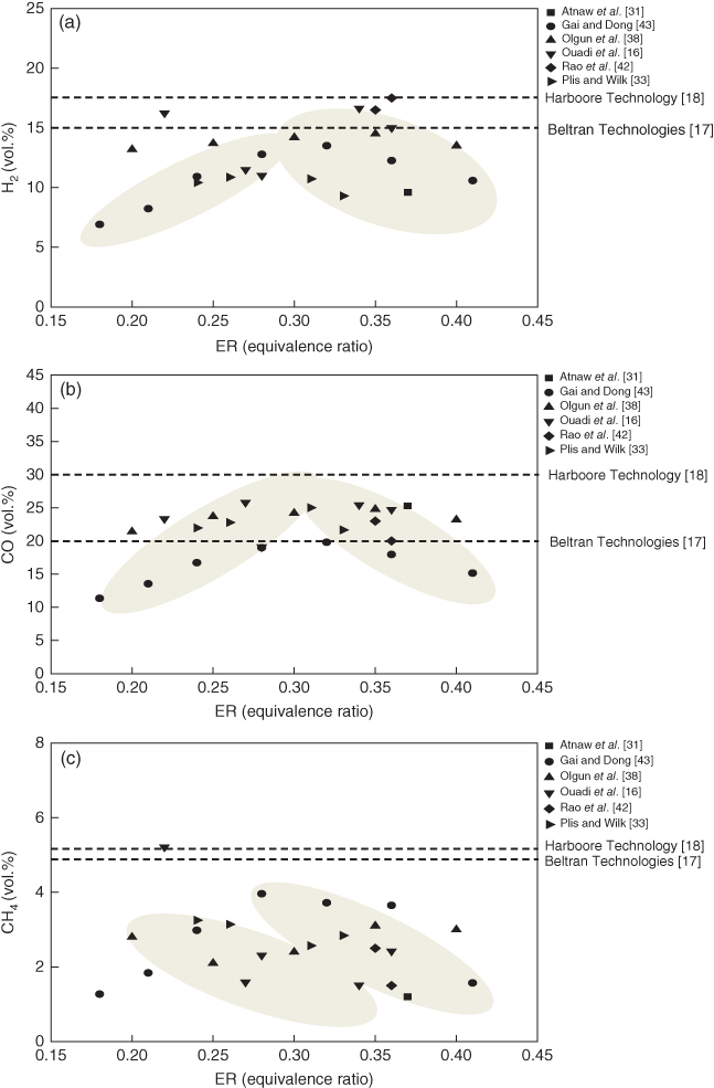
Figure 13.2 Comparison of dry gas composition in fixed bed gasification in terms of equivalence ratios: (a) Hydrogen. (b) Carbon monoxide. (c) Methane.
In Figure 13.2, the dotted line represents the product gas components obtained from commercial plants such as Beltran Technologies [17] and Harboore Technology [18]. The product gas quality from the commercial plants is better than that from small and medium-sized plants, especially for H2 and CH4. Hydrogen comes from devolatilization, char gasification, and water–gas shift reaction, and larger reactors have decided advantages in enhancing these reactions. Methane is produced from devolatilization, and it can be easily reformed under high temperature conditions (750–800 °C). Therefore, if the devolatilized gas does not pass the partial oxidation zone or if the gas residence time is short, more methane can be obtained from air-blown gasifiers. For top feeding systems, methane content can be higher since the devolatilization gas leaves the gasifier as soon as it is generated. Notably, the hydrogen and carbon monoxide trend is inversed for each gasifier. This feature can be also observed in BFBs and DFBs, and it can be clearly seen for commercial plants. As mentioned previously, this is related to char gasification and the water–gas shift reaction, which affect the production and consumption of hydrogen and carbon monoxide, respectively.
13.6.2 Bubbling Fluidized Bed (BFB) Gasifiers
Figure 13.3 shows a schematic diagram and direct photo of a BFB gasifier. In BFBs, air is supplied from the bottom, and fuel can be supplied from above the bed surface or into the bed directly. Inside the bed, char combustion and gasification occurs, and the gaseous products undergo homogeneous reactions in the freeboard. Fuel mixing and bubble control in the bed are very important for syngas composition and plant efficiency. Figure 13.4 shows the comparison of product gas composition of BFB gasifiers. The results were sorted by gasifying agent, which significantly affects the product composition. As discussed in the fixed bed cases, oxygen-blown, steam-blown, or a mixture of the two are not common for BFB systems. For steam-blown BFBs, it is not a stand-alone system since autothermal reforming is impossible with steam only. Moreover, unreacted char accumulates in the steam-blown reactor with long-term operation. Some investigations focused on steam-blown BFB gasification as a subsystem of a DFB gasifier, with an example being the work of Kim et al. [19]. ThermoChem Recovery International, Inc. (TRI) [105] is based on BFBs, but the reaction heat is provided by a pulse combustor installed inside the BFB, which can be classified as an indirect gasifier. In BFB systems, steam can be added to the air-blown system, and notably, the addition of steam significantly affects the product gas in some BFB cases, which were not in the fixed bed.

Figure 13.3 Schematic diagram of a BFB gasifier (a). Sequential reaction in the gasifier (b) (Kim et al.). Direct photo of a BFB gasifier (c, courtesy of KITECH).

Figure 13.4 Comparison of dry gas composition of various BFB gasifiers (sorted by gasifying agent and hydrogen content).
For most air-blown cases, the total amount of product gas, except nitrogen, is between 40% and 60%. The variation in the product gas composition is more diverse than that of the fixed bed cases. For example, the hydrogen content varies from 3% to 25%, and the ranges of CO, CH4, and CO2 content are wide considering differences of feedstock properties, because the product gas yield and gas composition can be significantly altered by the bed material in fluidized bed gasifiers. For example, Mun et al. [20] added activated carbon (AC) and olivine to silica sand, and the amount of product gas increased: 25.3% of H2, 21.6% of CO, 10.4% of CO2, and 4.9% of CH4. In order to reduce tar and increase gas yield, various additives have been studied including olivine, dolomite, ilmenite, AC, nickel catalysts, and so on. Most additives were studied in small-scale experiments, and additional research is necessary regarding additive use in commercial plants. If silica sand is used as the bed material, the characteristics of the product gas are similar to that of fixed bed gasifiers with the same gasifying agent.
Figure 13.5 shows the influence of ER on H2, CO, and CH4 contents in air-blown BFB gasification. The H2, CO, and CH4 contents were in the ranges of 3–33, 6–25, and 1.5–9 vol.%, respectively. Most studies have shown that the H2 and CO contents are maximized near ER = 0.25 and decrease as the ER increases because of the excessive oxidation reaction. CH4 decreases as ER increases in most studies. The optimum ER for combustible gases was between 0.25 and 0.3. The highest H2 content (about 33 vol.%) that was obtained by Esfahani et al. [21] determined the optimal hydrogen production from palm kernel shells by air gasification. The hydrogen content might be attributed to the high reactor temperature (>900 °C) and the glass bead fluidized bed material used, which included 69.3% of SiO2, 26.5% CaO, and 1.7% Fe2O3. The CaO and Fe2O3 could play a catalytic role in converting the tar (heavier hydrocarbon) into H2 and light hydrocarbons such as CH4. Corella et al. [123] conducted the air gasification of pine wood chips in a BFB reactor coupled with a catalytic reactor, and they reported that a high tar conversion rate of 98% could be achieved using a nickel-based catalyst without the deactivation of the catalyst for up to 65 h. Besides air, a steam–oxygen mixture has been used as gasifying agent. Pinto et al. [124] carried out the gasification of torrefied rice husk in a bench-scale BFB reactor, and higher H2, CO, and CH4 contents were obtained from the torrefied fuel compared with raw rice husk. Bronson et al. [125] investigated the gasification of Canadian forest residue in a pilot-scale BFB reactor and found the average combustible gas composition to be 20–22 vol.% of CO, 17–22 vol.% of H2 and 7–11 vol.% of CH4 under steam–oxygen gasification. Delgado et al. [126] conducted the steam gasification of biomass in a BFB reactor to investigate the effect of dolomite (MgO–CaO), calcite (CaO), and magnesite (MgO) on tar reduction and product gas composition and found the dolomite to be the most effective although the gas compositions in each case were similar.

Figure 13.5 Comparison of dry gas composition in BFB gasification in terms of equivalence ratios. (a) Hydrogen. (b) Carbon monoxide. (c) Methane.
In Figure 13.5, the results of alternate gas [22] and Skive plant [23] are depicted as dotted lines as a reference for commercial plants. The capacity of the former is 200 ton/day and the latter is 110 ton/day. Although the exact operating conditions were not provided for the commercial cases, the gas compositions of various studies are in between the two commercial plants, if the ER was between 0.2 and 0.3, common in autothermal BFB operations. CO content distributions of many studies are more like the results of commercial plants as compared with those of H2 and CH4. In the case of alternate gas, the H2, CO, and CH4 contents were 12.7, 15.5, and 5.7 vol.%, respectively, while for the Skive plant, the gas composition was H2: 15–16 vol.%, CO: 20 vol.%, and CH4: 4–5 vol.%. The difference between commercial plants and other plants could be attributed to operating conditions such as fuel properties, reactor temperature, bed material, ER, gasifier scale, and resultant gas analysis method. The H2 content of Skive was relatively higher than that of alternate gas because a calcium-based material, which can perform a role in the absorption of CO2 during gasification, was used as the fluidized bed material. On the other hand, the Skive plant operated in a pressurized mode of up to 200 kPa with wood pellets being used as the feedstock.
In Figure 13.5, the solid symbols represent the results of silica sand, and the open symbols represent those of catalyst addition in the bed. The graph shows the effect of catalysts on the gasification process, namely, the increase of hydrogen and methane content. Markedly, the data from the literature is diverse even under similar experimental conditions. Therefore, careful consideration is necessary to select appropriate data for a specific objective. The results of commercial plants could be a good reference for evaluating the results from small-scale experiments. In other words, experiments should be designed in a practical point of view. For small-scale experimental setup, electrical heaters have been widely used but can mislead the experiment if the boundary conditions are unrealistic for certain cases. For example, for ERs less than 0.2, gasification reactions cannot be maintained in the autothermal mode without the addition of external heat.
13.6.3 Circulating Fluidized Bed (CFB) Gasifier
Figure 13.6 shows a schematic diagram and direct photo of a CFB gasifier. It is based on a FFB system that circulates most of the particles in the reactor with the momentum of the fluidizing gas. Therefore, CFB gasifiers are composed of a riser, cyclone, and solid recirculation valve, and comparing with the similar size of BFBs, much more gas is supplied to the reactor for particle circulation, and the capacity of CFB gasifiers is much larger than that of BFB gasifiers. Unlike BFBs, all necessary reactions occur at the same time in the whole CFB system, and this can lead to different product gas compositions for the same kinds of fuel and gasifying agent. Figure 13.7 shows the comparison of product gas composition of CFB gasifiers. The results were sorted by a gasifying agent, which significantly affects the product composition. As aforementioned, oxygen-blown, steam-blown, or a mixture of the two are special cases, and air-blown is the most relevant for CFB gasifiers.
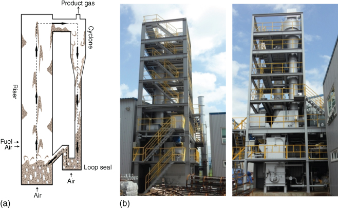
Figure 13.6 Schematic diagram of a CFB gasifier (a). Direct photo of a CFB gasifier (b, courtesy of Hasol Seentec co. Ltd).
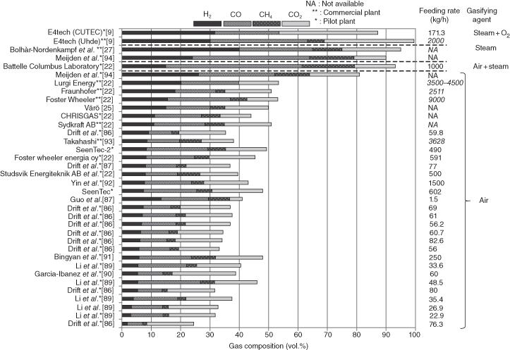
Figure 13.7 Comparison of dry gas composition of various CFB gasifiers (sorted by gasifying agent and hydrogen content).
The plant sizes of CFB gasifiers are much larger than those of fixed bed or BFB cases. For air-blown CFB gasifiers, the total amount of product gas except nitrogen is between 30% and 50%, and the variation in the product gas composition is less than that of the fixed bed or BFB cases. In most air-blown cases, the amount of combustible gases tends to increase as the plant size increases. Note that the total combustibles in the product gas of average CFB gasifiers are less than the other types of gasifiers. For example, hydrogen contents of most CFB gasifiers are less than 10%, and this is because partial oxidation occurs at the same location of gasification and pyrolysis reaction in a CFB system. During the partial oxidation, the product gas can be combusted, and raw biomass leads to less hydrogen, which is easy to burn. For fixed bed and BFB cases, the reduction zone is separated from the partial oxidation zone, and the combustibles can avoid oxidation process until leaving the gasifier. In addition, most CFB gasifiers use silica sand as a bed material, which has no catalytic effects. This is because most CFBs are larger than BFBs, which means that it is commercially difficult to use expensive catalytic bed materials in CFBs. Recent investigations have focused on the use of catalytic bed materials in CFBs [24].
Figure 13.8 shows the influence of ER on H2, CO, and CH4 contents of air-blown CFB gasification. The H2, CO, and CH4 contents were in the ranges of 3–17, 5–22, and 1.5–9.5 vol.%, respectively. Most studies have shown that the H2 and CO contents become maximized near ER = 0.25 and thereafter decrease as ER increases. Except for the result of Bingyan et al. [90], the combustibles decrease as ER increases. In Figure 13.8, the results of Foster Wheeler [9], Värö [25], and Värnamo [26] are depicted as dotted lines as a reference of commercial or pilot plants. Note that the results from large plants are better than those of small plants. This can be explained by the fuel residence time of most small CFB systems, which is not enough for perfect carbon conversion. The larger plants are advantageous in having longer residence times compared with the small plants. However the height should not be scaled from pilot to demonstration scale.

Figure 13.8 Comparison of dry gas composition in CFB gasification in terms of equivalence ratios. (a) Hydrogen. (b) Carbon monoxide. (c) Methane.
13.6.4 Dual Fluidized Bed (DFB) Gasifiers
Figure 13.9 shows a schematic diagram and direct photo of the pilot-scale DFB gasifiers. The DFB of this figure is the combination of a BFB gasifier and FFB combustor. This configuration is one of the representative options of DFB that was adopted in many commercial plants such as Güssing [27], Oberwart [106], and Götenborg [107] in Austria. As alternative options, the combination of a FFB gasifier and FFB combustor or the combination of a FFB gasifier and BFB combustor is possible, and the Silva gas system and ECN gasifier [9] are the representative examples, respectively. Figure 13.10 shows the concept of a DFB gasification system. As shown in Figure 13.10, solid bed materials are circulating in the interconnected fluidized beds as heat carriers, and they transfer heat from the combustor to the gasifier. The unburned char of the gasifier is used as a fuel for combustion, and additional fuel can be provided into the combustor if necessary. In general, superheated steam was used as a gasifying agent as well as a fluidization gas in the gasifier. Air is used as an oxidizer in the combustor, and heat of the combustion gas is used for steam generation. In order to avoid mixing of product gas from combustion gas, loop seals have been used between the two reactors.

Figure 13.9 Schematic diagram of DFB gasifier (a). Direct photo of a DFB gasifier (b, courtesy of KITECH).
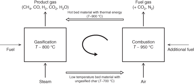
Figure 13.10 Concept diagram of DFB gasifier.
Figure 13.11 shows the comparison of product gas composition of various DFB gasifiers. For all cases, the gasifying agent is steam, most of the product gas is combustible, and inert gas in the product gas is significantly less than the other gasifier types. The inert gases like nitrogen come from bypassing of combustion gas or entrainment during fuel feeding. The syngas from DFB has been used as a feedstock of catalytic synthesis process as well as power generation. Note that the hydrogen content of DFB is very high, ranging from 20% to 70%, which is mainly contributed by steam–char gasification and water–gas shift reaction (Table 13.1). In the configuration of a BFB gasifier and FFB combustor, the hydrogen content can be obtained up to 40%, and with specific bed materials, it can be increased more. For the case of Pfeifer et al. [28], the AER process was used, and the hydrogen content was increased up to 72%. High hydrogen content is preferred for chemical synthesis such as FT synthesis and SNG synthesis that need H2/CO = 2 or 3, respectively.

Figure 13.11 Comparison of dry gas composition of various DFB gasifiers (sorted by gasifying agent and hydrogen content).
Figure 13.12 shows the influence of steam to biomass ratio (S/B) on H2, CO, and CH4 contents of steam-blown DFB gasification. As shown in the figure, the gas composition is dependent on S/B, and above a certain range of steam (i.e., S/B = 1.4), the increase of steam has no effect on the product gas composition. In general, the conversion efficiency of steam is relatively lower than the other gasifying agents, and it was known that only 10–15% of steam is converted into product gas [28]. As mentioned before, nitrogen content in the product gas is less than 5%, and H2, CO, and CH4 contents were in the ranges of 10–60, 15–40, and 7–17%, respectively. The hydrogen content is very sensitive S/B ratio, and its mole fraction is directly proportional to S/B. The mole fraction of carbon monoxide is inversely proportional to S/B, and methane content has weak correlation with S/B. In Figure 13.12, the results of Repotec and Silva Gas & Taylor [9] are depicted as dotted lines as a reference of commercial plants. Both plants have the same type of combustor, but the configuration of gasifier is different. The former is the combination of BFB gasifier and FFB combustor, while the latter is FFB gasifier and FFB combustor. Note that the two gasifiers have very different gas composition because of the gasifier configurations.
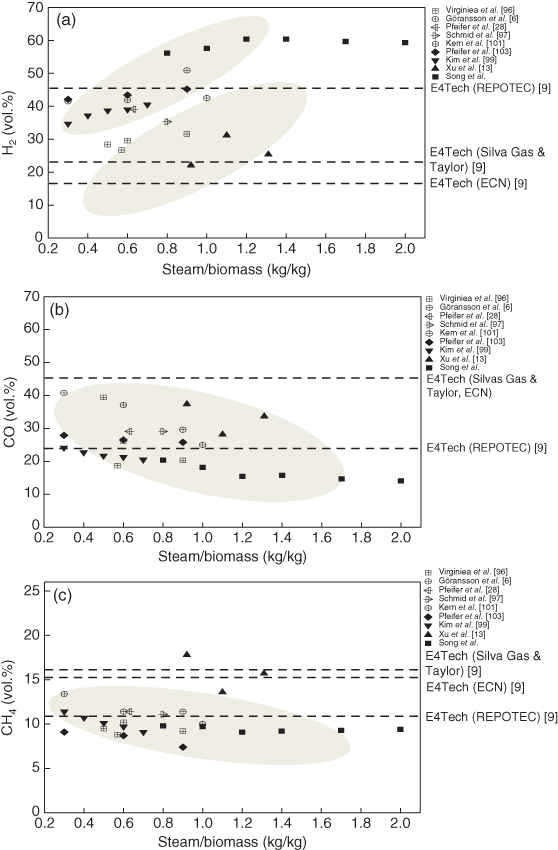
Figure 13.12 Comparison of dry gas composition in DFB gasification in terms of equivalence ratios: (a) Hydrogen. (b) Carbon monoxide. (c) Methane.
In Repotec case, hydrogen content is much higher than the other case because BFB gasifier provides enough time for char–steam gasification and homogeneous reactions for enhancing hydrogen production: water–gas shift reaction and steam methane reforming (Table 13.1). The carbon monoxide and methane contents decrease due to the aforementioned reactions. In Silva Gas & Taylor case, the hydrogen content is low, and carbon monoxide and methane contents are high because the residence time of FFB gasifier is short, which leads to less char–steam gasification and steam reforming reactions. Therefore, hydrogen yield is less than the other case, and the carbon monoxide and methane contents are high. Note that most results from small plants are between the results of two commercial plants when S/B is less than one, which is a common gasification condition. In Figure 13.12, the result of ECN pilot plant was also depicted. The ECN DFB gasifier is a combination of FFB gasifier and BFB combustor. As shown in Figure 13.12, the results are very similar to those of Silva Gas & Taylor case because the gasifier is the same type of Silva Gas & Taylor. In the ECN DFB gasifier, the FFB gasifier is inside the BFB combustor where it is expected to receive heat transferred from the combustor to gasifier wall boundaries. Note that configuration of the gasifier is more dominant than that of the combustor in DFB systems. In addition to the product gas composition, different combinations of BFB and FFB for gasifier or combustor affect the performances of the DFB gasifiers such as operating characteristics, syngas yield, tar generation, and scale-up characteristics. Therefore, appropriate design selection is necessary for DFB systems considering gas cleaning process and end use of the product gas.
13.7 Industrial Biomass Gasification Plants
All over the world, especially in developed countries such as the EU, North America, and Japan, biomass gasification and its technologies have been widely studied, and many biomass gasification plants have been commercialized. In North America, there are many fixed bed gasifier manufacturers that have experience with commercial technologies such as Nexterra [29], Plasco [30], Beltran [17], and Community Power [11]. In fluidized bed systems, the gasification of black liquor was developed by TRI [105], and a Silva gas system [9] represented by a DFB system was successfully operated in a commercial plant at 200 ton/day. America secured cheap natural gas through commercial shale gas in recent years. Nevertheless, the development of renewable energy including biomass is in progress to achieve energy independency. For example, ethanol production from lignocellulosic biomass has gained renewed interest to reduce the consumption of corn-based biomass and to meet the demands of the rapidly growing ethanol market.
In the EU, many fluidized bed gasification systems have been commercialized, and the size of the plant is increasing. For BFBs, the Skive gasifier [23] is a representative example. The nominal thermal output is 19.5 MWth (maximum capacity: 28 MWth) under the system pressure of 0.5–2 bar. Wood pellets are used as the feedstock, and the plant produces 6 MWe of electric power and 11.5 MWth of heat in the CHP mode. In addition, the product gas can be burned in gas boilers, and the biomass to electric power efficiency is 31%, while the overall efficiency is up to 90%. In CFBs, the Varö gasifier [25] in Sweden and Lahti gasifier [112] in Finland have been successfully operated. The former has been used for supplying product gas into rotary kiln for cement production. The feedstock is dried wood bark from nearby pulp mills, and the thermal capacity is 35 MWth. Since the product gas is supplied to the combustor of the kiln, gas cleaning is not necessary. The Lahti gasifier is another example of using gasification technology with a conventional energy system. In the first phase, which began in 1998, the thermal capacity was over 45 MWth, and the product gas was used for the co-combustion of coal in a PC boiler of 360 MWth. This process replaces 15% of coal, and the SOx, NOx, and CO2 emissions of the PC boiler were reduced by employing reburning technology with syngas from the gasifier. In the second phase, which was initiated in 2012, the entire system was repowered to use municipal waste together with biomass. Moreover, the capacity of the gasifier was increased up to 160 MWth (2 × 80 MWth), which is equivalent to 250 000 ton/a solid recovered fuel (SRF) gasification. The product gas is currently burned in a gas boiler to produce 50 MWe of electricity and 90 MWth of district heating. In order to prevent high temperature corrosion with alkali chloride from municipal solid waste (MSW), a hot gas cleaning process was introduced in between the gasifier and boiler. Also, a new line was built in 2012. The CFB gasifier in Vaskiluodon Voima Oy in Finland is the world's largest biomass gasification plant with a capacity of 140 MWth, and the gasifier is connected to an existing 560 MW power plant for topping the product gas to a coal-fired boiler [127]. The Värnamo gasifier [26] in Sweden is another interesting CFB gasification system. It is a pressurized fluidized bed gasifier, and the syngas was used as fuel for a gas turbine. After successful operation with the gas turbine, the plant was redesigned into a synthetic liquid fuel production system integrated with biomass gasification under the name of CHRIS project. The project, however, was discontinued several years ago.
Recently, indirect gasification systems with DFB technologies have been introduced in the market. The Güssing gasifier [27] in Austria is representative of DFB gasifiers that have been successfully operated since 2001. The original technology was developed at the Technical University of Wien (TU Wien), and the gasifier has been used for many research projects as well as for commercial purposes. The Oberwart gasifier [106] is a 10 MWth commercial gasifier of the same design as the Güssing, which uses wood chips as feedstock. Recently, the size of DFB gasifiers has increased, and the Götenborg SNG plant [107], which includes a DFB biomass gasifier using the Austrian DFB gasification technology, has been fully operational since 2014. For the first phase, a 32 MWth gasification plant has been operated for a 20 MWth SNG synthesis process, and an 80 MW SNG plant is planned for phase 2 [51].
As an industrial entrained flow gasifier for biomass, the Choren gasifier [108] in Germany is the largest. This 45 MWth plant was designed to supply bio-syngas for FT synthesis of liquid fuel. In order to meet the requirements of entrained flow gasification systems, pyrolysis oil and ground char were used as the feedstock. Unfortunately, the project was discontinued because of many obstacles. As discussed previously, various gasifiers have been developed on the industrial scale, and plant size is growing steadily. Some projects were successful, while others were not. In commercial projects, the economic feasibility of the plant is very important, in addition to technological obstacles. The market for renewable energy is so volatile that many external environments can affect the project management such as feedstock price, governmental subsidies, and price of conventional fossil fuels.
13.8 Conclusion
The objective of this paper was to evaluate the performance of various technologies used for the gasification of lignocellulosic biomass. The investigation is based on a literature survey that provides detailed information for quantitative comparison. The analysis focused on fixed bed and fluidized bed gasifiers, which are the most relevant gasification systems for lignocellulosic biomass. Notably, the quality of the product gas was significantly affected by fuel properties, gasifying agents, gasifier size, and operating conditions, even if the same type of gasifier was used. Considerable differences were observed between the results from commercial plants and those from small plants, with the extent of these differences being even higher for the fixed bed and CFB gasifiers. These results imply that detailed verifications of experimental conditions and careful interpretations of results are necessary for small-scale gasifiers, especially for fixed bed and CFB gasifiers. Regarding the comparison between gas compositions of commercial and research plants, the larger differences were observed in the hydrogen and methane contents, while the difference in carbon monoxide content was relatively small. These results might be attributed to the residence time difference caused by the size of the reactor. Overall, these results could be used as a platform on which to design and model future experiments as well as an appropriate selection guide for gasification technologies targeted for specific fuels and applications.
References
- 1. Ruiz, J.A., Juárez, M.C., Morales, M.P., Muñoz, P. et al. (2013) Biomass gasification for electricity generation: review of current technology barriers. Renew. Sustainable Energy Rev., 18, 174–183.
- 2. Han, J. and Kim, H.J. (2008) The reduction and control technology of tar during biomass gasification/pyrolysis: an overview. Renew. Sustainable Energy Rev., 12 (2), 397–416.
- 3. Pereira, E.G., Silva, J.N.D., Oliveira, J.L.D., and Machado, C.S. (2012) Sustainable energy: a review of gasification technologies. Renew. Sustainable Energy Rev., 16, 4753–4762.
- 4. Kirubakaran, V., Sivaramakrishnan, V., Nalini, R., Sekar, T. et al. (2009) A review on gasification of biomass. Renew. Sustainable Energy Rev., 13, 179–186.
- 5. Alauddin, Z.A.B.Z., Lahijani, P., Mohammadi, M., and Mohammadi, A.R. (2010) Gasification of lignocellulosic biomass in fluidized beds for renewable energy development: a review. Renew. Sustainable Energy Rev., 14, 2852–2862.
- 6. Göransson, K., Söderlind, U., He, J., and Zhang, W. (2011) Review of syngas production via biomass DFBGs. Renew. Sustainable Energy Rev., 15, 482–492.
- 7. Emami-Taba, L., Irfan, M.F., Daud, W.M.A.W., and Chakrabarti, M.H. (2013) Fuel blending effects on the co-gasification of coal and biomass – a review. Biomass Bioenergy, 57, 249–263.
- 8. Emami-Taba, L., Irfan, M.F., Daud, W.A.M.W., and Chakrabarti, M.H. (2012) The effect of temperature on various parameters in coal, biomass and CO-gasification: a review. Renew. Sustainable Energy Rev., 16, 5584–5596.
- 9. E4tech (2009) Review of Technologies for Gasification of Biomass and Waste. Final report.
- 10. Ahrenfeldt, J. (2007) Characterization of biomass producer gas as fuel for stationary gas engines in combined heat and power production. Ph.D. thesis. Technical University of Denmark.
- 11. Rezaiyan, J. and Cheremisinoff, P.N. (2005) in Gasification Technologies: A primer for Engineers and Scientist (ed. H. Heinemann), Taylor & Francis, Califonia.
- 12. Hlina, M., Hrabovsky, M., Kavka, T., and Korand, M. (2014) Production of high quality syngas from argon/water plasma gasification of biomass and waste. Waste Manag., 34, 63–66.
- 13. Xu, G., Murakami, T., Suda, T., Matsuzaw, Y. et al. (2009) Two-stage dual fluidized bed gasification: its conception and application to biomass. Fuel Process. Technol., 90, 137–144.
- 14. Karl, J. (2014) Biomass heat pipe reformer-design and performance of an indirectly heated steam gasifier. Biomass Convers.Biorefin., 4 (1), 1–14.
- 15. Sharma, A.M., Kumar, A., and Huhnke, R.L. (2014) Effect of steam injector location on syngas obtained from air-steam gasifier. Fuel, 116, 388–394.
- 16. Ouadi, M., Brammer, J.G., Kay, M., and Hornung, A. (2013) Fixed bed downdraft gasification of paper industry wastes. Appl. Energy, 103, 692–699.
- 17. http://www.Beltran.co.kr (accessed 06 July 2016).
- 18. Heeb R. (2010) Updraft Gasification: A Status on the Harboore Technology. IEC Gasification Conference Publication. Babcock & Wilcox Vølund A/S, Esbjerg, Dänemark.
- 19. Kim, K.S., Kim, Y.D., Yang, C.W., Moon, J.H. et al. (2013) Long-term operation of biomass-to-liquid systems coupled to gasification and Fischer–Tropsch processes for biofuel production. Bioresour. Technol., 127, 391–399.
- 20. Mun, T.Y., Kim, J.O., Kim, J.W., and Kim, J.S. (2011) Influence of operation conditions and additives on the development of producer gas and tar reduction in air gasification of construction woody wastes using a two-stage gasifier. Bioresour. Technol., 102, 7196–7203.
- 21. Esfahani, R.M., Ghani, W.A.W.A.K., Salleh, M.A.M., and Ali, S. (2012) Hydrogen-rich gas production from palm kernel shell by applying air gasification in fluidized bed reactor. Energy Fuel, 26, 1185–1191.
- 22. https://www.netl.doe.gov/File%20Library/Research/Coal/energy%20systems/gasification/pubs/BMassGasFinal.pdf (accessed 19 July 2016).
- 23. https://www.ecn.nl/fileadmin/ecn/units/bio/Biomassa/Syngas_and_SNG/Gasification_2010/Biomass_gasification_plant_in_Skive.pdf (accessed 19 July 2016).
- 24. Devi, L., Craje, M., Thüne, P., and Ptasinski, K.J. (2005) Olivine as tar removal catalyst for biomass gasifiers: catalyst characterization. Appl. Catal. A Gen., 294 (1), 68–79.
- 25. http://www.processeng.biz/iea-fbc.org (accessed 06 July 2016).
- 26. Ståhl, K. and Neergaard, M. (1998) IGCC power plant for biomass utilization, Värnamo, Sweden. Biomass Bioenergy, 15 (3), 205–211.
- 27. Bolhàr-Nordenkampf, M., Rauch, R., Bosch, K., Aichernig, C. et al. (eds) (2003) Biomass CHP Plant Güssing-Using Gasification for Power Generation. Proceeding of the 2nd Regional Conference on Energy Technology Towards a Clean Environment, February 12–14, 2003, Phuket, Thailand.
- 28. Pfeifer, C., Puchner, B., and Hofbauer, H. (2009) Comparison of dual fluidized bed steam gasification of biomass with and without selective transport of CO2. Chem. Eng. Sci., 64 (23), 5073–5083.
- 29. http://www.nexterra.ca (accessed 06 July 2016).
- 30. http://www.plascoenergygroup.com (accessed 06 July 2016).
- 31. Atnaw, S.M., Sulaiman, S.A., and Yusup, S. (2013) Syngas production from downdraft gasification of oil palm fronds. Energy, 61, 491–501.
- 32. Zeng, X., Wang, F., Li, H., Wang, Y. et al. (2014) Pilot verification of a low-tar two-stage coal gasification process with a fluidized bed pyrolyzer and fixed bed gasifier. Appl. Energy, 115, 9–16.
- 33. Plis, P. and Wilk, R.K. (2011) Theoretical and experimental investigation of biomass gasification process in a fixed bed gasifier. Energy, 36, 3838–3845.
- 34. Sheth, P.N. and Babu, B.V. (2009) Experimental studies on producer gas generation from wood waste in a downdraft biomass gasifier. Bioresour. Technol., 100 (12), 3127–3133.
- 35. Dogru, M., Howarth, C.R., Akay, G., Keskinler, B. et al. (2002) Gasification of hazelnut shells in a downdraft gasifier. Energy, 27 (5), 415–427.
- 36. Jayah, T.H., Aye, L., Fuller, R.J., and Stewart, D.F. (2003) Computer simulation of a downdraft wood gasifier for tea drying. Biomass Bioenergy, 25 (4), 459–469.
- 37. Erlich, C. and Fransson, T.H. (2011) Downdraft gasification of pellets made of wood, Palm-oil residues respective bagasse: experimental study. Appl. Energy, 88 (3), 899–908.
- 38. Olgun, H., Ozdogan, S., and Yinesor, G. (2011) Results with a bench scale downdraft biomass gasifier for agricultural and forestry residues. Biomass Bioenergy, 35 (1), 572–580.
- 39. García-Bacaicoa, P., Mastral, J.F., Ceamanos, J., Berrueco, C. et al. (2008) Gasification of biomass/high density polyethylene mixtures in a downdraft gasifier. Bioresour. Technol., 99, 5485–5491.
- 40. Zainal, Z.A., Rifau, A., Quadir, G.A., and Seetharamu, K.N. (2002) Experimental investigation of a downdraft biomass gasifier. Biomass Bioenergy, 23 (4), 283–289.
- 41. Simone, M., Barontini, F., Nicolella, C., and Tognotti, L. (2012) Gasification of pelletized biomass in pilot scale downdraft gasifier. Bioresour. Technol., 116, 403–412.
- 42. Rao, M.S., Singh, S.P., Sodha, M.S., Dubey, A.K. et al. (2004) Stoichiometric, mass, energy and exergy balance analysis of countercurrent fixed-bed gasification of post-consumer residues. Biomass Bioenergy, 27, 155–171.
- 43. Gai, C. and Dong, Y. (2012) Experimental study on non-woody biomass gasification in a downdraft gasifier. Int. J. Hydrogen Energy, 37 (6), 4935–4944.
- 44. His, C.L., Wang, T.Y., Tsai, C.H., Chang, C.Y. et al. (2008) Characteristics of an air-blown fixed-bed downdraft biomass gasifier. Energy Fuels, 22 (6), 4196–4205.
- 45. Van de Steene, L., Tagutchou, J.P., Mermoud, F., Martin, E. et al. (2010) A new experimental continuous fixed bed reactor to characterize wood char gasification. Fuel, 89 (11), 3320–3329.
- 46. Pettinau, A., Frau, C., and Ferrara, F. (2011) Performance assessment of a fixed-bed gasification pilot plant for combined power generation and hydrogen production. Fuel Process. Technol., 92 (10), 1946–1953.
- 47. Luo, S., Zhou, Y., and Yi, C. (2012) Syngas production by catalytic steam gasification of municipal solid waste in fixed bed reactor. Energy, 44 (1), 391–395.
- 48. Luo, S., Xiao, B., Hu, Z., Liu, S. et al. (2009) Hydrogen-rich gas from catalytic steam gasification of biomass in a fixed bed reactor: Influence of temperature and steam on gasification performance. Int. J. Hydrogen Energy, 34 (5), 2191–2194.
- 49. Wang, J., Xiao, B., Liu, S., Hu, Z. et al. (2013) Catalytic steam gasification of pig compost for hydrogen-rich gas production in a fixed bed reactor. Bioresour. Technol., 133, 127–133.
- 50. Gujar, A.C., Baik, J., Garceau, N., Muradov, N. et al. (2014) Oxygen-blown gasification of pine charcoal in a top-lit downdraft moving-hearth gasifier. Fuel, 118, 27–32.
- 51. http://gobigas.goteborgenergi.se/ (accessed 19 July 2016).
- 52. Lim, M.T. and Alimuddin, Z. (2008) Bubbling fluidized bed biomass gasification – performance, process findings and energy analysis. Renew. Energy, 33 (10), 2339–2343.
- 53. Mansaray, K.G., Ghaly, A.E., Al-Taweel, A.M., Hamdullahpur, F. et al. (1999) Air gasification rice husk in a dual distributor type fluidized bed gasifier. Biomass Bioenergy, 17 (4), 315–332.
- 54. Wu, C.Z., Yin, X.L., Ma, L.L., Zhou, Z.Q. et al. (2009) Operational characteristics of a 1.2-MW biomass gasification and power generation plant. Biotechnol. Adv., 27 (5), 588–592.
- 55. Behainne, J.J.R. and Martinez, J.D. (2014) Performance analysis of an air-blown pilot fluidized bed gasifier for rice husk. Energy Sustainable Dev., 18, 75–82.
- 56. Lahijani, P. and Zainal, Z.A. (2011) Gasification of palm empty fruit bunch in a bubbling fluidized bed: a performance and agglomeration study. Bioresour. Technol., 102 (2), 2068–2076.
- 57. Gregorio, F.D. and Zaccariello, L. (2012) Fluidized bed gasification of a packaging derived fuel: energetic, environmental and economic performances comparison for waste-to-energy plant. Energy, 42 (1), 331–341.
- 58. Kaewluan, S. and Pipatmanomai, S. (2011) Potential of synthesis gas production from rubber wood chip gasification in a bubbling fluidized bed gasifier. Energy Convers. Manage., 52 (1), 75–84.
- 59. Cao, Y., Wang, Y., John, T.R., and Pan, W.P. (2006) A novel biomass air gasification process for producing tar-free higher heating value fuel gas. Fuel Process. Technol., 87 (4), 343–353.
- 60. Narváez, I., Orio, A., Aznar, M.P., and Corella, J. (1996) Biomass gasification with air in and atmospheric bubbling fluidized bed. Effect of six operational variables on the quality of the produced raw gas. Ind. Eng. Chem. Res., 35 (7), 2110–2120.
- 61. Arena, U., Zaccariello, L., and Mastellone, M.L. (2010) Fluidized bed gasification of waste-derived fuels. Waste Manage., 30 (7), 1212–1219.
- 62. Hanping, C., Bin, L., Haiping, Y., Guolai, Y. et al. (2008) Experimental investigation of biomass gasification in an fluidized bed reactor. Energy Fuels, 22 (5), 3493–3498.
- 63. Turn, S.Q., Kinoshita, C.M., Ishimura, D.M., and Zhou, J. (1998) The fate of inorganic constituents of biomass in fluidized bed gasification. Fuel, 77, 135–146.
- 64. Couto, N., Silva, V., Monteiro, E., Brito, P.S.D. et al. (2013) Experimental and numerical analysis of coffee husk biomass gasification in a fluidized bed reactor. Energy Procedia, 36, 591–595.
- 65. Huang, B.S., Chen, H.Y., Chuang, K.H., Yang, R.X. et al. (2012) Hydrogen production by biomass gasification in a fluidized-bed reactor promoted by an Fe/CaO catalyst. Int. J. Hydrogen Energy, 37 (8), 6511–6518.
- 66. Karatas, H., Olgun, H., and Akgun, F. (2013) Experimental results of gasification of cotton stalk and hazelnut shell in a bubbling fluidized bed gasifier under air and steam atmospheres. Fuel, 112, 494–501.
- 67. Kim, Y.D., Yang, C.W., Kim, B.J., Kim, K.S. et al. (2013) Air-blown gasification of woody biomass in a bubbling fluidized bed gasifier. Appl. Energy, 112, 414–420.
- 68. Aznar, M.P., Caballero, M.A., Sancho, J.A., and Francés, E. (2006) Plastic waste elimination by co-gasification with coal and biomass in fluidized bed with air in pilot plant. Fuel Process. Technol., 87 (5), 409–420.
- 69. Caballero, M.A., Corella, J., Aznar, M.P., and Gill, J. (2000) Biomass gasification with air in fluidized bed. Hot gas cleanup with selected commercial and full-size nickel-based catalysts. Ind. Eng. Chem. Res., 39 (5), 1143–1154.
- 70. Skoulou, V., Koufodimos, G., Samaras, Z., and Zabaniotou, A. (2008) Low temperature gasification of olive kernels in a 5-kW fluidized bed reactor for H2-rich producer gas. Int. J. Hydrogen Energy, 33 (22), 6515–6524.
- 71. Gomez-Barea, A. and Leckner, B. (2013) Estimation of gas composition and char conversion in a fluidized bed biomass gasifier. Fuel, 107, 419–431.
- 72. Pan, Y.G., Velo, E., Roca, C., Manyà, J.J. et al. (2000) Fluidized-bed co-gasification of residual biomass/poor coal blends for fuel gas production. Fuel, 79 (11), 1317–1326.
- 73. Andrés, J.M., Narros, A., and Rodríguez, M.E. (2011) Behavior of dolomite, olivine and alumina as primary catalysts in air-steam gasification of sewage sludge. Fuel, 90 (2), 521–527.
- 74. Ruoppolo, G., Miccio, F., and Chirone, R. (2010) Fluidized bed co-gasification of wood and coal adopting primary catalytic method for tar abatement. Energy Fuels, 24, 2034–2041.
- 75. Carpenter, D.L., Bain, R.L., Davis, R.E., Dutta, A. et al. (2010) Pilot scale gasification of corn stover, switchgrass, wheat straw, and wood: 1. Parametric study and comparison with literature. Ind. Eng. Chem. Res., 49 (4), 1859–1871.
- 76. Miccio, F., Piriou, B., Ruoppolo, G., and Chirone, R. (2009) Biomass gasification in a catalytic fluidized reactor with beds of different materials. Chem. Eng., 154 (1-3), 369–374.
- 77. Lv, P.M., Xiong, Z.H., Chang, J., Wu, C.Z. et al. (2004) An experimental study on biomass air-steam gasification in a fluidized bed. Bioresour. Technol., 95 (1), 95–101.
- 78. Pinto, F., Franco, C., André, R.N., Tavares, C. et al. (2003) Effect of experimental conditions on co-gasification of coal, biomass and plastics wastes with air/steam mixtures in an fluidized bed system. Fuel, 82 (15–17), 1967–1976.
- 79. Andre, R.N., Pinto, F., Franco, C., Dias, M. et al. (2005) Fluidized bed co-gasification of coal and olive oil industry waste. Fuel, 84 (12–13), 1635–1644.
- 80. Li, K., Zhang, R., and Bi, J. (2010) Experimental study on syngas production by co-gasification of coal and biomass in a fluidized bed. Int. J. Hydrogen Energy, 35 (7), 2722–2726.
- 81. Campoy, M., Gomez-Barea, A., Vidal, F.B., and Ollero, P. (2009) Air-steam gasification of biomass in a fluidized bed: process optimisation by enriched air. Fuel Process. Technol., 90 (5), 677–685.
- 82. Wang, L.Q. and Chen, Z.S. (2013) Gas generation by co-gasification of biomass and coal in an autothermal fluidized bed gasifier. Appl. Therm. Eng., 59 (1–2), 278–282.
- 83. Herguido, J., Corella, J., and Gonzalez-Saiz, J. (1992) Steam gasification of lignocellulosic residues in a fluidized bed at a small pilot scale. Effect of the type of feedstock. Ind. Eng. Chem. Res., 31 (5), 1274–1282.
- 84. Rapagna, S., J, N., Kiennemann, A., and Foscolo, P.U. (2000) Steam-gasification of biomass in a fluidized-bed of olivine particles. Biomass Bioenergy, 19 (3), 187–197.
- 85. Weerachanchai, P., Horio, M., and Tangsathitkulchai, C. (2009) Effects of gasifying conditions and bed materials on fluidized bed steam gasification of wood biomass. Bioresour. Technol., 100 (3), 1419–1427.
- 86. Drift, V.D.A., Doorn, V., and Vermeulen, J.W. (2001) Ten residual biomass fuels for circulation fluidized-bed gasification. Biomass Bioenergy, 20 (1), 45–56.
- 87. Guo, F., Dong, Y., Dong, L., and Jing, Y. (2013) An innovative example of herb residues recycling by gasification in a fluidized bed. Waste Manage., 33 (4), 825–832.
- 88. Li, X.T., Grace, J.R., Lim, C.J., Watkinson, A.P. et al. (2004) Biomass gasification in a circulating fluidized bed. Biomass Bioenergy, 26 (2), 171–193.
- 89. García-Ibanez, P., Cabanillas, A., and Sánchez, J.M. (2004) Gasification of leached orujillo (olive oil waste) in a pilot plant circulating fluidized bed reactor. Preliminary results. Biomass Bioenergy, 27 (2), 183–194.
- 90. http://www.fao.org/docrep/T4470E/t4470e0m.htm (accessed 08 July 2016).
- 91. Yin, X.L., Wu, C.Z., Zheng, S.P., and Chen, Y. (2002) Design and operation of a CFB gasification and power generation system for rice husk. Biomass Bioenergy, 23 (3), 181–187.
- 92. Takahashi, H., (2007) Study on Sewage Sludge Gasification. Proceedings of the Water Environment Federation, October 15–17, San Diego, California.
- 93. Meijden, C.M.V.D., Drift, A.V.D., Vreugdenhil, B.J. (2012) Benefits of Allothermal Gasification for Co-firing. The IEA Co-firing with Coal Workshop 2012, March 27, 2012, Copenhagen, Denmark.
- 94. European Community (2001) Straw Gasification for Co-combustion in Large CHP-Plants. Final report. Foster Wheeler Energua Oy and ENERGI E2 A/S (Former Elkraft Power Company).
- 95. Seemann, M. and Thunman, H. (2009) First Experiences with the New Chalmers Gasifier. Proceedings of the 20th International Conference on Fluidized Bed Combustion, May 18–20, Xi'an, China.
- 96. Virginie, M., Adánez, J., Courson, C., de Diego, L.F. et al. (2012) Effect of Fe-olivine on the tar content during biomass gasification in a dual Fluidized bed. Appl. Catal. B Environ., 121–122, 214–222.
- 97. Schmid, J.C., Wolfesberger, U., Koppatz, S., Pfeifer, C. et al. (2012) Variation of feedstock in a dual fluidized bed steam gasifier-influence on product gas, tar, content, and composition. Environ. Prog. Sustainable Energy, 31 (2), 205–215.
- 98. Rauch, R. (2007) Biomass CHP Güssing – biomass steam gasification. Vienna University presentation.
- 99. Kim, Y.D., Yang, C.W., Moon, J.H., Kim, B.J., et al. (2013) An Experimental Study of Biomass to Liquid (BTL) Process Coupled with 200 kW Dual Fluidized Bed Gasifier and Fischer–Tropsch System for Automotive Fuel. Proceedings of the 21st European Biomass Conference, June 3–7, Copenhagen, Denmark.
- 100. Penthor, S., Mayer, K., Kern, S., Kitzler, H. et al. (2014) Chemical-looping combustion of raw syngas from biomass steam gasification-coupled operation of two dual fluidized bed pilot plants. Fuel, 127, 178–185.
- 101. Kern, S., Pfeifer, C., and Hofbauer, H. (2012) Synergetic utilization of biomass and fossil fuels: influence of temperature in dual fluidized bed steam co-gasification of coal and wood. Int. J. Environ. Sci. Dev., 3 (3), 294–299.
- 102. Göransson, K., Söderlind, U., and Zhang, W. (2011) Experimental test on a novel dual fluidised bed biomass gasifier for synthetic fuel production. Fuel, 90 (4), 1340–1349.
- 103. Pfeifer, C., Rauch, R., and Hofbauer, H. (2004) In-bed catalytic tar reduction in a dual fluidized bed biomass steam gasifier. Ind. Eng. Chem. Res, 43 (7), 1634–1640.
- 104. Karg, J. (2009) IGCC Experience and Further Developments of Meet CCS Market Needs. COAL-GEN EUROPE, September 1–4, Katowice, Poland.
- 105. http://www.tri-inc.net (accessed 08 July 2016).
- 106. Kotik, J., et al. 8.5 MWth CHP Plant in Oberwart, Austria-Based on DFB Steam Gasification of Solid Biomass – Achieves Continuous Full Load Operation Through Stringent Optimization. 20th European Biomass Conference and Exhibition, June 18–22, 2012, Milan.
- 107. https://www.goteborgenergi.se/English/Projects/GoBiGas__Gothenburg_Biomass_Gasification_Project (accessed 08 July 2016).
- 108. http://tu-freiberg.de/sites/default/files/media/professur-fuer-energieverfahrenstechnik-und-thermische-rueckstandsbehandlung-16460/publikationen/2010-04-3.pdf (accessed 19 July 2016).
- 109. Grammelis, P. (2011) Solid Biofuels for Energy: A Lower Greenhouse Gas Alternative, Springer.
- 110. Bridgwater, A.V., Hofbauer, H., and van Loo, S. (2009) Thermal Biomass Conversion, European Commission Executive Agency for Competitiveness and Innovation.
- 111. Badeau, J.P. and Levi, A. (eds) (2009) Biomass Gasification: Chemistry, Processes and Application, Nova Science Publishers.
- 112. http://www.ieatask33.org/app/webroot/files/file/2013/Workshop_Gothenburg/19/ClaesBreitholtz.pdf (accessed 08 July 2016).
- 113. http://publications.lib.chalmers.se/records/fulltext/158023.pdf (accessed 19 July 2016).
- 114. http://cordis.europa.eu/documents/documentlibrary/126625711EN6.pdf (accessed 19 July 2016).
- 115. Hrabovsky, M. (2011) Progress in biomass and bioenergy production, in Thermal Plasma Gasification of Biomass (ed. S.S. Shaukat), InTech, Croatia, pp. 39–62.
- 116. Zhang, Q., Dor, L., Fenigshtein, D., Yang, W. et al. (2012) Gasification of municipal solid waste in the plasma gasification melting process. Appl. Energy, 90 (1), 106–112.
- 117. Materazzi, M., Lettieri, P., Taylor, R., and Chapman, C. (2016) Performance of RDF gasification in a two stage fluidized bed-plasma process. Waste Manage., 47, 256–266.
- 118. Fabry, F., Rehmet, C., Rohani, V.J., and Fulcheri, L. (2013) Waste gasification by thermal plasma: a review. Waste Biomass Valor., 4 (3), 421–439.
- 119. Byun, Y.C., Namkung, W., Cho, J.W., Chung, J.W. et al. (2010) Demonstration of thermal plasma gasification/vitrification for municipal solid waste treatment. Environ. Sci. Technol., 44 (17), 6680–6684.
- 120. Pfeifer, C., Koppatz, S., and Hofbauer, H. (2011) Steam gasification of various feedstocks at a dual fluidized bed gasifier: impacts of operation conditions and bed materials. Biomass Convers. Biorefin., 1 (1), 39–53.
- 121. Neubauer, Y. (2011) Strategies for Tar Reduction in fuel-gases and synthesis-gases from biomass gasification. J. Sustainable Energy Environ., Special Issue, 67–71.
- 122. Heidenreich, S., Müller, M., and Foscolo, P.U. (2016) Advanced Biomass Gasification: New Concepts for Efficiency Increase and Product Flexibility, Elsevier.
- 123. Corella, J., Orío, A., and Toledo, J.M. (1999) Biomass gasification with air in a fluidized bed: exhaustive tar elimination with commercial steam reforming catalysts. Energy Fuels, 13, 702–709.
- 124. Pinto, F., Varela, F., André, R., Neves, D., et al. (2015) Effect of Using Pre-Torrefied Rice Biomass in the Composition of Gasification Gas. Proceedings of the 22th International Conference on Fluidized Bed Conversion, June 14–17, Turku, Finland.
- 125. Bronson, B., Gogolek, P., and Preto, F. (2015) Operational Issues in Fluidized Bed Pyrolysis of Canadian Forestry Materials. Proceedings of the 22nd International Conference on Fluidized Bed Conversion, June 14–17, Turku, Finland.
- 126. Delgado, J. and Anzar, M.P. (1997) Biomass Gasification with Steam in fluidized bed: effectiveness of CaO, MgO and CaO-MgO for hot raw gas cleaning. Ind. Eng. Chem. Res., 36, 1535–1543.
- 127. Arena, U. (2013) Fluidized bed gasification, in Fluidized Bed Technologies for Near-Zero Emission Combustion and Gasification, Woodhead Publishing Limited Series in Energy: Number 59 (ed. F. Scala), Woodhead Publishing, p. 799.