
© escyth/Shutterstock
Structured Wiring System Primer |
APPENDIX |
Scope
The scope of this structured wiring system primer is specific to a single building location. For this primer, the building has 4 floors with approximately 100 users per floor. FIGURE C-1 depicts the sample building layout and cabling distribution viewpoint.
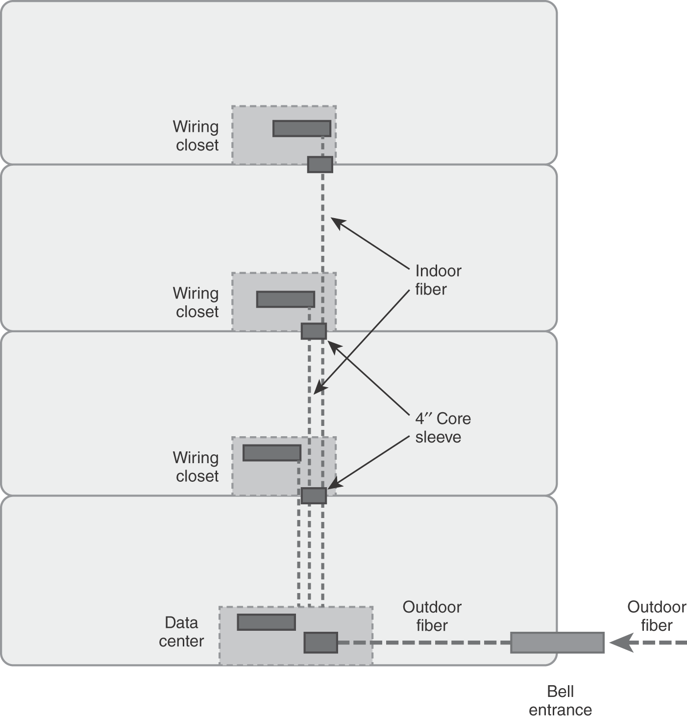
FIGURE C-1 Building cabling distribution viewpoint.
Design Approach
The following design criteria will be used as a guideline for designing a structured wiring system within this single building location:
- Building entrance cabling must be extended to the data center or equipment room if possible; otherwise, use multimode fiber cabling from the data center to each floor’s wiring closet to act as the building backbone cabling.
- Use single-mode fiber cabling for campus environments and long-haul interbuilding connections.
- Building backbone cabling should be multimode fiber, with 12 strands to each wiring closet from the data center. (Consider using 2 × 6-strand separately sheathed fiber optic cables.)
Note: If switches are stackable within the wiring closet, you need only one backbone connection if the link speed is high enough (e.g., 40 GigE backbone connection, etc.). - Wiring closets should be vertically stacked through the main building with 4-inch core sleeves providing a distribution pathway.
- Position wiring closets no further than 90 meters to a workstation outlet or about 295 feet maximum.
- If Voice over Internet Protocol (VoIP) is used, power the phone via a Power over Ethernet Plus (PoE+) Layer 3 switch. This eliminates needing a second, 4-pair unshielded twisted-pair (UTP) cable.
- Each workstation outlet will have two 4-pair UTP cables pulled and terminated onto two separate RJ-45 jacks using the EIA 568B pin configuration.
- Patch cables should be 10 feet at the workstation outlet end using the EIA 568B pin configuration.
- Patch cables should be 4 feet in the wiring closet end for direct connectivity from patch panel to Layer 2/Layer 3 switch using the EIA 568B pin configuration.
- The drop ceiling will act as the air conditioning return duct; hence, plenum-rated sheathed UTP cables are needed, as opposed to polyvinyl chloride (PVC) plastic-sheathed UTP cables. PVC is not fire retardant and will catch fire and melt plastic.
When designing a horizontal workstation cabling system, first obtain a floor plan. The second step is to calculate the maximum physical distance from the wiring closet to the workstation outlet. This ensures you are within distance limitations for the type of cabling used. FIGURE C-2 shows a sample building floor plan and design approach.
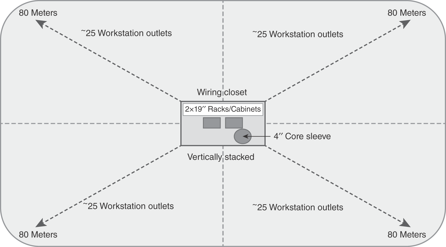
FIGURE C-2 Building floor plan design approach.
Components of a Structured Wiring System
A structured wiring system has six foundational building blocks—building cabling entrance, data center or equipment room, backbone cabling, telecom room/wiring closets, horizontal cabling, and workstation/office location. This primer reviews each building block and provides guidelines for what you need to assess, design, and implement them.
Building Cabling Entrance
Prior to the AT&T divesture and breakup in 1984, the term Bell entrance referred to the bundled, twisted-pair cabling entering the building with proper electrical protection and grounding. The actual physical path into a building was a metallic conduit entering into the bottom floor of a building. Inside of the metal conduit was the bundled, twisted-pair cabling from the central office telephone switch. With new construction, the building entrance is a metallic conduit path providing a physical path into the building. Service providers install fiber optic cabling bundling voice, TV, and Internet. A cable path or conduit path may be needed to extend from the Bell entrance to the data center or equipment room.
The building has a single metallic conduit that acts as the building entrance for outdoor cabling. A data center resides on the basement floor where all cabling is terminated. Termination of a copper wire means a physical connection is made between the actual copper wire and wiring block (e.g., a 66-block for terminating voice copper cables or a 110-block for terminating data copper cables onto RJ-45 patch panels). The local service provider has brought in two separately sheathed fiber optic cables with multiple strands each. These fiber cables support bundled voice, data, and Internet connectivity for the entire building.
The outdoor fiber cabling must extend to the data center or equipment room where the fiber optic cabling can be terminated with SC connectors in a fiber optic patch panel. This is shown in FIGURE C-3.
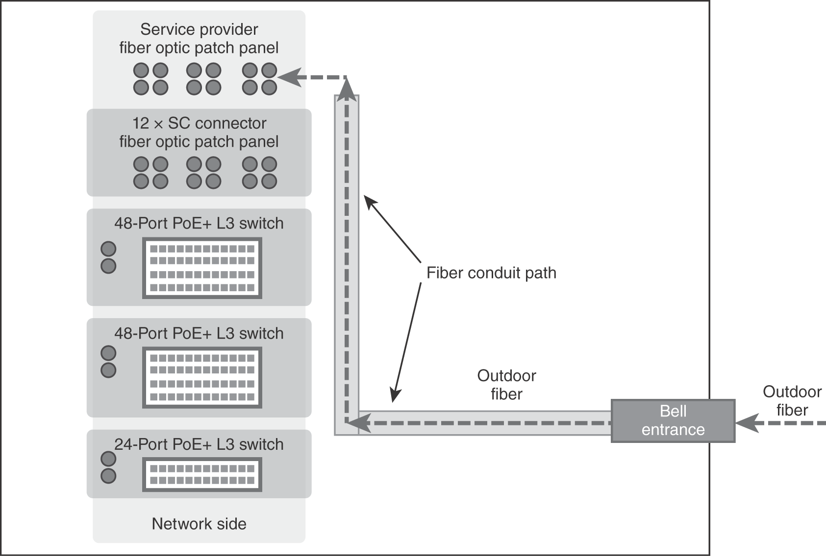
FIGURE C-3 Building backbone cabling viewpoint.
Data Center or Equipment Room
The building will typically have a clean room, data center, or equipment room. This centrally located room will house computer equipment, network equipment, and the building’s backbone cabling system. Battery backup, redundant network switches, and generator backup power are part of the environmental controls needed to support a highly available network.
Note the network side rack on the left in FIGURE C-4 and the workstation cabling side rack on the right. Cross-connections are made via an RJ-45 patch cable between the Layer 3 PoE+ switch and the workstation cabling.
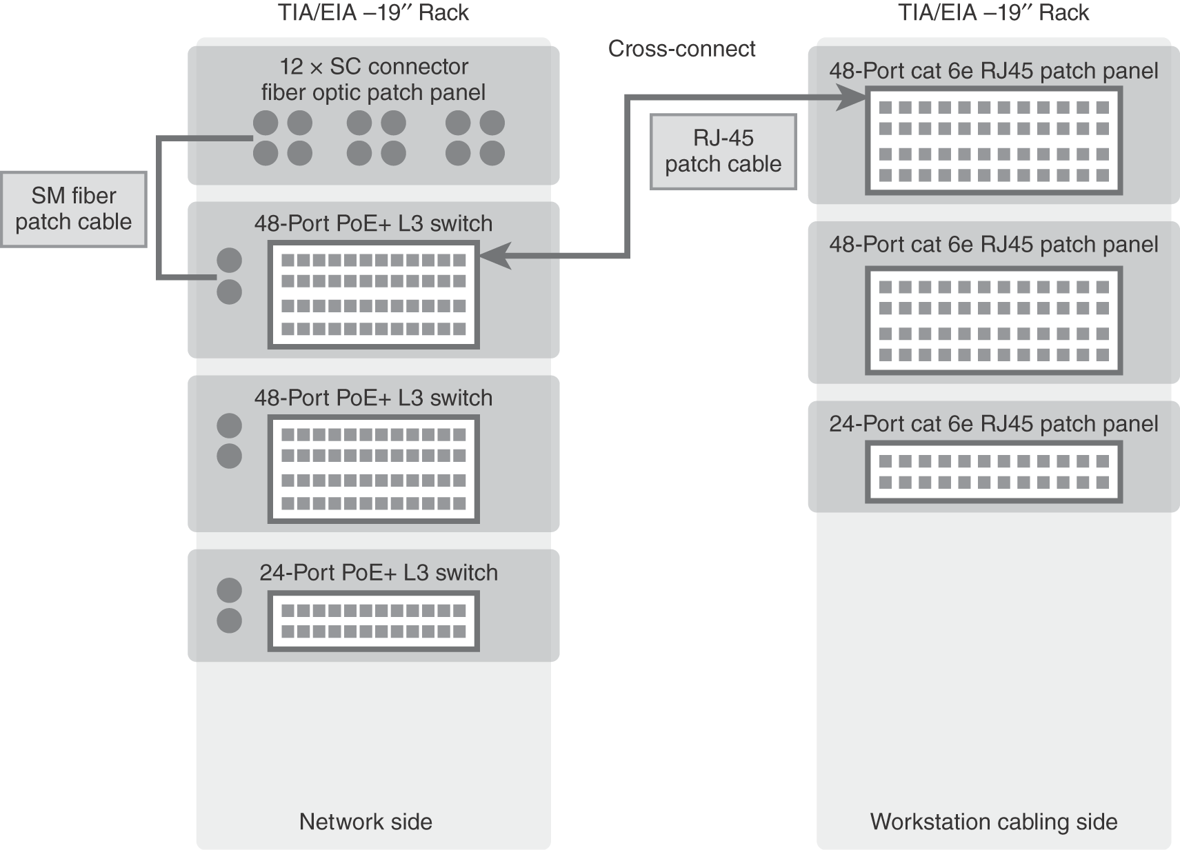
FIGURE C-4 Data center rack elevation viewpoint.
Backbone Cabling
If VoIP is used, there is no need for copper backbone cabling unless analog phone lines are needed in various locations. Multimode and single-mode fiber cables are typically installed from the data center to each wiring closet, providing long-term growth and high-speed backbone connections (10GigE, 40GigE, 100GigE, etc.). Bundled unshielded twisted-pair cabling in 25-pair, 50-pair, or 100-pair is needed only if a wired digital phone system is utilized.
- Multimode optical fiber cabling—850 nm laser-optimized 50/125 μm is recommended; 62.5/125 μm and 50/125 μm are suggested using SC connectors and patch panels.
- Single-mode optical fiber cabling—8–10 μM/125 uM is suggested using SC-connectors and patch panels.
Fiber connectors include the following and have different applications:
- LC (Lucent connector)—Has a square-shaped connector that locks into a fiber transceiver, typically in a duplex configuration (e.g., two square-shaped connectors). LC connectors are used for single-mode fiber and very long distances or high-speed transmissions (e.g., SONET, OC-X speeds, etc.).
- ST (straight tip)—Has a round, bayonet-style connector that pushes in and turns to lock into place, typically in a duplex configuration. ST connectors are primarily used for multimode fiber strands.
- SC (square connector)—Has a square-shaped connector that locks into a fiber transceiver, typically in a duplex configuration. SC connectors are used for single-mode and multimode fiber strands, depending on the electronics that are used. For new construction, the SC connector is the default choice, though ST connectors might be required for existing equipment. Angled physical connector (APC), ultra physical contact (UPC), and MT-RJ miniature-sized connector are part of the SC connector family.
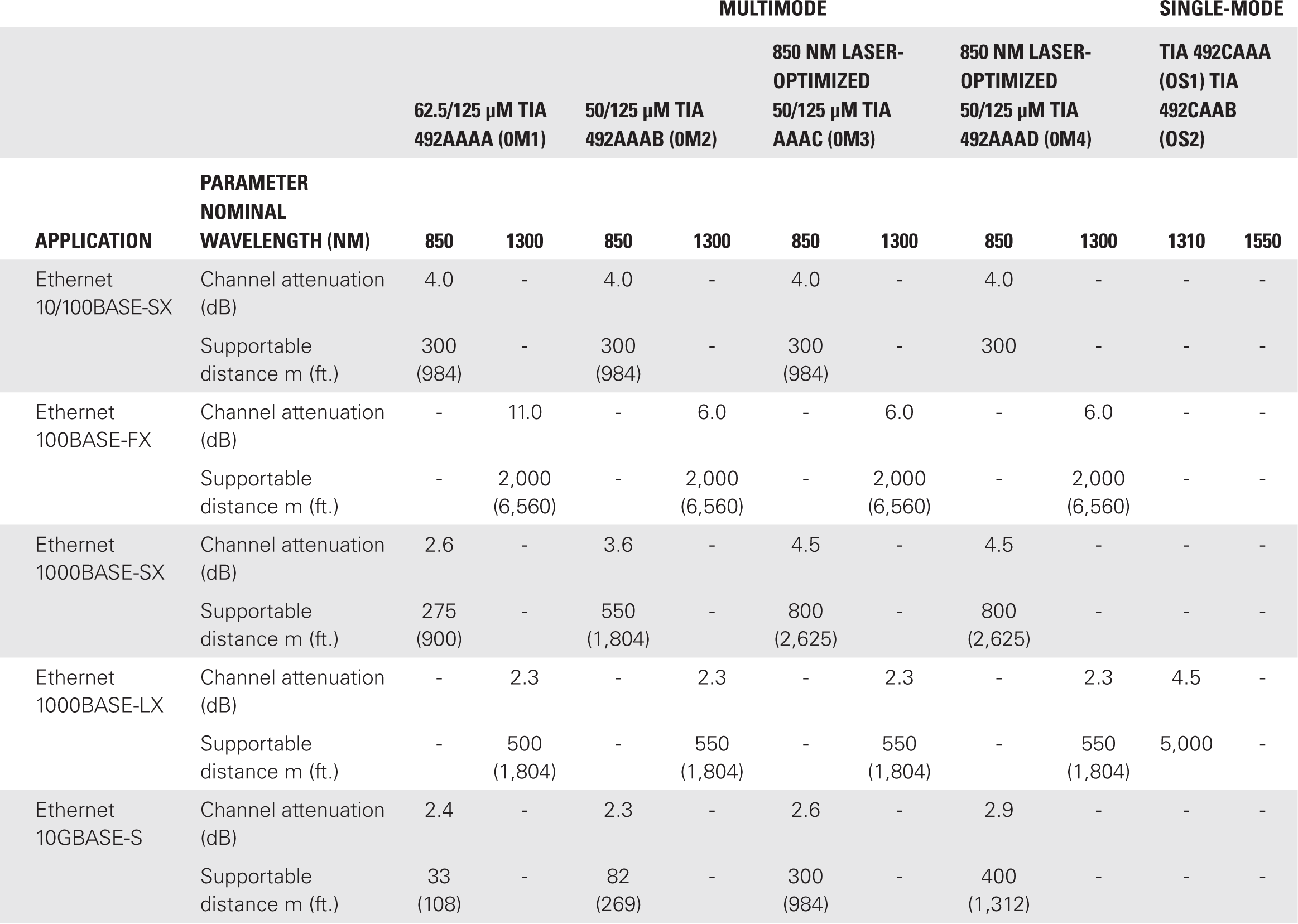
TABLE C-1 summarizes the distance limitations for various fiber optic cabling and 850 μM and 1300 μM wavelengths.
Telecom Rooms/Wiring Closets
Telecom rooms or wiring closets are centrally located on floor plans. They are needed to support backbone cabling and horizontal workstation cabling and LAN equipment. In addition, LAN switches are installed here to provide workstation connections to the LAN via a patch cable. Wireless access points (APs) connect to LAN switches in the wiring closet supporting Wi-Fi user connectivity. Wiring closets are typically positioned to be no greater than 90 meters to the furthest workstation outlet. This distance will support high-speed Ethernet connections to the workstation outlet on 4-pair UTP cabling.
Horizontal Cabling
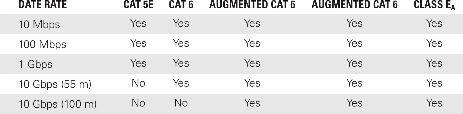
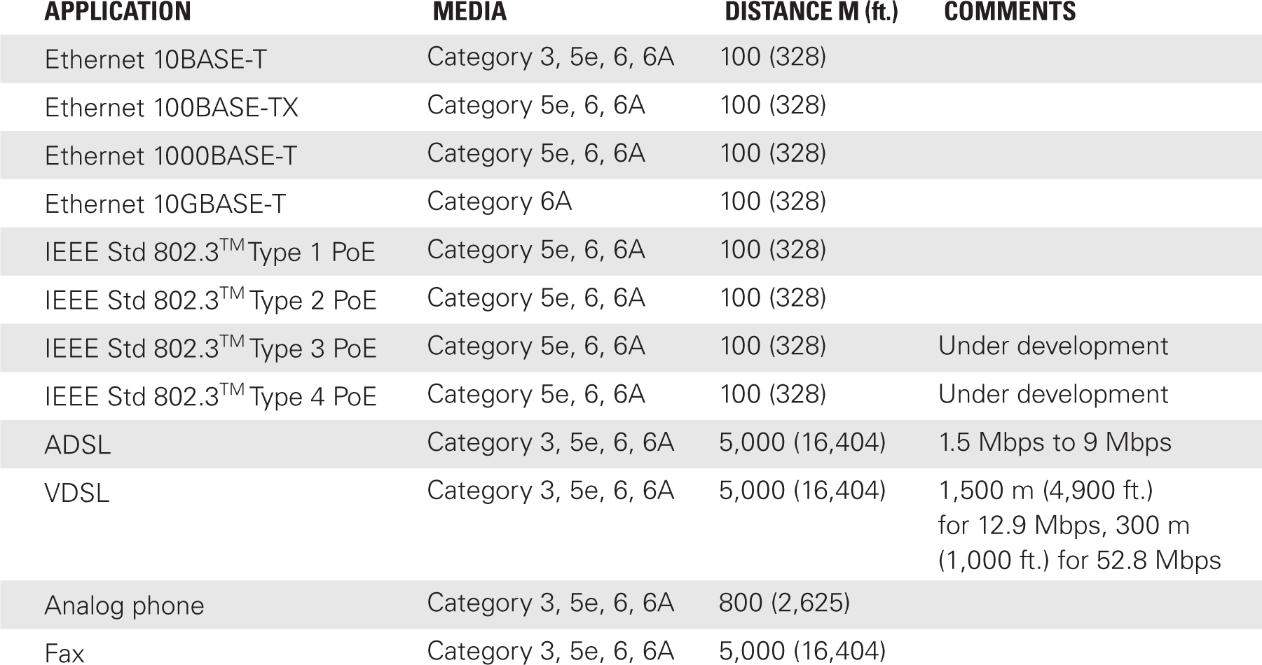
This is the workstation cabling that emanates from the closest wiring closet to the workstation outlet. For ceilings that have air conditioning flow, plenum-rated cabling sheaths are required for installation above the ceiling. You will need to pull and install 100-Ohm, 4-pair UTP cabling in Cat 3, 5, 5e, 6, and 6e specifications to support voice and data connectivity. Transmission speeds and distance limitations are shown in TABLES C-2 and C-3, respectively.
Workstation/Office Location
Each 4-pair UTP workstation cable should be terminated onto an RJ-45 connector at the workstation outlet. Using a consistent pin configuration for voice and data jacks, the RJ-45 connector and corresponding patch panel in the wiring closet must be wired the same (i.e., both ends must use the same RJ-45 pin configuration as EIA 568A or EIA 568B to ensure end-to-end connectivity). FIGURE C-5 depicts a block diagram that includes the wiring closet, the horizontal workstation cabling, and the workstation outlet.
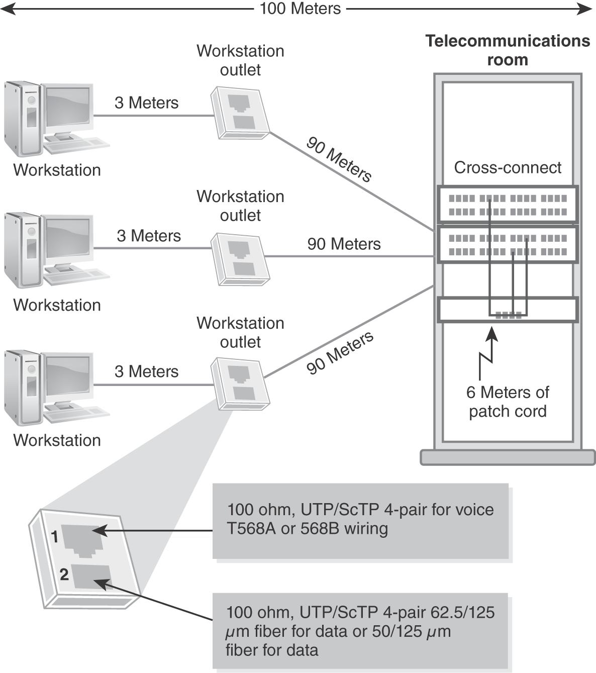
FIGURE C-5 Block diagram of structured wiring to workstation outlet.
Installation, Testing, and Documentation of a Structured Wiring System
With any structure wiring system, installation, testing, and as-built documentation are a must to have as part of the overall system.
Installations must be in compliance with BICSI, TIA, EIA, low-voltage electrical, and local building codes. All structured wiring system installations must pass a fire inspection by the county fire marshal as part of new construction building occupancy permit releases.
All UTP cabling must be continuity tested, end-to-end from the workstation outlet through the entire cabling infrastructure to the workstation patch panel in the wiring closet. Distance, attenuation, signal-to-noise, crosstalk, and continuity testing are required for all UTP cable pairs.
All fiber optic cabling must be continuity tested, end-to-end from the ST fiber patch panel all the way to the data center where the main equipment room ST fiber patch panel is. An optical time domain reflectometer (OTDR) is needed to measure distance, attenuation, and continuity for each fiber strand.
A certified cabling system requires a battery of tests performed on the installed cable plant. This include testing for distance, continuity, attenuation, noise, and GigE network transmission speeds on UTP. This type of testing assures that the newly installed cabling system will support the electrical specifications of the electronics that are installed, including VoIP and GigE, to the workstation outlet. Fiber optic testing includes measuring distance, attenuation, and splice points using multiple optical wavelengths.
Technical TIP
When performing a certification test on unshielded, twisted-pair transmission media, the following tests should be performed along with requirements for the cable plant’s “as-built” documentation:
- Attenuation—This test sends a signal out onto the cable and measures the amount of signal loss at the other end. This is commonly referred to as insertion loss given the length of the cable.
- Crosstalk—This is a condition in which the signal from an adjacent pair of unshielded, twisted-pair cables interferes with another signal on a different pair of unshielded, twisted-pair cables. It is commonly referred to as alien crosstalk.
- Length—This is the actual distance of the cable that is measured to ensure it is within the specifications of the IEEE 802.3 and TIA/EIA 568 telecommunication wiring standards.
- Pin configuration—This test will verify that the proper wire was terminated in the correct pin number on an 8-pin, RJ-45 connector.
- Propagation delay—This is the amount of time it takes for the signal to reach the end of an unshielded twisted-pair. This test is performed in conjunction with the length or distance measurement test. Propagation delay is directly proportional to the nominal velocity of propagation (NVP).
- Return loss—This test measures any signal reflections that are caused by an impedance mismatch from end to end. Impedance is the same as resistance measure in Ohms. The impedance of the cable must match that of any elements connected to the cable. This matching maximizes the signals’ strength. An impedance mismatch reflects some of the signal strength, thus making the signal weaker. This is measured in decibels (dB). This test is important for certifying UTP used for Gigabit Ethernet (1000Base-T).
- Signal-to-noise ratio (SNR)—This test, used in science and engineering, compares the level of a desired signal to the level of background noise. SNR is defined as the ratio of signal power to noise power, often expressed in decibels.
- Smartjack—This is a device installed between the service provider’s demarcation point and an internal network. The smartjack is equipped with different connectors and terminations allowing for multiple different methods of connectivity (e.g., RJ-45 connector, etc.).
All physical cables (UTP or fiber), when terminated onto a patch panel, must be properly labeled on both ends of the cable.
All workstation outlets will have a corresponding voice RJ-45 jack and data RJ-45 jack number, which need to correspond to an equivalent RJ-45 jack in the wiring closet RJ-45 patch panel.
All cabling documentation should be provided in a spreadsheet or database such that the final as-built documentation can be reviewed and accepted with official test results.
Additional References and Content Regarding Structured Wiring Systems
- Building Industry Consulting Services Industry (BICSI)—A nonprofit organization dedicated to the education, training, and professional certification of engineers in low-voltage, structured cabling systems. The BICSI organization maintains and manages the Registered Communications Distribution Designer (RCDD) professional certification.
For more information: https://www.bicsi.org - TIA/EIA-568—A family of telecommunications standards from the Telecommunications Industry Association. The standards contain requirements for designing and installing a structured cabling system for consumers, businesses, and commercial building environments.
- The structure for commercial building cabling is specified in TIA-568.0-D.
- Performance and technical specifications for twisted-pair cabling systems are specified in TIA-568-C.2.
- Performance and technical specifications for optical fiber cabling systems are specified in TIA-568.3-D.
TIA/EIA standards were updated in 2015 under revision D.
For more information: https://www.tiafotc.org/ansi-tia-568-d/
- Anixter—A leading structured cabling system; low-voltage electric distributor; and supplier of UTP and fiber optic cabling, patch panels, RJ-45 connectors, and fiber optic ST and SC connectors. Anixter provides a complete structured cabling system primer and overview.
For more information: https://www.anixter.com/en_us/resources/literature/techbriefs/the-six-subsystems-of-a-structured-cabling-system.html - Black Box—Another leading structured cabling system; low-voltage distributor; and supplier, installer, and tester for UTP and fiber optic cable plants. Cables, patch panels, connectors, tools, and testers can be purchased from Black Box.
For more information: https://www.blackbox.com/en-us/solutions/solutions/by-technology/cables-and-infrastructure