Internetworking
As LANs grow and expand, so does the need to interconnect them. LANs have a physical distance and node limitation. LANs that support workstations and servers are designed to optimize performance. Workgroup LANs typically share files and information mostly with each other; hence, network traffic should be isolated within the workgroup. Internal traffic that leaves the workgroup LAN traverses the building or campus backbone network to designated servers. External traffic that leaves the workgroup LAN traverses through the public Internet.
Internetworking is a term used to describe connecting LANs together, as shown in FIGURE 3-22. There are several ways to connect LANs such that network traffic can traverse between them. LANs communicate using protocols and the OSI model. Different network devices interoperate at different layers of the protocol stack. A protocol stack is how software operates at different layers of the OSI model. Internetworking LANs must follow the OSI model protocol stack definition. Thus, network devices must operate at either the Data Link Layer or the Network Layer.

FIGURE 3-22 Internetworking at the Data Link Layer or Network Layer.
One of the most common uses of enterprise digital networks is to support enterprise applications. The vast majority of enterprise applications consist of a central server that handles data storage and handling, and local client software that handles the user interface. Users interact with the enterprise applications via local software running on client devices that use a network to connect to, and request services from, one or more servers. This application architecture is called client/server architecture and depends on client/server internetworking.
Client application software doesn’t always operate in a client/server model. In some cases, such as sharing files, running messaging applications, or even collaborating on business workflow operations, direct communication with one another may be better than using a central service. Clients that communicate with one another directly are called peers of one another. Peer-to-peer internetworking is the use of an enterprise network for peers to exchange messages without depending on a central server to manage connections or message handling. Most of today’s digital networks can support client/server and peer-to-peer communications.
Internetworking at the Data Link Layer requires a network device known as a bridge. The MAC layer implies the Media Access Control layer within the Data Link Layer of the OSI model. Within this layer, the 6-byte MAC address is examined within the Ethernet v2.0 or IEEE 802.3 CSMA/CD frame to make a forwarding or nonforwarding decision. A bridge creates the MAC address table by learning where all the MAC layer addresses are of other devices. The bridge listens to received traffic and remembers the port on which the traffic arrived from each MAC address.
Internetworking at the Network Layer requires a network device known as a router. The Network Layer implies a Network Layer address must be present within the Network Layer of the OSI model. Within the Network Layer resides a Network Layer address, which is like a zip code that is used for routing mail and letters through the U.S. Postal Service. Within this layer, the Network Layer address or IP address is examined within the IP packet found at the Network Layer. Routers build IP routing tables that define path determination for IP packets. A packet is a chunk of a message. IP networks are configured on physical ports of the router. Routers forward IP packets based on where that IP network is physically located and the physical port or interface that connects to it.
Technical TIP
An internal network that only employees can access is called an intranet. An organization’s intranet typically allows users to access internal files and resources pertinent to the organization and its employees only. For this reason, access to an intranet requires proper security controls. The terms Internet and intranet are often confused.
Many organizations maintain their own internal network of connected networks. An internal network is accessible only from locations within an organization (i.e., behind the Internet ingress/egress firewall where the organization’s dedicated Internet access link resides).
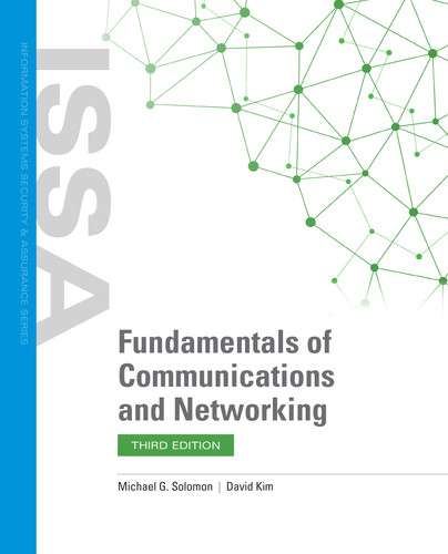
The public Internet is a global worldwide network that uses the Internet Protocol (IP) for communications. An intranet is a private network within that organization’s IP network infrastructure. An extranet is a remotely accessible network that an organization makes accessible to its business partners and suppliers through the public Internet. An extranet is also a secure network that requires proper access controls and authentication prior to granting access. FIGURE 3-23 illustrates the differences.
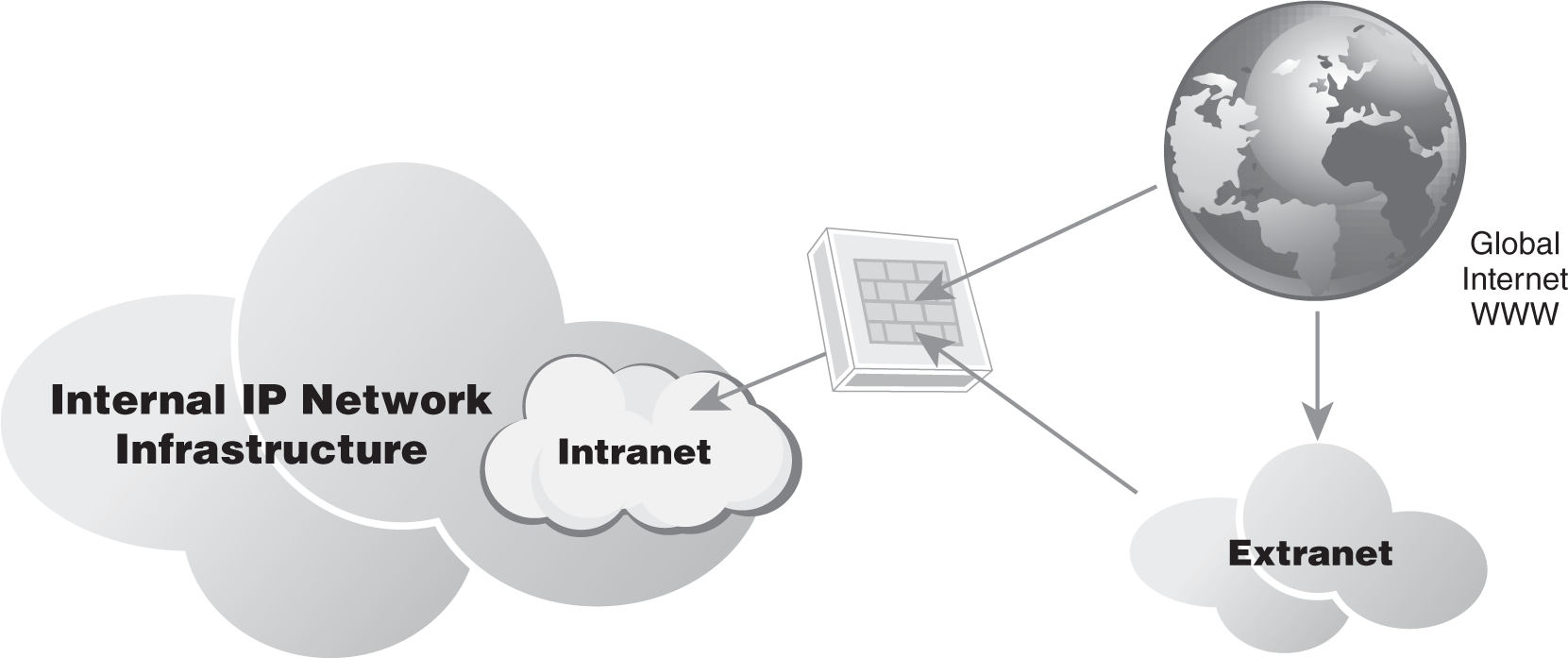
FIGURE 3-23 Intranets and extranets.
There are several options for interconnecting multiple networks, which vary based on functional, technical, and security requirements. Each option provides different levels of functionality with varying levels of performance, manageability, and security. Today, manufacturers incorporate MAC layer bridging and Network Layer routing within the same hardware device. In addition, embedded firewalls and security countermeasures also are incorporated into the software functionality of combined bridges and routers. Each organization must carefully select the best product to meet its specific needs and financial parameters.
Internetworking with Bridges
The easiest way to interconnect two networks is to place a MAC layer bridge in between the two networks. A simple network bridge is a device with two network interface cards so that it can connect to both networks. A bridge operates at the OSI Data Link Layer or Layer 2. That means it interacts with the Physical Layer and the Data Link Layer. A bridge can read the Media Access Control (MAC) layer address of each Ethernet frame to make a forwarding or filtering decision. The MAC address is a 6-byte address that is burned into a chip on the network interface card. Each MAC address is unique. A bridge examines the MAC address of each frame received, and then makes a filtering or forwarding decision based on the MAC address forwarding table.
Because a bridge has two or more network interface cards, it learns where the MAC addresses are on each port. The bridge then builds a table of all the MAC addresses learned and what port they are located on. This is how a bridge filters or forwards an Ethernet frame to an appropriate port. MAC layer bridges (see FIGURE 3-24) can have static address tables, or they can dynamically build tables.
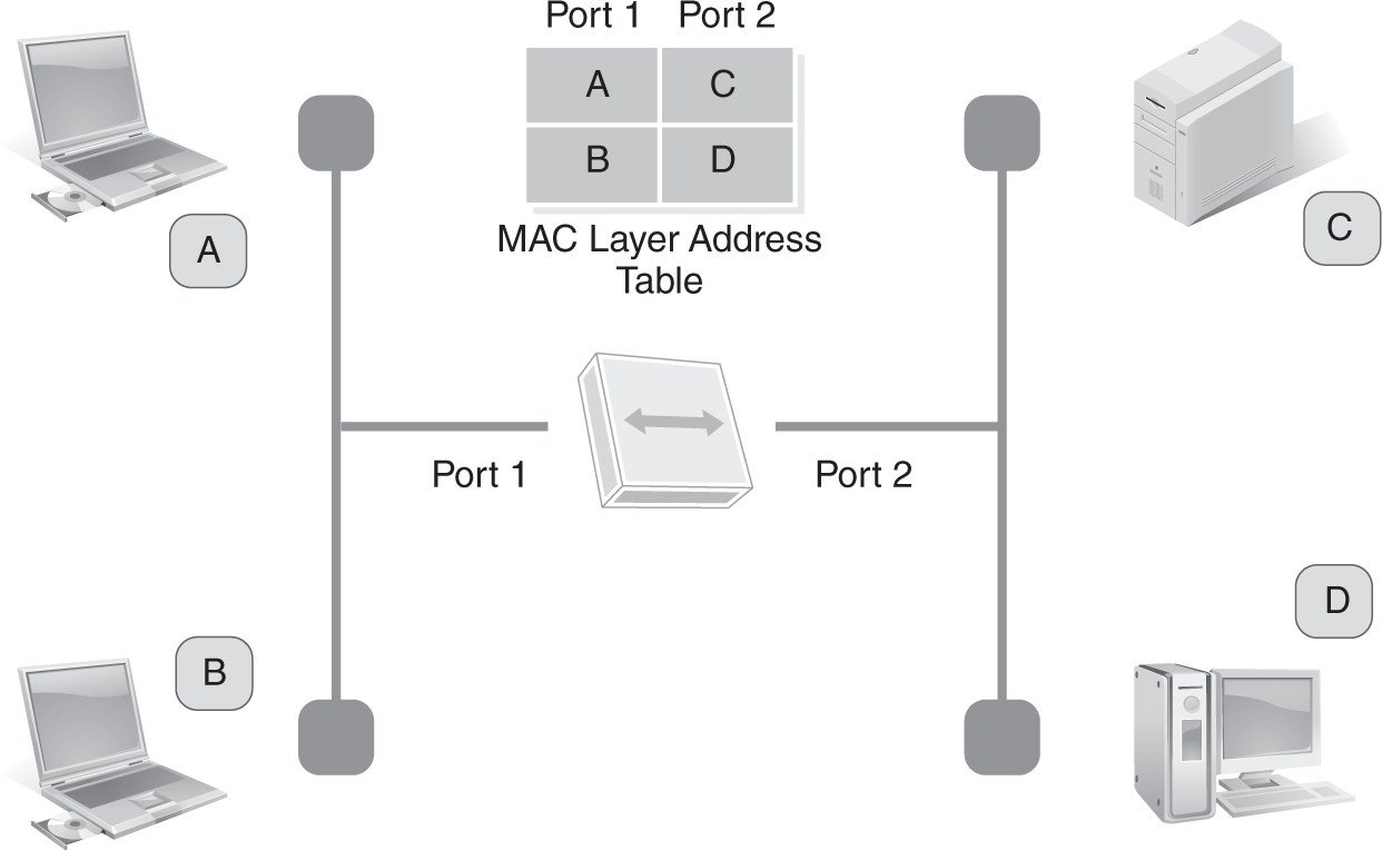
FIGURE 3-24 MAC address forwarding table.
Internetworking with Switches
A switch is essentially a bridge with more than two ports. A bridge generally connects two networks. A switch often has the ability to connect many devices and networks. Switches operate as an OSI Layer 2 device. They use MAC addresses and build address tables of devices connected to each physical port. Switches that connect multiple devices or networks keep track of MAC addresses on all ports. When the switch sees an Ethernet frame destined for a specific MAC address, it forwards that frame to that port.
There are two kinds of LAN switches. A Layer 2 switch operates at the Data Link Layer and examines the MAC layer addresses of Ethernet frames. Using this information, filtering and forwarding tasks are performed by the switch. Layer 2 switches come in 12-port, 24-port, and 48-port versions providing individual Ethernet LAN segments per port. This maximizes performance and provides a dedicated Ethernet LAN segment per device that connects to that port. A Layer 3 switch operates at either the Data Link Layer or Network Layer. Layer 3 switches typically have software that lets them function like a Layer 2 switch or multiport bridge. Layer 3 switches usually operate at the Network Layer that examines the network layer address within the Ethernet frame.
The IP addresses typically are found in the Network Layer of the packet. An IP address is like a zip code for mailing a letter. It has both a network number and a host number, which is used to route IP packets to the appropriate destination IP network. A Layer 3 switch can look up the destination IP network number in its IP routing table, and then make a path determination decision. A Layer 3 switch provides each device connected to its ports with its own Ethernet LAN segment. Layer 3 switches typically have resiliency or a redundant path connection, also called a redundant circuit, to a building or campus backbone network. You’ll learn more about resiliency later in this chapter. With Layer 3 switches, routing and alternate paths are typically implemented.
Internetworking with Routers
A router operates at the Network Layer. It is the same thing as a Layer 3 switch, except it’s typically used for wide area network circuit connections, campus backbone connections, and building backbone connections. Routers can make intelligent decisions on where to send packets. Instead of just reading the MAC address and forwarding a packet based on a forwarding table, routers can see the packet’s Network Layer address or IP address. The Network Layer address contains information about the destination network number and host number. In essence, routers perform a path determination calculation to find the best path for the IP packets to traverse.
Routers are very powerful network devices. Typically they have redundant processors and plenty of memory, and can support lots of network connections. These network connections can be wide area network connections or local area network connections. Of course, this increased functionality has a cost. It takes longer for a router to examine a packet than for a Layer 2 switch or bridge. High-traffic networks may notice performance issues with multiple routers examining each IP packet to make a path determination decision. (See FIGURE 3-25.) For lower-traffic networks, a router can help ensure network packets flow only to their destination network. This can reduce overall network congestion and increase security by keeping workgroup LAN traffic isolated. Ensuring packets travel only to their destination networks makes it harder for unauthorized users to intercept the traffic. Many organizations that are concerned with network security often create smaller networks. They use routers to reduce the traffic as well as the distance network traffic has to traverse.
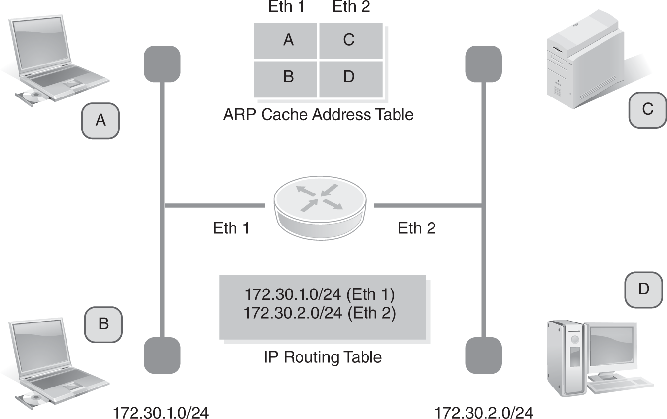
FIGURE 3-25 Router ARP cache table and IP routing table.
Internetworking with a Bridge/Router
One problem with regular routers is that they can examine packets only in formats they understand. That means all nodes on the network must use protocols the routers understand. This makes it harder to connect networks that use different protocols. A device that can act as a bridge or router is often called a brouter. This is the same thing as a Layer 3 switch with Layer 2 bridging software. Depending on the LAN protocols that exist, networks may need to support nonroutable and routable protocols. A nonroutable protocol is one that does not have a Network Layer address. A routable protocol is one that has a Network Layer address that is routable. A brouter will then bridge Ethernet frames that are nonroutable and will route IP packets that are routable. This requires that IP routing be enabled in the device. A brouter is a more flexible and powerful internetworking device for networks, given that it can interconnect LANs at the Data Link Layer or Network Layer.
Internetworking with a Gateway
The final internetworking device found in networks is the gateway. A gateway interconnects two networks that use different protocols. Unlike a brouter, the gateway translates network packets from one network protocol to another. The main job with a gateway is to translate all incoming packets to a protocol compatible with the destination network. Gateways are commonly placed at entry and exit points of a network. They commonly run either as software on a computer or as a device that performs the same functions as a router.
Gateways were common during the IBM SNA mainframe era, when 3270 terminal emulation was performed in LAN-attached PCs and workstations. IBM’s SNA protocol was widely used for mainframe data processing and communications; 3270 terminal emulation was the language that IBM terminals used to communicate to the mainframe computer. Using a common gateway, PCs and workstations could emulate and communicate via the SNA protocol using TCP/IP as a Transport and Network Layer protocol. Gateways allow IP-connected PCs and workstations to communicate with an IBM SNA mainframe device.