Layer 3 Network Redundancy and Resiliency
A network’s capability to maintain a certain level and quality of service at all times, regardless of faults and interruptions, is resilience. In other words, the network is resilient to failure. For the network to be resilient, its Physical Layer media, its Layer 2 network access functions, and its Layer 3 forwarding and addressing functions must have hot-swap redundancy ready to take over when there is a network or system failure. However, redundancy and resiliency are not the same. Redundancy is a form of resilience.
Configuring Resilience
Redundancy can provide resiliency, but only through the installation of additional devices, systems, or links that are able to come online when the primary device, system, or link fails. Redundant devices also can be used in a load-sharing situation, which means they are already online and ready to take on the entire load, if needed. However, when certain devices fail, such as a power supply unit (PSU) installed in a router as a backup to its main PSU, the backup devices must be configured or have the power to fully replace the failed part. Too often, the backup device cannot support the load of the primary device, which means the backup part is worthless.
Creating resiliency on a network makes that network fault tolerant. However, just having redundant devices or links won’t create resiliency unless you have configured your routers to use those devices or links should the primary link or device fail.
The first steps in configuring a resilient network are to determine how resilient the network needs to be and just where in the network resilience is needed. Do you need resiliency in the core, distribution, or access network domains? Where is resiliency needed most? Typically, adding resilience to a network can be accomplished at little cost, because most network switches and routers already support the basic foundational solutions for resiliency:
- Backup or dual power supplies—Critical network devices can be installed with dual power supplies in the event of failure.
- Battery backup and uninterruptible power supplies (UPSs)—Needed for electrical outages or failure of the primary electrical source. Battery backup is needed to power down IT assets or continue operations.
- Diesel generators—These are used for electrical power backup in the event of a catastrophic electric power outage.
- Backup router CPU processors and modules—If the primary CPU processor fails, a secondary CPU processor is ready.
- Alternate network links—Alternate links are used for redundancy and high-availability connections.
- Alternate and redundant wiring and fiber optic cabling paths—These are used in the event of a cable cut.
- Redundant core, distribution, or access switches—A second chassis is installed and fully integrated into the core, distribution, or edge network for high availability.
- Virtualization of routers and their switching functionality—To support collapsed backbones and internetworking between LANs. A virtual switch is created in software of a core or distribution switch. A virtual switch allows a physical switch to have more than one logical switch for redundancy and alternate paths to other virtual switches.
The easiest steps to take are to run redundant links between the switches and implement Rapid Spanning Tree Protocol (RSTP) or Multiple Spanning Tree Protocol (MSTP). RSTP and MSTP will prevent any Layer 2 broadcast loops and configure the timer settings to eliminate delays. Technology such as Link Aggregation Control Protocol (LACP), which configures link aggregation, allows the network devices and protocols to believe that the multiple links between devices are just one link. When one link fails, to the network services there was seemingly no failure at all. This is true even if the failure is a connection on the router or switch. Cisco IOS has a resilient configuration feature. When enabled, it allows the router to keep a current copy of its configuration to guard against attacks that attempt to erase its memory.
Routing Protocol Resilience
First Hop Redundancy Protocols (FHRPs) are routing protocols that can support the resilience of a network, but the ability of the router and its routing protocol to recover quickly is dependent on the configuration of the router, the routing protocol, and the links connected to the router. Configuring the router for load balancing can add to the resilience of the network, but only if the router is connected to equal-cost links of equal capabilities. Otherwise, if a lower-cost link (bandwidth) fails, the higher-cost link may not be able to carry the entire load. The router may need to be configured to carry only the most vital traffic when the primary link fails.
Two examples of FHRPs are designed specifically to support and provide network resilience: the industry standard Virtual Router Redundancy Protocol (VRRP), which clusters multiple routers into a single virtual router, and Cisco’s proprietary Hot Standby Routing Protocol (HSRP).
Virtual Router Redundancy Protocol (VRRP)
VRRP version 3 (at the time of this writing) supports IPv4 and IPv6 and is the standard redundancy protocol. VRRP routers hold an election based on priority values and select one router to be the master router. All other routers are backup routers. Each router is configured with the same virtual router identifier (VRID). Using the VRID arrangement, VRRP also can provide load balancing on each router’s links.
As illustrated in FIGURE 8-6, the end devices are configured for the virtual router, which isn’t a real device. Instead, they are switched to a virtual IP address that is linked to the master router. Should the link to the router fail, or the master router itself fail, the same virtual address now links to the backup router, which has assumed the role of the master router.
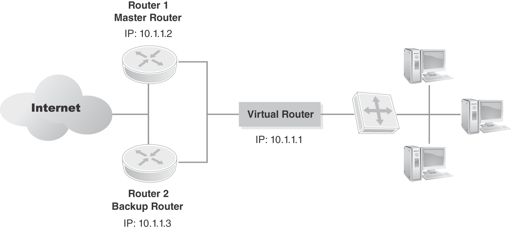
FIGURE 8-6 VRRP creates a virtual router that is the primary router for its network.
The level of resiliency provided by the IETF VRRP standard, RFC 5798, is dependent on how fast the backup router is able to assume the role of master router. If there is any downtime for the end devices, it amounts to only the time needed for the switchover. There is some convergence time involved. Master routers send periodic multicast VRRP advertisement messages that the backup routers listen for. When a backup router doesn’t “hear” the master messages within a certain time interval, based on its knowledge of all the other backup router priority settings, it converges and becomes the master router. VRRPv3 provides subsecond convergence.
Hot Standby Routing Protocol (HSRP)
In computing, the word hot means that a device or service is powered, running, and ready to replace another device or service should it fail—as in “hot swap.” HSRP is a software virtualization solution from Cisco Systems that allows a second core or distribution router to be a virtual duplicate of the primary switch and its configuration. When configuring a network for resilience, this meaning carries forward. The purpose of HSRP, which is a Cisco proprietary protocol, is to provide a hot swappable (e.g., ability to remove an interface module without powering down the router or switch) IP gateway to end devices, such as desktop PCs, laptops, and servers, without installing another physically redundant device. Similar to VRRP, HSRP provides for a constant, virtual gateway to end devices.
Gateway Load Balancing Protocol (GLBP)
Gateway Load Balancing Protocol (GLBP) is a Cisco proprietary protocol that improves on the functionality of HSRP. Although HSRP is useful for setting up a virtual IP address to be used as a redundant gateway, it lacks some features. The main feature that GLBP adds is the ability to load balance traffic over multiple routers. HSRP uses an active/standby model in which a virtual IP address is managed by one router, the active router, and is always the primary gateway unless the router or link goes down, in which case a standby takes over that role and becomes active.
With GLBP, it is possible to load balance across multiple routers using a single virtual IP address and multiple virtual MAC addresses. A GLBP group is created, each member is configured with the same virtual IP address, and all of the routers participate in forwarding packets. The members use hello messages, sent every 3 seconds, to communicate with one another. The members elect one gateway to be the active virtual gateway (AVG) for the group, kind of like the IP default gateway router. The AVG then assigns a virtual MAC address to each group member (router). This mapping allows each router to act as active virtual forwarders (AVFs) for their virtual MAC address, like a network traffic cop.
The AVG answers Address Resolution Protocol (ARP) requests for the virtual IP address. The AVG then load balances by replying to the ARP requests with different virtual MAC addresses of the respective AVFs. The AVFs then forward on the packets.