Advanced Networking Devices
There are many network devices and appliances that can provide a specific function or enhancement to an IP data network. This section discusses advanced networking devices and explains what they do, what unique functions they provide, and where to implement them in a network. There are three types of advanced networking devices presented in this section:
- Advanced switching devices—These are next-generation Application Layer switches that can support backbone, distribution, and edge network connections.
- Layered security appliances—These are next-generation compliance and security solutions that deliver security services both internally and externally to the network.
- Performance enhancing devices—These are appliances that can enhance or augment a network service or overall network throughput and performance.
Advanced Switching Devices
There are many network devices and appliances that can provide a specific function or unique feature. This includes advanced switching devices, such as the following:
- Multilayer switch—Data centers, server farms, and virtual environments aggregate applications and data. This creates a bottleneck where a many-to-one network connection must support large amounts of network traffic and bandwidth. This is exactly the function of a multilayer switch. Multilayer switches help distribute the network traffic on the network.
- Distributed switch—When designing a network, assessing use of switch processing power across more than one switch is part of network performance optimization. Multiple processor-controlled switching units can operate in a distributed manner. There is often a hierarchy of switches from the core, distribution, edge, and so on. A centralized host switch interconnects with distributed switches and edge switches where a large concentrations of users are.
What Is Multilayer Switching?
The multilayer switch is commonly found in data centers, server farms, and virtual environments. It operates at all layers of the OSI model. The multilayer switch performs functions up to the Application Layer (Layer 7). Multilayer switches function just like Layer 2 or 3 switches and routers but usually at much faster speeds (e.g., GigE, 10 GigE, etc.).
Layer 2 switches forward Ethernet frames based on the Layer 2 destination MAC layer address. Remember, multilayer switches can act like a Layer 2 or Layer 3 switch or router, including static routing and dynamic routing.
Multilayer switches and Layer 3 switches are different. Routers are better equipped for WAN interfaces and interconnecting core backbone network connections. Multilayer switches are more suited for server farms or where a many-to-one network chokepoint occurs. Multilayer switches can bring higher speed connections to servers and the endpoints that need to connect via Layer 2 or Layer 3 networking. FIGURE 9-12 shows a multilayer switching environment with Layer 2 and Layer 3 networking throughout.
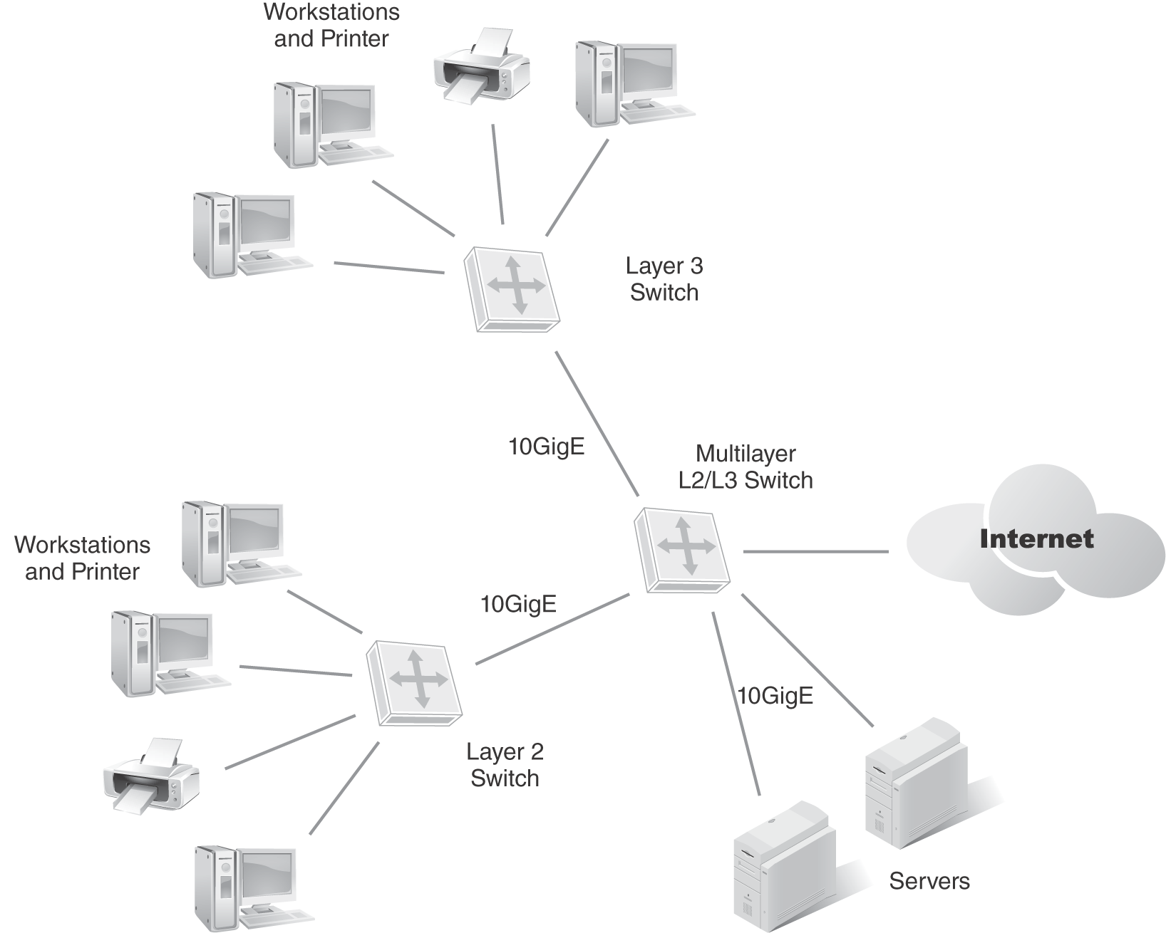
FIGURE 9-12 Multilayer switch placement.
What is Distributed Switching?
Depending on the physical architecture and design of your network, use of a distributed switching architecture may be needed. Backbone networks may not be as resilient as distribution or data center networks; hence, moving servers and users physically closer to one another can enhance performance and minimize network traffic from consuming backbone network bandwidth. A distributed switching architecture means you distribute high-speed Layer 3 switches in the distribution layer or edge layer to enhance network performance. This puts the burden on processing and network traffic locally to the network. FIGURE 9-13 depicts a distributed switching architecture where local edge switches perform high-speed switching, and backbone connections are supported with even faster network trunk at 10 GigE.
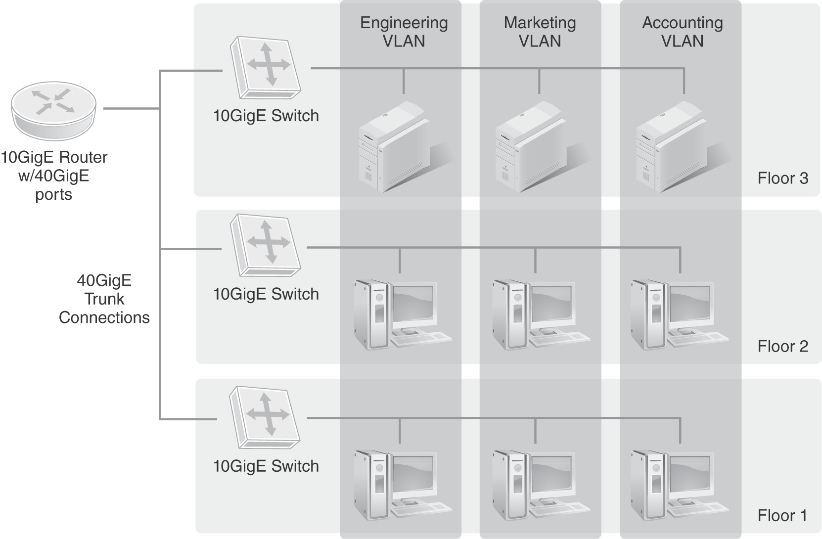
FIGURE 9-13 Distributed switching architecture.
Layered Security Solutions
IP data networks rely on layered security solutions. Layer 2 and Layer 3 networks have minimal security, hence the need for layered security around the network. Enterprise businesses and SMBs that host sensitive data have some or all of these security solutions. These solutions help organizations build a layered security architecture:
- AAA/RADIUS server—Enabling an authorization, authentication, and accounting (AAA) server supports an in-house authentication server solution. A RADIUS server can support internal system administrator access to IT assets and user authentication (e.g., two-factor authentication).
- Digital certificates—Website and portal authenticity is best validated with the use of digital certificates from certificate authorities (e.g., Verisign). In addition, use of encryption and the cypher key used are typically shown on the certificate. This reassures the website visitor that the browser connection is real and is being encrypted (e.g., HTTPS, etc.)
- IDS/IPS—Enabling an intrusion detection system (IDS)/intrusion prevention system (IPS) layer at the Internet ingress/egress point provides deep packet inspection and threat intelligence analysis to assist the filtering and notification—and in the case of an IPS, to attempt to prevent attacks, malware, and data exfiltration.
- Universal threat management (UTM) device—A network device that bundles layered security services into the same appliance for ease of implementation. A UTM device can embed antimalware monitoring, content filtering, firewall, intrusion detection, and spam protection into a single appliance.
- VPN concentrator—A network device usually located on a public-facing DMZ/VLAN such that IPSec VPN connections can terminate onto the VPN concentrator, where an encrypted tunnel provides secure data transmission.
FIGURE 9-14 depicts remote users and different endpoint devices remotely accessing the network using IPSEC VPNs for encrypted communications.
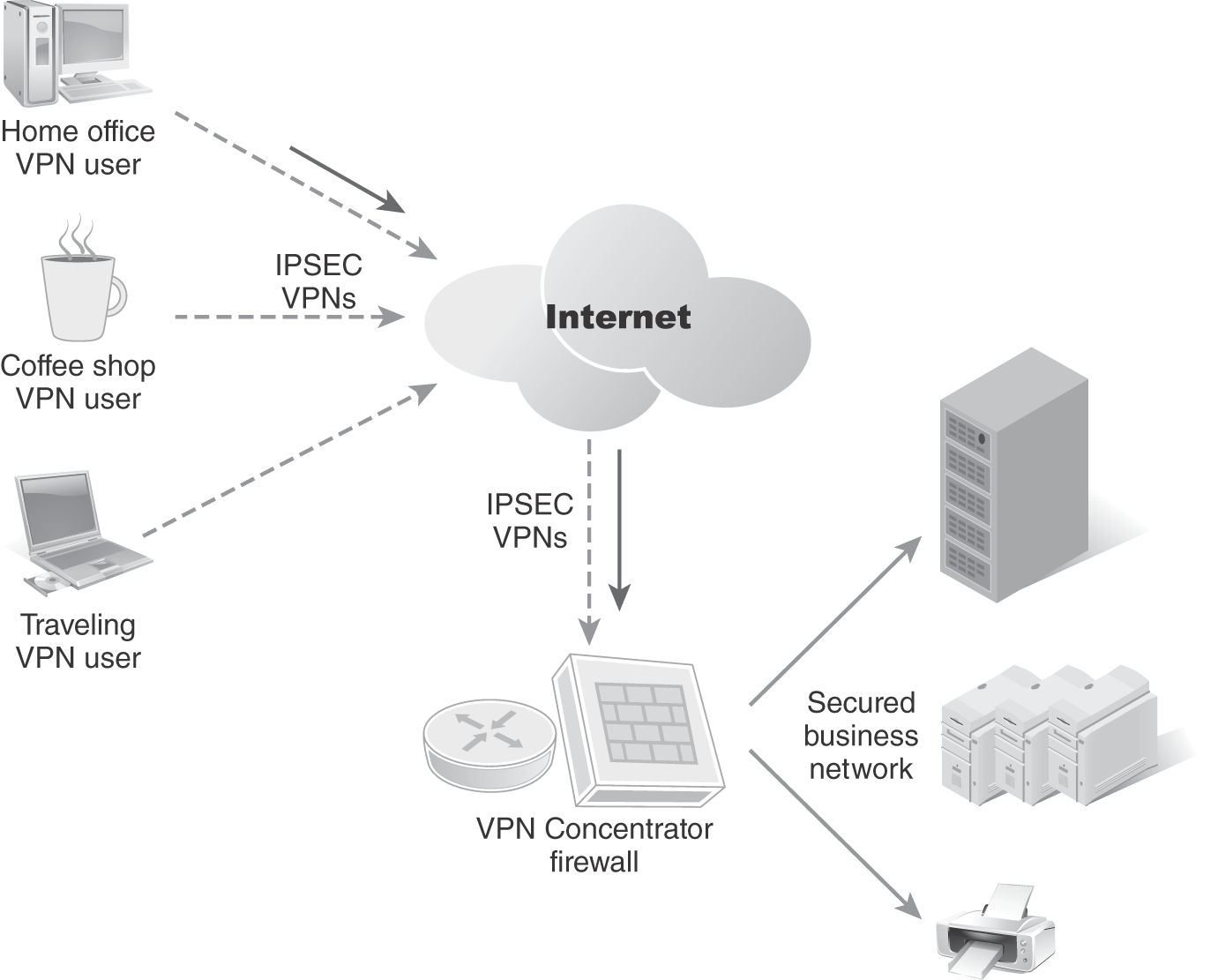
FIGURE 9-14 VPN concentrator terminating remote VPN connections.
Performance-Enhancing Devices
There are many network devices and appliances that can provide a specific function or performance enhancement to the network. These devices include:
- Load balancer—A network traffic device that helps distribute network or application traffic to specific servers. A load balancer does this by acting as a traffic cop, directing IP packets accordingly. Load balancers are typically installed at Internet ingress points where remote users access the network.
- Proxy server—A proxy server is a computer with an IP address known to the client that acts as an intermediary between the client and a target server. No direct communication takes place between the client and the target server when using a proxy server.
- Wireless LAN controller—A device that aggregates APs into a cohesive WLAN infrastructure. Wireless LAN controllers help network administrators manage WLANs and APs, and monitor network traffic loads and bandwidth. Each wireless LAN controller can support multiple APs in a geographical zone.
FIGURE 9-15 shows remote users wanting to connect to a different application. Load balancers are positioned at the Internet ingress point to connect the users to specific servers and applications.
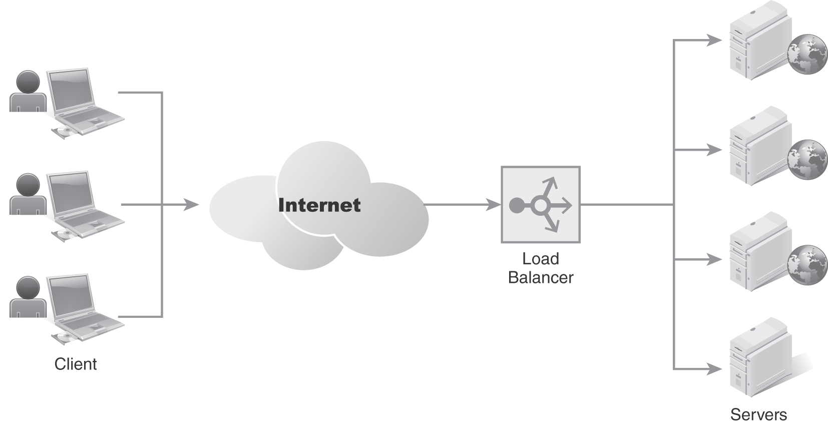
FIGURE 9-15 Load balancer distributes network traffic to servers.
Data from https://hackernoon.com/what-is-load-balancers-and-how-does-it-work-ep1jr3zcw.
Technical TIP
A proxy server typically resides in the public-facing DMZ/VLAN where remote users can access the proxy server. Inbound and internal users can access the proxy server when going outbound to the Internet. Proxy servers act as an intermediary between the client and a target server. No direct communication takes place between the client and the target server when using a proxy.
Think of a proxy server as a middleman in any inbound or outbound communication to the public Internet. It is enabled for security reasons and prevents users from directly accessing rogue or insecure websites. FIGURE 9-16 depicts a proxy server acting as a middleman for public Internet access for an internal workstation.
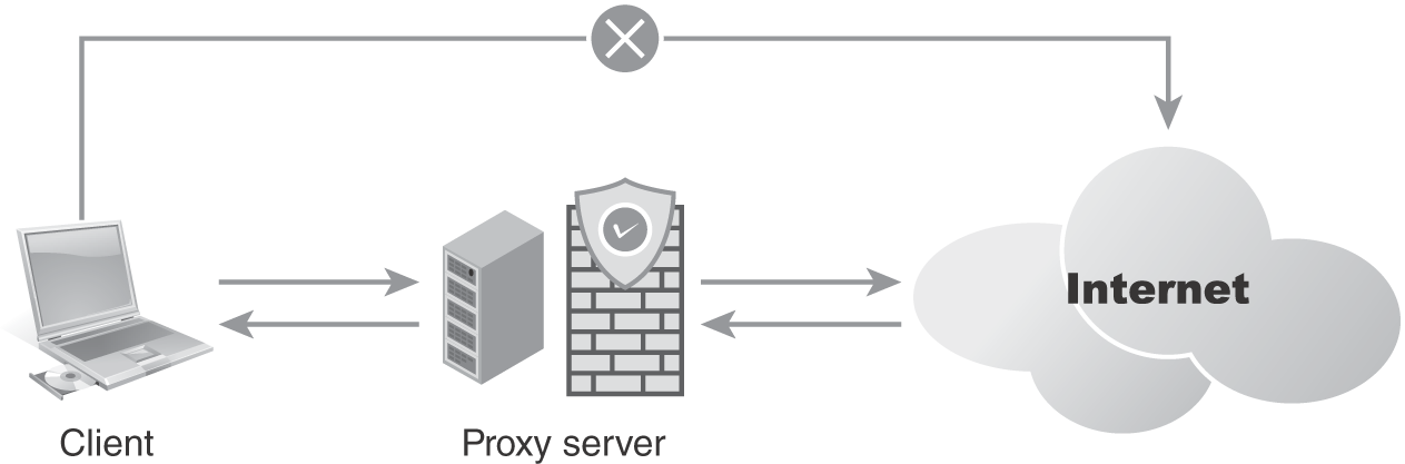
FIGURE 9-16 Proxy server acting as the middleman for inbound/outbound Internet traffic.