How Multiple Nodes Share Network Media
How does Ethernet work? How do PCs and workstations send and receive traffic to and from servers? What happens when there are too many workstations trying to communicate? What happens when workstations communicate simultaneously? How did Ethernet evolve to combat these bus topology problems?
Ethernet solved the problem of how to connect multiple PCs and workstations. Along with it came the most popular method of accessing shared media. This access control is what’s referred to as carrier sense multiple access with collision detection (CSMA/CD); it defines a set of rules for when a PC or workstation can transmit and how to handle collisions. Behind CSMA/CD is a simple concept that only one device can transmit data at a given time or else a collision will occur. The CSMA/CD rules formalize how humans have talked with one another for thousands of years.
Let’s break down CSMA/CD into the following pieces:
- Carrier sense—NIC cards listen on the physical media for specific voltage levels or carrier signals. If the coast is clear, the NIC can transmit on the network. If someone is already transmitting, you will know because the carrier sense voltage level is different.
- Multiple access—NIC cards can transmit simultaneously. When this occurs, it causes a collision situation on the physical media. This collision is noticed by the NIC card transceivers that listen to specific voltage levels or carrier signals.
- Collision detection—NIC cards react to signal collisions by retransmitting after receiving notification that a collision occurred. Although this solution solves the problem caused by the initial collision, bus topologies with excessive collisions also can cause problems.
Ethernet uses a nondeterministic, unpredictable transmission approach. Ethernet doesn’t try to prevent all collisions; it merely listens and transmits. This potential for collisions is what makes Ethernet nondeterministic. Because all of the nodes on an Ethernet network share the same transmission media, there must be some way to handle collisions. Avoiding collisions and incorporating collision detection is the goal of CSMA/CD. Before any node can transmit, it first listens to the media for any current traffic. If the media is available to transmit, it has a specific voltage level that tells transceivers the coast is clear. If the media is not available to transmit, a carrier signal is detected by the transceiver, indicating that a transmission is occurring. If the transceiver doesn’t detect any current traffic, the node starts to transmit. FIGURE 4-15 shows how carrier sense multiple access works.
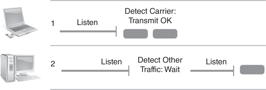
FIGURE 4-15 Ethernet carrier sense multiple access.
As the NIC transmits onto the media, it continues listening to the medium. If the transmission is valid, the destination node receives the entire Ethernet frame for processing. An invalid Ethernet frame indicates that two frames have collided. When this happens, the transceiver of the transmitting node stops transmitting. The node then waits for a random amount of time, referred to as the backoff algorithm, and then retransmits when the carrier sense condition is obtained. The random wait time reduces the possibility that the same nodes will transmit colliding frames again simultaneously. FIGURE 4-16 shows how Ethernet collision detection works.
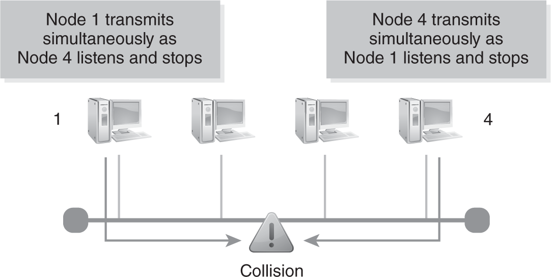
FIGURE 4-16 Ethernet collision detection.
People-to-People Communications
People have used CSMA/CD for over 45 years, but it’s based on basic human rules of communication. Nearly all of it is second nature—we rarely have to think about it. In fact, we generally don’t pay attention to the rules at all until someone fails to play by them. In conversation, it all comes down to three basic rules:
- Listen to others so you can hear if anyone else is talking.
- Don’t talk when someone else is already talking.
- If you do interrupt someone else, stop talking and wait until they are done.
The telephone network provides a good example of how people use CSMA/CD to communicate. Many rural areas didn’t immediately receive direct telephone service to every home. In low population areas, it was common to connect several houses to a shared telephone line. This was called a party line. Anyone who wanted to place a call would pick up the handset and listen for a dial tone. A dial tone meant no one else was currently on the line. If other people were talking, you could join in the conversation as long as you didn’t talk over other people. It was good manners to treat a party line like a face-to-face conversation. As more people joined a conversation, it became harder to coordinate who could talk. Think about the last time someone interrupted you or talked over you. It probably interfered with your ability to communicate. The same problem occurs in network communications.
CSMA/CD and the deployment of Ethernet LAN technologies evolved rapidly (FIGURE 4-17). From 10 Mbps baseband coaxial LAN topologies, to GigE to the desktop, to metro-Ethernet MAN connectivity, Ethernet has become the de facto standard for transporting Internet Protocol (IP)-based communications to the desktop. Ethernet made a huge impact on how IP-based communications and networking is delivered end-to-end to PCs and workstations. CSMA/CD has proven to be more scalable than other LAN technologies. This was driven by the fact that Ethernet technology and chipsets were able to increase Ethernet bandwidth speeds 10 times from 10 Mbps to 100 Mbps to 1000 Mbps to 10 Gbps speeds. Today, Ethernet supports up to 400 Gbps trunk bandwidth speeds on single-mode optical fiber. With Layer 2 and Layer 3 LAN switches providing each port an Ethernet LAN segment or collision domain, collisions are avoided. This provides PCs, workstations, and servers with their own dedicated switched Ethernet LAN connection. This maximizes throughput and performance for all devices. With structured wiring systems providing high-grade unshielded twisted-pair cabling to the desktop, users can now migrate their LAN connections from 10Base-T to 100Base-T to 1000Base-T or 10 Gigabit Ethernet to the desktop. LAN switches make it possible for many devices to be LAN-attached via Ethernet. Ethernet has proven to be highly scalable at an affordable price throughout its history. FIGURE 4-17 depicts the bandwidth evolution of Ethernet technology.

FIGURE 4-17 Ethernet technology bandwidth speed evolution.