Network Layer Basics
The Network Layer (Layer 3) of the OSI Reference Model defines the functions and activities that are to occur between the Transport Layer (Layer 4) and the Data Link Layer (Layer 2) to facilitate and ensure the transfer of data from its source to its destination. Included in the functions and actions defined on the Network Layer are:
- Datagram/packet encapsulation—Layer 3 functions include encapsulating messages passed from higher layers into datagrams (also called packets) along with Network Layer header information. The Layer 3 datagram is encapsulated within the Ethernet II frame format at the Data Link layer.
- Error handling and diagnostics—Layer 3 defines special-purpose protocols that allow logically connected devices to exchange information about the status of a network host or themselves.
- Fragmentation and reassembly—Layer 3 passes datagrams to the Data Link Layer, which has limits on the length of some of its frames for transmission. To facilitate the exchange between Layer 3 and Layer 2, the Network Layer breaks up a datagram (packet) into fragments that must fit within the maximum transmission unit (MTU) size of the Data Link Layer frame format. Data or messages coming from Layer 2 to be eventually passed on to the Transport Layer must be reassembled first. (See the sidebar entitled “IP Fragmentation” for an example of how this works).
- Internetwork routing—The primary function of the Network Layer is to move data across a series of interconnected networks. Therefore, the purpose of the devices and software on the Network Layer is to examine each Network Layer packet and its Network Layer addresses from various sources, extract their final destination, and forward them to the route that is the best path toward that destination.
- Logical addressing—Every device on a network has a logical address, which also is called a Layer 3 or Network Layer address. Whereas the MAC address (Layer 2) is a device’s physical address, its corresponding IP address (Layer 3) is a logical address. The main difference between these two addresses is that a logical address is assigned independently to the device. Should the device leave a network, its logical address (IP address) can be assigned to a different network device. One similarity the two addresses share is that they both must be unique addresses on a given network.
IP Fragmentation
The Internet Protocol (IP) is the core Network Layer protocol. To send messages using IP, higher-layer data must be encapsulated into IP datagrams. Encapsulation means to wrap higher-layer data with additional information before passing it to a lower layer. These datagrams are then sent to the Data Link Layer, where they are further encapsulated into frames for the technology in use to carry them physically to their destinations. On the Network Layer, IP puts Transport Layer messages, including the headers and trailers of all higher layers, into the data field of an IP datagram. On the Data Link Layer, the entire IP datagram is encapsulated into the payload of the applicable frame format. FIGURE 8-1 shows how data is encapsulated at each layer.
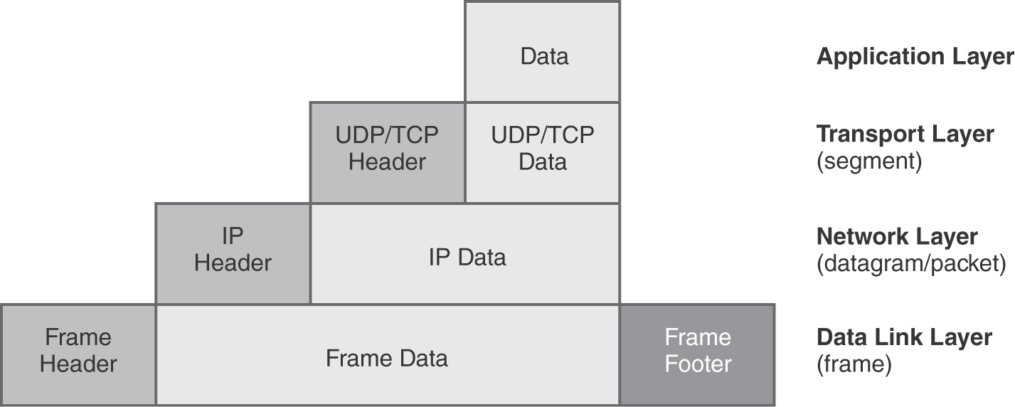
FIGURE 8-1 Data encapsulation.