IEEE 802.3ad Link Aggregation
VLANs provide the ability to segregate network traffic and increase performance. They make it possible to isolate certain types of traffic to their own collection of ports. The idea is to remove other types of traffic that can cause congestion and collisions. For example, an organization may choose to create a VLAN that transports only streaming video content. Creating a separate VLAN and using dynamic membership by protocol removes video traffic from other types of traffic. Sometimes, even the entire bandwidth of a single link is not enough. Link aggregation addresses this problem. Another important standard, IEEE 802.3ad, defines a standard method to combine multiple physical links so they can be used as a single logical link. This is also referred to as trunking. This process, shown in FIGURE 7-14, is called by various names, such as link aggregation (the standard definition) or link bundling, port trunking, NIC teaming, and others.
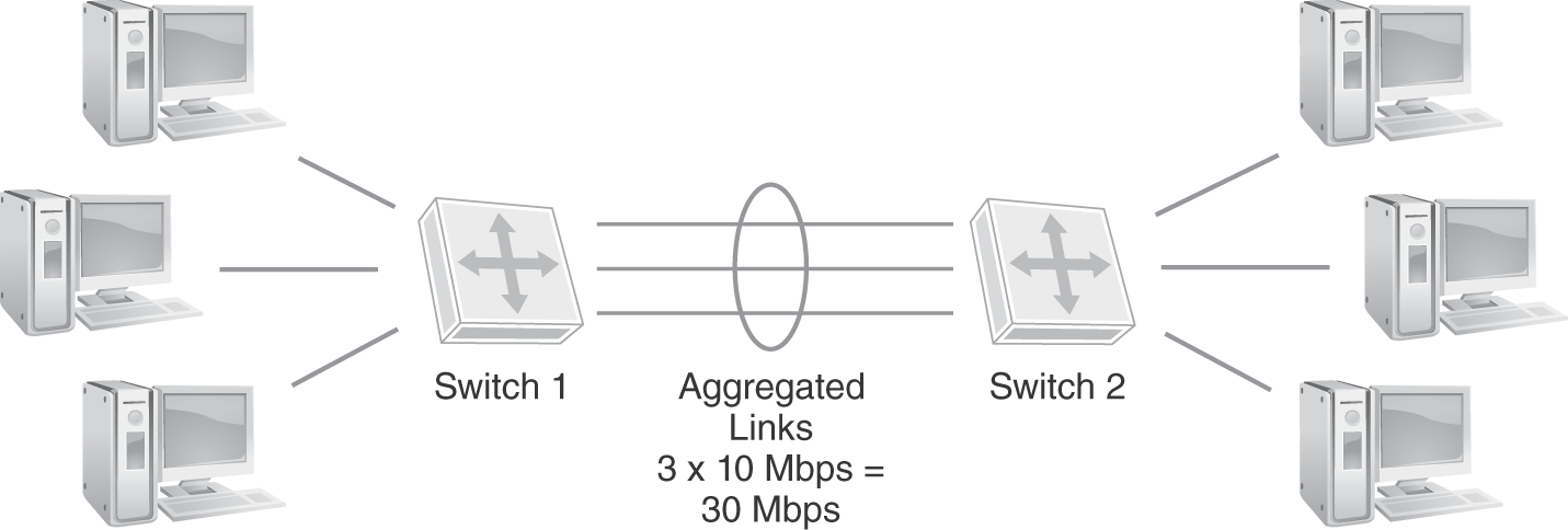
FIGURE 7-14 IEEE 802.3ad link aggregation.
 NOTE
NOTE
IEEE 802.3ad was originally introduced in 2000. It standardized work that many manufacturers had done to offer proprietary solutions. The standard was transferred to the 802.1 working group in 2008 to resolve discrepancies in protocol stack standard placement. Prior to its move, link aggregation defined a protocol stack standard that operated below 802.1 standards.
Technical TIP
Some manufacturers define the configuration variables for IEEE 802.3ad link aggregation operations differently. For instance, Cisco uses the term etherchannel for a port that’s defined to support link aggregation (both its proprietary version and 802.3ad). HP uses the term trunk in its original switch products and bridge aggregation in products acquired from 3Com. Consult the manufacturer’s documentation for clarification on 802.3ad link aggregation configuration.
Link aggregation allows switches to communicate along several physical links in parallel. FIGURE 7-14 illustrates that three 10 Mbps trunks provide an aggregate bandwidth of 30 Mbps. This has the effect of increasing the available bandwidth of a single link. For example, suppose a switch supports ports that use 1 Gbps links. The switch can use link aggregation to combine four links to provide a logical link with an effective bandwidth of 4 Gbps. Link aggregation also provides redundancy to protect from a single link failure. If any link in a bundle fails, the other links can still transport traffic. There are two main methods to configure link aggregation: static and dynamic bundling. TABLE 7-4 lists the advantages and disadvantages to each approach.
| METHOD | ADVANTAGES | DISADVANTAGES |
|---|---|---|
| Static aggregation |
|
|
| Dynamic aggregation |
|
|
Data from Department of Homeland Security.
The protocol that defines how dynamic link aggregation operates is called Link Aggregation Control Protocol (LACP). LACP provides the ability for compliant devices to negotiate link aggregation. This allows ports on both sides of a redundant link to configure into an aggregate link without the need for manual configuration. A switch sends LACP frames, called LACPDUs (where the DU stands for data units), out to all ports on which LACP is enabled. If the switch is connected to another device that has LACP enabled, the remote device responds with its own identification frames. The first switch examines the responses to detect duplicate links with another device. If the switch detects multiple links with another LACP-enabled device, it aggregates the active links automatically. LACP operates in one of two modes:
- Active—Send LACPDUs out to all LACP ports to detect other LACP devices.
- Passive—Don’t send LACPDUs but respond upon receiving LACPDUs.
Link aggregation provides inexpensive solutions to increasing bandwidth and resilience. Most high-end network devices support some kind of link aggregation. The technique is common when creating backbone networks. Backbone networks can benefit in measurable ways from increased bandwidth. They also rely on resilience to keep the network running. Link aggregation can help networks meet the needs of their users without large expenditures. Many network administrators acquire the fastest hardware their budget can afford and then explore boosting techniques such as link aggregation to make it even faster.
Technical TIP
Layer 2 networks support traffic shaping, which is the ability to divert network traffic down a specific network path or connection. Use of access control lists (ACLs) can be configured on Layer 2 switch ports to forward or filter MAC addresses, protocol type fields, or DSAP/SSAP fields in a Layer 2 Ethernet II frame or IEEE 802.3 CSMA/CD frame. ACLs are used to forward or block network traffic depending on MAC address or protocol.
Network Backbones
Structured wiring systems and rack-mounted hardware in data centers make moving nodes easier. The process of moving a node from one switch to another is a simple matter of moving a cable. The ease of central administration makes topologies that use central devices attractive. Such a topology is called a network backbone. You already have seen several backbone configurations. These networks take advantage of Layer 2 switching to separate collision domains and Layer 3 routing to separate broadcast domains. There are three basic types of backbones:
- Hierarchical
- Flat
- Collapsed
A hierarchical backbone is a topology that depends on Layer 3 routers to separate LANs from one another. Routers are connected to a common medium, such as a bus. This topology is possible with centralized or distributed switches and routers. As long as the bus reaches all of the routers, the hardware doesn’t have to be concentrated in a data center. The main problem with hierarchical backbones is that they rely on Layer 3 routing to communicate between LANs. A message must travel through two routers and the shared medium to reach a destination. FIGURE 7-15 shows a hierarchical backbone topology.

FIGURE 7-15 Layer 2 hierarchical backbone.
The flat backbone topology was developed to address the performance problems with the hierarchical backbone topology. Instead of relying on Layer 3 routers to connect LAN segments to the shared medium, the flat backbone uses Layer 2 switches. Using a Layer 2 device makes getting frames to their destinations faster than Layer 3 routing. A side effect of using a flat backbone is that the entire LAN becomes a single broadcast domain. Like the hierarchical backbones, the flat backbone allows switches to be centralized or distributed. FIGURE 7-16 shows a flat backbone topology.

FIGURE 7-16 Flat Layer 2 network backbone.
The collapsed backbone was developed to further increase network performance. This topology relies on switching hardware located in a central location.
The advantage of centralized switching is that there is no longer a need for a shared bus. The shared bus could become a source of collisions. The collapsed backbone topology makes each message transfer between segments a point-to-point connection. That speeds up each exchange and reduces overall collisions. A completely collapsed backbone also has fewer devices to manage because all segment connections go through a single switch.
Collapsed backbones do have a few drawbacks. First, the centralized nature of the topology requires that every device connect to the central switch. There must be a direct line either between each device or to intermediate devices between the central switch and endpoints. This requirement can cause longer cable runs and potentially result in signal loss. Another drawback is the reliance on a central switch. A single switch for the entire network means that if the switch fails, the whole network fails. Nodes can still communicate within each segment but not with nodes on other segments. FIGURE 7-17 shows a Layer 2 collapsed backbone.

FIGURE 7-17 Layer 2 collapsed backbone.
Today’s data centers commonly use a variation of the completely collapsed backbone. A popular alternative is a fiber optic collapsed backbone. With a collapsed backbone, the actual backbone is the backplane of the network switch. A rack-mounted collapsed backbone is a combination of a collapsed backbone and a flat backbone. It includes rack-mounted switches that are also connected to a high-speed routing switch. Many rack-mounted switches provide the ability to connect with other switches using extremely high-speed connections, such as fiber optic or on-board bus.
FIGURE 7-18 shows a fiber optic data center collapsed backbone.

FIGURE 7-18 Data center collapsed backbone.
The combination of centralizing hardware and using high-speed interconnections can provide the performance required by today’s media-centric applications. When using rack-mounted switches, backbone speeds of up to 100, 200, or 400 GigE are possible. Current vendors also are providing more options to support redundant hardware to make it possible to continue operations during a hardware failure and recovery.
Network Power
As organizations began to implement networked devices, they began to need more power. Endpoints and network devices all need power to operate. Early Ethernet networks depended exclusively on external power supplies. IEEE 802.3af–2003, and the later updated standard, IEEE 802.3at–2009, describe the technique for providing electrical power with the Ethernet data. The technology is called Power over Ethernet (PoE). The ability to deliver data and power in the same cable means that PoE-capable devices can operate anywhere an Ethernet connection is available. PoE provides transportability and flexibility for today’s network devices.
PoE in the Enterprise
Many current deployments of enterprise networks will include some form of PoE. The original IEEE 802.3af–2003 standard allowed for a maximum distribution of 15.4 watts of DC power per port. As VoIP endpoint telephony devices became more advanced, and additional features were built in, the requirement came for additional power. The next IEEE standard, 802.3at–2009, also known as PoE+ or PoE plus, was developed to provide up to 25.5 watts of DC power. A standard known as 802.3az–2010, or Energy Efficient Ethernet, came about because of the need to save power. This standard achieves it by lowering the amount of power distributed when the device is idle.
PoE is typically deployed on access switches to which endpoint devices terminate. These switches come in various configurations. Some switches might have only the first few ports on the switch designated for PoE. Other switches can utilize PoE on all of the available switch ports. Switches densely populated with PoE devices often consume significantly more power, which drives up utility costs.
Some devices that are typically powered via PoE ports include:
- VoIP phones
- Wireless access points
- Security cameras, such as network webcams
- Badge readers
- Wall clocks using Network Time Protocol (NTP)
- Lighting controls
- Intercom and paging systems
Topologies that use centralized architectures make it easy to provide reliable power to Ethernet devices using PoE. Collapsed backbones and rack-mounted backbones provide convenient centralized points to locate power supply units for the rest of the network. Locating these devices in the data center helps to ensure infrastructure support for fault tolerance. Some vendors, such as Cisco, provide hardware options to reduce overall power use by sharing excess power between multiple switches.
Large organizations that provide Ethernet connectivity to remote locations also can provide power for those devices. The ability of organizations to provide power for networked devices can be a huge benefit. They can ensure that networked devices such as switches, IP phones, and even thin client devices can operate through power failures or instability. For locations with unstable power, PoE can help to avoid operational interruptions.