
Towards Intersubband Polaritonics: How Fast Can Light and Electrons Mate?
NEST, CNR-INFM and Scuola Normale Superiore Piazza San Silvestro 12, 56127 Pisa, Italy
Fachbereich Physik and Center for Applied Photonics, Universität Konstanz Universitätsstrasse 10, 78464 Konstanz, Germany
Labo. Materieaux et Phénomènes Quantiques, Univ. Paris Diderot-Paris 7 and CNRS, UMR 7162, Bâtiment Condorcet, 75205 Paris, France
Laboratorio Nazionale TASC CNR-INFM, Area Science Park, 1-34012 Trieste, Italy
1. Introduction
Interaction of light with electronic excitations is a fundamental physical process that can be usually described in terms of absorption or emission of photons. The coupling between a single photonic mode and one elementary transition is quantified by the so-called vacuum Rabi frequency Ω. A strong-coupling regime is achieved when Ω is larger than radiative and nonradiative system loss rates: in this nonperturbative condition, eigenstates are linear superposition of photonic and electronic excitations. This peculiar regime is actively investigated in many research fields, such as ultracold atoms in optical cavities,1 Cooper-pair boxes in microwave resonators,2 excitonic transitions in semiconductor microcavities,3 and surface-plasmon resonators.4 In the case of atomic transitions, the coupling frequency is much smaller than the transition frequency ω12, which is the other relevant physical scale of the system. On the other hand, in condensed matter, while Ω can be dramatically larger, losses are more significant.5 Still, it was recently argued that an unprecedented ultrastrong coupling regime can be achieved when Ω becomes comparable with the transition frequency.6 Anomalous energy dispersion and a new class of quantum electrodynamics effects were predicted.7,8 We have investigated quantum-well intersubband excitations in semiconductor microcavities, demonstrating a value of Ω0 = 0.11ω12. A peculiar dispersion of the cavity polariton branches was consequently observed,9 proving that the anti-resonant light-matter coupling and the photon-energy renormalization become directly observable for the vacuum field, in excellent agreement with theory.6 Furthermore, we have exploited interband ultrafast pumping to optically tune light-matter interaction from weak to ultrastrong and turn on maximum coupling within less than one cycle of light.10 In this regime, a novel class of extremely nonadiabatic phenomena become observable. In particular, we directly monitor how a coherent photon population converts to cavity polaritons during abrupt switching. This system forms a new and promising laboratory for unprecedented sub-cycle QED effects and represents an efficient room-temperature switching device at the ultimate speed.
*Present address: Fachbereich Physik and Center for Applied Photonics, Universität Konstanz, Universitätsstrasse 10, 78464 Konstanz, Germany.
†Also with Labo. Pierre Aigrain, Ecole Normale Supérieure and CNRS, UMR 8551, 75005 Paris, France.
2. Intersubband cavity polaritons
Intersubband optical phenomena involve levels originating in a semiconductor heterostructure from the quantum-mechanical confinement of charge carriers in one direction. In n-doped quantum wells, intersubband absorption typically occurs in the range from mid-infrared to terahertz (THz) and can be observed with photons of transverse-magnetic (TM) polarization. Energy, carrier density, and matrix elements are the relevant parameters of the resonance, and can be tailored through structural design. Intersubband transitions offer a close similarity to atomic ones, as a consequence of their ideally delta-like joint density of states and of the large separation from continuum levels. The strong coupling with the electromagnetic mode of a planar semiconductor resonator, and the corresponding formation of the so-called intersubband polaritons, was observed in GaAs/AlGaAs5,11,12 and InAs/AlSb13 material systems, up to room temperature. In an intersubband microcavity of length Lcav, embedding NQW quantum wells doped to a carrier density of N2DEG, the coupling frequency can be expressed in Gaussian units as:
where d12 is the dipole moment of the transition, εr is the cavity dielectric constant and kz is the quantized cavity photon wavevector along the growth direction. At resonance, i.e. when the transition frequency ω12 is equal to the frequency of the cavity mode ωcav(k), the magnitude of the intersubband-polariton splitting 2![]() Ω0 = 2
Ω0 = 2![]() ΩR,kres can be maximized by the independent tailoring of these parameters and can become a substantial fraction of the transition energy, thanks also to the low energy and large dipole moment of intersubband excitations. These solid-state systems can be grown by mature epitaxial growth techniques such as molecular beam epitaxy (MBE) and represent optimal candidates to realize the ultrastrong coupling regime of light-matter interaction.
ΩR,kres can be maximized by the independent tailoring of these parameters and can become a substantial fraction of the transition energy, thanks also to the low energy and large dipole moment of intersubband excitations. These solid-state systems can be grown by mature epitaxial growth techniques such as molecular beam epitaxy (MBE) and represent optimal candidates to realize the ultrastrong coupling regime of light-matter interaction.
The Hamiltonian of the intersubband microcavity can be written using a bosonic approximation, since the excitation density of the transition (intersubband excitations per unit area of the sample) is very small compared to the density of the two-dimensional electron gas.6 The Hopfield-like Hamiltonian then takes the form:
It consists of three qualitatively different contributions that we shall analyze separately. The first term Hres is given by:
where ak† (ak) is the creation (annihilation) operator for the fundamental cavity-photon mode with in-plane wavevector k and frequency ωcav, and bk† (bk) is the creation (annihilation) operator of the bright intersubband-excitation mode of the doped multiple quantum well structure. Hres describes the energy of the bare cavity photon, the intersubband polarization field, and the resonant part of the light-matter interaction (corresponding to the creation/annihilation of one photon with the concomitant annihilation/creation of an intersubband excitation with the same in-plane wavevector).
The middle term in (2) contains the diamagnetic term (proportional to the square of the vector potential A) and gives a renormalization of the photon energy due to the interaction with matter:
where, for a quantum well, the diamagnetic coupling constant Dk is approximately given by Dk ≈ ΩR,k2/ω12.6
The last term in (2) is comprised of the so-called “anti-resonant” terms, corresponding to the simultaneous creation and annihilation of two excitations with opposite in-plane wavevectors:
Matrix elements of (5) are non-zero only when coupling states with different total number of cavity photons and intersubband excitations. This term is suppressed in first order perturbation theory. Neglecting Hanti-res, the Hamiltonian (2) commutes with the boson number and can be block-diagonalized in a finite dimensional subspace. This kind of approximation is the keystone of all analytical results in the field of light-matter interaction, and is usually known as rotating wave approximation (RWA).14 Experimental evidence of its violation was found only for the case of dressed states in strongly-driven systems with a large number of photons, by observing energy shifts or forbidden transitions.14,15
3. Ultrastrong coupling regime
The elusive Hdia and Hanti-res contributions to the interaction with the vacuum field are the hallmark of the ultrastrong-coupling regime and at the origin of the peculiar quantum nature of the states.6 A simple spectroscopic identification, for instance based on the excitation energies, would be extremely challenging in most microcavity systems. In reality, though, the situation of intersubband microcavities, which use a planar geometry with a resonator designed to operate at oblique incidence, is quite special. Measurements at large angles, in fact, highlight energy deviations of the polariton dispersion, as exemplified in Fig. 1. This effect originates from the fact that different polariton energies calculated for the same k would be observed at different angles in a linear optical experiment.16
Polariton energies measured at a fixed angle are those obtained from the intercepts of the ω(k) polariton curves with the line ω= ck/nsinθ). For the large experimental angles used, this has a similar slope to a good portion of the polariton dispersion. Small energy deviations between two polariton curves (for instance those calculated with and without the anti-resonant term) produce then larger energy differences in the intercepts, i.e. in the peak positions at that given angle.
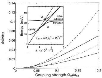
Figure 1. Difference from the full-Hamiltonian eigenvalues of the polariton energies calculated either without the Hanti-res term (lower curves) or without both Hanti-res and Hdia (upper curves) plotted as a function of coupling strength (solid and dashed lines refer to the lower and upper polariton branch, respectively). This calculation was performed for a fixed resonant angle of 60°. Clearly, deviations amount to ~5 % already for ΩR/ω12 ~ 0.1. The Inset shows schematically the dispersion of the two polariton branches; the intercepts with the light line at the specific angle correspond to the minima measured in a reflectance experiment.
Optical confinement in the microcavity used in this investigation is based on total internal reflection from a low refractive-index cladding at the bottom and on reflection from a semiconductor-metal interface at the top, see Fig. 2.17 The hetero-structure was grown by solid-source MBE on an undoped GaAs (001) substrate. The cladding region was realized by sandwiching a 1.65 μm AlAs layer between two GaAs layers doped to 5×l018 cm”3, each having a thickness of 150 nm. Thickness and doping level of the cladding layers were carefully tuned to ensure a strong optical confinement in the cavity, but at the same time enough coupling with the outside to allow for a clear identification of the polariton features. The active region consists of 70 repeats of n-doped 6.5 nm thick GaAs quantum wells separated by 8 nm thick Al0.35Ga0.65As barriers. Layer thicknesses were chosen so as to have only two bound subbands and ensure quantum decoupling of adjacent wells. The doping level (3.25×l012 cm–2 in each well) leads to population of the ground state only and to a single intersubband transition.
Light was coupled into the microcavity through the substrate, and the cavity throughput was probed by angle-resolved reflectance measurements. The experimental geometry is detailed in Fig. 2: the sample was mechanically lapped into a wedge-shaped prism with the polished facets at an angle of 70° with respect to the cavity plane. The prism was soldered onto a copper block and mounted inside the sample compartment of a Nicolet Fourier-transform infrared spectrometer (FTIR), equipped with an Ever-Glo source and a liquid-nitrogen cooled HgCdTe detector. A metallic wire-grid polarizer was inserted in the optical path to select the TM polarization of the probe beam. By manually rotating the sample holder, the angle between the infrared beam and the prism facet could be varied, enabling us to change the incident angle (θint) on the cavity surface around the central value of 70° defined by the prism shape.

Figure 2. Schematic diagram of the experimental set-up employed for the angle-resolved reflectance measurements. The prism-shaped sample is mounted on a copper block and can be rotated to vary the internal incidence angle. The blown up detail of the waveguide illustrates the working principle of the resonator: large arrows show the optical path of the light in the substrate, dotted white arrows denote evanescent-wave coupling in and out of the resonator, and solid white arrows correspond to intracavity reflections. The cavity core consists of 70 repeats of GaAs/AI0.35Ga0.65AS quantum-well units. The band profile and squared moduli of the subband envelope functions of one of the quantum wells are shown in the top left inset.
Figure 3(a) shows the angle-resolved TM reflectance spectra in the frequency range of the intersubband transition. The spectra were collected at room temperature, with a resolution of 0.25 meV. Curves display two dips corresponding to the formation of intersubband polaritons. The minimum splitting between the polariton dips is about 90 meV, although a precise anti-crossing point cannot be defined: the two structures shift almost in parallel to higher energies with increasing θint. This behavior stems again from the fact that polariton peaks at the same internal angle do not correspond to the same k.16 The bare intersubband-transition energy of the active region was measured in another wedge-shaped prism, polished at a 45° angle. The reflectance spectrum was collected at an internal angle of about 37°, which excluded any cavity-induced shift of the intersubband absorption. The recorded transition energy is 152 meV, with a full width at half maximum (FWHM) of about 12 meV.

Figure 3. (a) TM reflectance spectra of the microcavity sample wedged at 70° for different internal angles of incidence θint at the substrate-cavity interface (values given in degrees). Data were collected at 300 K with a resolution of 0.25 meV. Spectra are offset for clarity. (b) Angle-resolved reflectance of the intersubband microcavity displayed as a contour plot in logarithmic scale. The superimposed curves are theoretical calculations with 2![]() Ω0 = 17 meV, computed using the full Hamiltonian (circles), without the anti-resonant term only (squares), and without both photon energy renormalization and the anti-resonant term (triangles). The right panel shows the reflectance spectrum corresponding to the internal angle of 68.5°. Arrows show the calculated lower-polariton energies for the three Hamiltonians detailed above.
Ω0 = 17 meV, computed using the full Hamiltonian (circles), without the anti-resonant term only (squares), and without both photon energy renormalization and the anti-resonant term (triangles). The right panel shows the reflectance spectrum corresponding to the internal angle of 68.5°. Arrows show the calculated lower-polariton energies for the three Hamiltonians detailed above.
Since the bottom mirror utilizes total internal reflection, one cannot determine precisely the cavity resonance energy through measurements at zero incidence, where the intersubband transition does not couple to the radiation. In order to avoid unnecessary fitting parameters or relying on the uncertain knowledge of dielectric constants and growth rates, we decided to use a second sample, identical in the growth sequence, but without any doping in the active region. Angle-resolved reflectance measurements conducted in this latter sample were then used to determine the energy dispersion of the cavity mode. The quality of the growth and the thickness difference between the two samples were checked using X-ray diffraction (XRD). The reference sample was also wedged at an angle of 70°; Scanning electron microscope (SEM) images of the cleaved facets of the two wedge-shaped samples were recorded to check the angular difference between the mechanically polished facets. Having measured both the intersubband transition energy and the angle-dependent cavity mode frequency, we proceeded to model the data, with the vacuum Rabi frequency as the only free fitting parameter. In order to prove that our intersubband microcavity is indeed in the ultrastrong coupling regime, we compare in Fig. 3(b) the measured reflectance with the computed polariton dispersion curves. The energies calculated from the full Hamiltonian (2) are shown as white circles. A perfect agreement is found for a vacuum Rabi energy hΩ0 = 17 meV, ~11 % of the intersubband transition energy.9 Note that, as discussed in Ref. 16, the actual value of the vacuum Rabi energy is much smaller than half the splitting observed in the spectra. The triangles in Fig. 3(b) were instead obtained neglecting both Hdia and Hanti-res terms, while the squares exclude only the anti-resonant contribution but include the photon renormalization. Though only small deviations appear for the upper polariton, the lower polariton dispersion calculated with either of the latter approximations is clearly incompatible with the experimental measurements. In order to better quantify this difference, the 68.5° spectrum is analyzed in detail in the right panel of Fig. 3(b). The energy derived without Hanti-res is 6 meV above the measured polariton dip, while that without Hdia and Hanti-res is 13 meV below, both well beyond the experimental resolution.
4. Nonadiabatic switching
In the ultrastrong coupling regime, the anti-resonant terms of the interaction become relevant already in equilibrium; as a consequence, the ground state of the system is a squeezed vacuum containing a finite number of virtual photons.6 As long as the vacuum is confined inside the cavity, its quantum nature may be regarded as an academic question. Theory, however, shows that nonadiabatic switching of ΩR may release these virtual quanta in correlated pairs.6,8 As a matter of fact, nonadiabatic control poses an extreme experimental challenge: changes are required to be induced on a scale set by the cycle of light. Electronic tuning via an external gate voltage17,18 is clearly too slow; theoretical proposals to modulate the dielectric constant of a cavity or the reflectivity of a mirror have not been implemented for the required time scale either.
To overcome this challenge, we implemented an all-optical scheme for femtosecond control of ultrastrongly coupled cavity polaritons – a first practical test-bed to target nonadiabatic QED phenomena.10 The concept is illustrated in Fig. 4. For maximum modulation, we start with an empty microcavity and turn on light-matter coupling by direct injection of the emitter itself. Our sample contains 50 identical, undoped GaAs QWs separated by Al0.33Ga0.67As barriers. Radiative transitions between the subbands only become possible if electrons are injected extrinsically. The intersubband absorption line is centered at hω12 = 113 meV (wavelength λ = 11 μm). The effective thickness of the structure corresponds to λ/2 at an internal propagation angle of θ = 65°. We employ a 12-fs control pulse centered at a photon energy of 1.55 eV19 to excite electrons resonantly from the valence band into conduction subband |1> (vertical beam in Fig. 4 and thick arrow in the inset), activating the intersubband field within femtoseconds.

Figure 4. Femtosecond switch of ultrastrong light-matter coupling. A bare microcavity features minimal reflectance R(ω) at the photon resonance ωC. After introduction of a degenerate quantum emitter, vacuum fluctuations of the photon field are coherently absorbed and reemitted at a rate ΩR, giving rise to anticrossing cavity polaritons. The 50 undoped GaAs quantum wells are embedded into a planar waveguide structure based on total internal reflection on either side. The QWs are positioned at the field antinode. Electronic transitions between subbands |1> and |2> are activated by near infrared 12-fs control pulses (vertical beam) populating level |1>. Intersubband transitions may then resonantly couple to TM polarized mid-infrared cavity photons propagating at θ = 65°. Few-cycle multi-THz transients guided through the prism-shaped substrate are reflected off the waveguide to probe the ultrafast buildup of the mixed light-matter system. The pulse front of the near-infrared control is tilted (broken circle in control beam) to match the geometry of the phase planes of the probe.

Figure 5. (a) THz reflectance spectra measured at room temperature for various fluences Φ (vertically offset) of the control pulse (tD = 20 ps). Minima indicate eigenmodes of the system. (b) Spectra of the reflected THz field are given for various delay times tD (offset vertically). The 12-fs control pulse (Φ0 = 0.1 mJ/cm2) arrives at tD = 0. Central arrow: bare cavity resonance, lateral arrows: ultrastrongly coupled intersubband cavity polariton branches.
The eigenmodes of this system are probed by resonant scattering of a second light pulse: a TM polarized phase-locked mid-infrared transient (oscillating curve in Fig. 4) is coupled through the prism-shaped substrate and reflected off the photoexcited area of the waveguide. In order to achieve sub-cycle temporal resolution, we map out the real-time oscillations of the field of the reflected pulse by phase-matched electro-optic detection.20 Eigenmodes of the cavity are identified via characteristic minima in the Fourier spectra of the reflected transients. All experiments are performed under ambient conditions.
Figure 5(a) demonstrates that ΩR is continuously tunable via the control fluence Φ: a series of spectra is recorded for a fixed delay time tD = 20 ps between the near-infrared control and the multi-THz probe pulse. In equilibrium (Φ = 0), a single reflectance minimum at hωC = 113 meV (top curve) attests to the only resonance of the unexcited cavity, the bare photon mode. With increasing fluence, the system traverses all three regimes of light-matter interaction: starting with a broadening of the cavity line in the weak coupling regime (Φ ≤ 0.03Φ0, where Φ0 = 0.1 mJ/cm2), ΩR exceeds the widths (FWHM ~ 5 meV) of intersubband and cavity resonances already for Φ > 0.07Φ0, and two strongly coupled cavity polariton branches become clearly discernible. Further increase of the fluence enhances the separation of the minima to 50 meV, corresponding to 44% of the bare photon frequency. This value is comparable to what has been achieved before in doped structures and fulfils the criteria of ultrastrong coupling. We expect the scheme to be further scalable by using a higher control fluence.
The central question however is: how rapidly may ultrastrong coupling be activated? Figure 5(b) displays amplitude spectra recorded at various delay times tD for Φ = Φ0. For tD ≤ –50 fs the cavity resonance (center arrow) is clearly seen with a minimum amplitude reflectivity below 10%. The control pulse induces dramatic spectral changes of order unity, on the femtosecond scale. The initial bare photon state is replaced by two coupled polariton branches appearing simultaneously at energy positions of 93 meV and 143 meV (side arrows in Fig. 5(b)). Most remarkably, the new resonances do not gradually develop out of the bare cavity mode. The system does not sequentially pass through all three regimes of light-matter coupling – a scenario that would manifest itself in a bifurcation similar to Fig. 5(a). Instead, switching from the bare resonance to ultrastrongly coupled polaritons occurs discontinuously. It appears that cavity-intersubband coupling forms quasi-instantaneously once level 11) is populated. Surprisingly, the bare photon mode suffers a distinct broadening already at negative delay times tD ≥ –100 fs. Moreover, in the neighborhood of tD = 0 fs, broadened versions of bare photon and polariton resonances seem to be present simultaneously.
These paradoxical features are fingerprints of a novel nonadiabatic phenomenon which we like to term “perturbed cavity emission decay”. The physics is most striking in the time domain, illustrated in Fig. 6.10 When a few-cycle multi-THz transient – the time trace in Fig. 6(a) – impinges on the unexcited modulator structure, part of its energy is directly reflected off the cavity surface. A second portion is transmitted into the structure, prepares a coherent photon state in the resonator, and gets reemitted subsequently, contributing to the overall reflected signal. This dynamics is encoded in a characteristic twin-pulse temporal structure of the reflected transient – see Fig. 6(b). The most intriguing situation is realized if we switch the eigenstates of the cavity while a coherent state of bare photons is still present, as in Fig. 6(c): the incident THz transient first prepares a photon population in the unexcited cavity. During the free emission decay (second burst of the reflected field), the control pulse abruptly alters the eigenstates of the system. Remarkably, the decay of the bare cavity mode is interrupted on a time scale shorter than the oscillation cycle of light – a compelling proof of nonadiabaticity. The subsequently reemitted transient exhibits a characteristic two-mode beating in the time domain. The corresponding spectrum displays minima at photon energies of 93 meV and 143 meV – the hallmarks of both polariton branches. The initial coherent photon population is thus effectively converted into ultrastrongly coupled cavity polaritons beating at the splitting frequency. The fact that both branches of the new eigenstates are populated simultaneously confirms that switching indeed proceeds nonadiabatically.

Figure 6. (a) Few-cycle transient incident on the microcavity structure; (b) time trace of the reflected THz field vs. time t (c) a 12-fs control pulse arrives within the coherence window of the cavity mode (vertical arrow). The reflected THz field traces the nonadiabatic switch-on of ultrastrong coupling: the control pulse abruptly changes the exponential emission decay into a characteristic beating signature.
5. Conclusions
The experiments described in this chapter open up a new domain of light-matter interaction at the ultrastrong and ultrafast limit. We have provided evidence that anti-resonant light-matter coupling and photon-energy renormalization can become significant even in the interaction with the vacuum electromagnetic field of a microcavity. Furthermore we have observed the nonadiabatic dynamics of a coherent photon population during sub-cycle switching. Such experiments provide a benchmark for latest cavity-QED theories in the ultrastrong coupling regime and encourage a systematic quest for nonadiabatic quantum optical phenomena.
References
1. Y. Colombe, T. Steinmetz, G. Dubois, F. Linke, D. Hunger, and J. Reichel, “Strong atom-field coupling for Bose-Einstein condensates in an optical cavity on a chip,” Nature 450, 272 (2007).
2. A. Wallraff, D. I. Schuster, A. Biais, et al., “Strong coupling of a single photon to a superconducting qubit using circuit quantum electrodynamics,” Nature 431, 162 (2004).
3. K. Hennessy, A. Badolato, M. Winger, et al., “Quantum nature of a strongly coupled single quantum dot–cavity system,” Nature 445, 896 (2007).
4. J. Bellessa, C. Bonnand, J. C. Plenet, and J. Mugneir, “Strong coupling between surface plasmons and excitons in an organic semiconductor,” Phys. Rev. Lett. 93, 036404 (2004).
5. D. Dini, R. Köhler, A. Tredicucci, G. Biasiol, and L. Sorba, “Microcavity polariton splitting of intersubband transitions,” Phys. Rev. Lett 90, 116401 (2003).
6. C Ciuti, G. Bastard, and I. Carusotto, “Quantum vacuum properties of the intersubband cavity polariton field,” Phys. Rev. B 72, 115303 (2005).
7. C. Ciuti and I. Carusotto, “Input-output theory of cavities in the ultrastrong coupling regime: The case of time-independent cavity parameters,” Phys. Rev. A 74, 033811(2006).
8. S. De Liberato, C. Ciuti, and I. Carusotto, “Quantum vacuum radiation spectra from a semiconductor microcavity with a time-modulated vacuum Rabi frequency,” Phys. Rev. Lett. 98, 103602 (2007).
9. A. Anappara, S. De Liberato, A. Tredicucci, et al., “Signatures of the ultrastrong light-matter coupling regime,” Phys. Rev. B 79, 201303 (2009).
10. G. Günter, Α. Α. Anappara, J. Hees, et al., “Sub-cycle switch-on of ultrastrong light-matter interaction,” Nature 458, 178 (2009).
11. E. Dupont, J. A. Gupta, and H. C. Liu, “Giant vacuum-field Rabi splitting of intersubband transitions in multiple quantum wells,” Phys. Rev. B 75, 205325 (2007).
12. L. Sapienza, A. Vasanelli, C Ciuti, C. Manquest, C. Sirtori, R. Colombelli, and U. Gennser, “Photovoltaic probe of cavity polaritons in a quantum cascade structure,” Appl. Phys. Lett. 90, 201101 (2007).
13. A. A. Anappara, D. Barate, A. Tredicucci, J. Devenson, R. Teissier, and A. Baranov, “Giant intersubband polariton splitting in InAs/AlSb microcavities,” Solid State Commun. 142, 311 (2007).
14. Ε. K. Irish, “Generalized rotating-wave approximation for arbitrarily large coupling,” Phys. Rev. Lett. 99 173601 (2007), and references therein.
15. S. Hofferberth, B. Fischer, T. Schumm, J. Schmiedmayer, and I. Lesanovsky, “Ultracold atoms in radio-frequency dressed potentials beyond the rotating-wave approximation,” Phys. Rev. A 76, 013401 (2007).
16. A. A. Anappara, A. Tredicucci, F. Beltram, et al., “Cavity polaritons from excited subband transitions,” Appl. Phys. Lett. 91, 231118 (2007).
17. A. A. Anappara, A. Tredicucci, G. Biasiol, and L. Sorba, “Electrical control of polariton coupling in intersubband microcavities,” Appl. Phys. Lett. 87, 051105(2005).
18. A. A. Anappara, A. Tredicucci, F. Beltram, G. Biasiol, and L. Sorba, “Tunnel-assisted manipulation of intersubband polaritons in asymmetric coupled quantum wells,” Appl. Phys. Lett. 89, 171109 (2006).
19. R. Huber, F. Adler, A. Leitenstorfer, M. Beutter, P. Baum, and E. Riedle, “12 fs pulses from a cw-pumped 200 nJ Ti:sapphire amplifier at a variable repetition rate of up to 4 MHz,” Opt. Lett. 28, 2118 (2003).
20. C Kübier, R. Huber, S. Tübel, and A. Leitenstorfer, “Ultrabroadband detection of multi-THz field transients with GaSe electro-optic sensors: Approaching the near infrared,” Appl. Phys. Lett. 85, 3360 (2004).